Advertisement
Quick Links
WARNINGS AND CAUTIONS
• TO AVOID SERIOUS PERSONAL INJURY, DO NOT RECHARGE, DISASSEMBLE OR INCINERATE BATTERY, NOR HEAT IT ABOVE 100° C (212° F).
Dispose of used battery promptly. DO NOT dispose of battery in normal household waste. Keep away from children. Please contact your local waste
provider or recycling facility for proper disposal of used battery.
• Replace battery with Panasonic, Energizer, Sony, Duracell, Rayovac or Maxell CR2450 only. Use of another battery may present a risk of fire or explosion.
• To be installed and/or used in accordance with appropriate electrical codes and regulations.
• If you are unsure about any part of these instructions, consult an electrician.
• For indoor applications only.
• Save these instructions.
COMPATIBLE DEVICES
• Lumina™ gateway (required for ZSC04 & ZSC15 operation)
• Lumina™ 10A Decora
Wall Switch
®
NOTES
• Requires Lumina™ gateway for programming and control communication to other devices.
• Do not mount the sensor until after it has been programmed to communicate with all
appropriate receivers.
LEVITON LUMINA™ RF WALL SWITCH OVERVIEW
The Lumina™ RF components are designed to communicate with each other via 2.4GHz
Radio Frequency (RF) to provide remote control of your lighting. Each module in the
Lumina™ RF component line is designed to act as part of a system. Line powered
devices are designed to act as a router. These routers will re-transmit the RF signal from
one device to another until the intended device is reached. This ensures that the signal
is received by its intended device by routing the signal around obstacles and radio dead
spots.
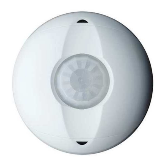
DESCRIPTION
The Occupancy Sensor is a 2.4GHz wireless communication device which transmits a
wireless message to the Lumina™ gateway. This communication occurs each time an
occupancy change occurs in a room, occupied to unoccupied or unoccupied to occupied.
The gateway then routes the message to the load control device to take assigned action.
Occupancy/Vacancy time delays are configured and maintained in the gateway and load
control devices; this improves the design and efficiency of the wireless system.
QUICK START: SETUP, PROGRAMMING AND ACTIVATION
NOTE: Remove "Battery Pull Tab" to activate device.
Make sure the sensor is within 16 feet (5 meters) of the desired receiver when
programming.
• Configure the Lumina™ RF occupancy sensor using a Lumina™ gateway with a PC
running the Lumina™ RF smart configuration software (see configuration videos and
software for detailed radio frequency pairing and control programming online at
www.leviton.com/luminarf). The device must be in Network Enrollment mode while
the Lumina™ gateway is searching for new devices to Enroll (see TABLE 2, MODE 1).
• Occupancy Sensor Programming: To associate a sensor with the receiving device
(gateway or other coordinator), remove the front access cover and use the MENU
button to enter the menu and enroll into a network (See TABLE 2, MODE 1 and the
Lumina™ gateway manual for details). Occupancy time delays are configured in
gateway or coordinator control device.
• Gateway Activation: Once the Occupancy Sensor has been associated with a gateway/
coordinator, that device can then specify which loads to turn ON or OFF each time the
sensor's field of view is entered (see configuration videos and software for detailed radio
frequency pairing and control programming online at www.leviton.com/luminarf).
OPERATION
LED Indicator (See TABLE 2, MODE 4)
The Lumina™ RF occupancy sensor comes equipped with an LED indicator that normally
flashes red for correct occupancy operation. This LED is also used during programming for
Menu and Mode selection.
• RED: PIR Motion detection (normal operation mode)
• AMBER: Signal to release push button when in Menu Mode
• GREEN: Represents a Menu mode or an active menu state (attempting to join a
network, identifying on the network, etc.)
OPERATION TESTING
1. Once joined into a network, confirm occupancy detection (RED LED will blink), then
cover the occupancy sensor so no further detection is detected.
a. Verify timeout and load turns OFF accurately
2. Uncover the occupancy sensor to verify Auto-ON responds and energizes load(s).
FIELD OF VIEW & SENSITIVITY TESTING
• Perform a FOV walk test of the coverage area and confirm the RED LED blinks and
detects within the responsible space (See TABLE 3).
• Adjust the sensitivity POT as necessary to increase or decrease the detection sensitivity
within the field of view.
PIR SENSITIVITY ADJUSTMENT: This can increase or decrease the amount of detection
points within the specified field of view. This does not increase or decrease the range of the
PIR detection.
INSTALLATION
Do not mount the sensor until after it has been programmed to communicate with all
appropriate receivers. Equipment needed for installation:
• Ceiling Tile Stem, Nut, & Washer (included)
• Double Sided Foam Mounting Tape (included)
• Screws (included) with Wall Anchors (not included)
Lumina™ RF Wireless Occupancy Sensor
Cat. Nos. ZSC04 & ZSC15
INSTALLATION AND QUICK START SHEET
Location: (Choose location to mount the sensor and the appropriate method -
Tile Stem, Screws, Mounting Tape)
1. Sensor location is very important to ensure correct operation within each unique space.
2. Improve performance to Auto-ON response and reduce risk of false tripping from
external motion (example: hallway traffic) by choosing the best location.
3. Do not locate a sensor on a mounting surface within 6 feet of - air ducts, moving
machinery, heat sources.
Sensor location
optimized for best
entry detection and
reduced nuisance
tripping from hallway
CEILING TILE MOUNT
1. Use the included ceiling tile stem, connect the stem to the back cover and twist to
secure, reference figures below for details.
2. In desired location, press the ceiling tile stem through the ceiling tile and install the
washer and nut above the ceiling tile to secure.
NOTE: The sensor back cover and front body are keyed with arrows for ease of
separation. To lock the sensor body to the back cover, align arrows and press
back cover to the front body, then rotate until the arrows are not aligned.
3. Rotate the sensor to the desired orientation.
Mounting Option Diagram A
Sensor Mounted to Drop Ceiling Using Tile Stem
Drop Ceiling
1" thick maximum
Tile Stem
SURFACE MOUNT USING SCREWS
1. To remove the back cover of the sensor, locate alignment arrow on the edge of the back
cover and on the edge of the front body, rotate the back cover and front body until the
two arrows line up and pull apart.
2. Install back cover of the ceiling sensor to desired location using the included screws
(nuts and washers), or screws in combination with commercially available wall anchors.
If necessary, drill pilot holes.
3. Secure the sensor body to the back cover by aligning the arrows. Lock it by turning the
sensor such that the arrows do not line up.
4. Rotate the sensor to the desired orientation.
Mounting Option Diagram B
Sensor Mounted to Wallboard or Drop Ceiling Using Screws
Nut
Washer
Wallboard
Ceiling
Sensor Back
Cover
Mounting
Screw
Sensor Base
Key lock
Sensor Front
Arrow
Cover
SURFACE MOUNT USING TAPE
1. Remove backing material and apply double sided mounting tape to the Sensor Base.
2. Press and hold the Wireless Occupancy Sensor to the desired mounting surface for a
few seconds before releasing. NOTE: The sensor back cover and front body are keyed
with arrows for ease of separation. To lock the sensor body to the back cover, align ar-
rows and press back cover to the front body, then rotate until the arrows are not aligned.
3. Rotate the sensor to the desired orientation.
DI-002-ZSCXX-00A
ENGLISH
Sensor location
center of room has
potential risk of
nuisance tripping
from hallway traffic
Nut
Washer
Back Cover (inside)
Mounting
Screw
Back Cover shown mounted
to ceiling with screws
Advertisement

Related Manuals for Leviton Lumina ZSC15


Summary of Contents for Leviton Lumina ZSC15
- Page 1 1" thick maximum www.leviton.com/luminarf). The device must be in Network Enrollment mode while the Lumina™ gateway is searching for new devices to Enroll (see TABLE 2, MODE 1). • Occupancy Sensor Programming: To associate a sensor with the receiving device...
- Page 2 During the warranty period, Leviton will restore corrupted operating systems to factory default at no charge, provided that the product has been used as originally intended. Installation of non-Leviton software or modification of the operating system voids this warranty. Leviton’s...
Need help?
Do you have a question about the Lumina ZSC15 and is the answer not in the manual?
Questions and answers