Table of Contents
Advertisement
Quick Links
Advertisement
Table of Contents

Related Manuals for Cardinal SB250 Series


Summary of Contents for Cardinal SB250 Series
- Page 1 SB250 Series Remote Display INSTALLATION MANUAL 3601-M481-O1 Rev C 203 E. Daugherty, Webb City, MO 64870 Printed in USA Ph: 417-673-4631 • Fax: 417-673-2153 07/10 www.cardinalscale.com Technical Support: Ph: 866-254-8261 • tech@cardet.com 3601-M418-O1 Rev C • SB250 Series...
- Page 2 3601-M418-O1 Rev C • SB250 Series...
-
Page 3: Table Of Contents
DATE OF PURCHASE _________________ PURCHASED FROM __________________ ____________________________________ ____________________________________ ____________________________________ RETAIN THIS INFORMATION FOR FUTURE USE PRECAUTIONS Before using this instrument, read this manual and pay special attention to all "WARNING" symbols: ELECTRICAL STATIC IMPORTANT WARNING SENSITVE 3601-M418-O1 Rev C • SB250 Series... - Page 4 For this reason the Seller is not able to guarantee the result of any procedure contained herein. Nor can they assume responsibility for any damage to property or injury to persons occasioned from the procedures. Persons engaging the procedures do so entirely at their own risk. 3601-M418-O1 Rev C • SB250 Series...
-
Page 5: Introduction
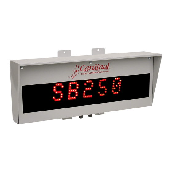
INTRODUCTION Thank you for your purchase of our Cardinal SB250 Series Remote Display. It was built with quality and reliability. This manual will guide you through installation, and operation of your display. Please read it thoroughly before attempting to install your display. Also, make certain that you pay attention to the warnings that appear in this manual. -
Page 6: Auto Learn Feature
Odd, Even or No parity Character format all standard ASCII characters One user protocol can be entered into the display using the serial port and Cardinal software. MULTIPLE DISPLAYS The SB250 display has been designed to be linked or daisy-chained to other SB250 displays allowing multiple lines of weight data to be displayed while being driven by a single serial port on the weight indicating instrument. -
Page 7: Installation
Attach the display to the wall and securely tighten the retaining bolts. Power Supply Auto-Learn AC Power Controller Terminal Block Figure No. 2 3601-M481-O1 Rev C • SB250 Series... -
Page 8: Ac Power Connection
AC power to the display. Figure No. 4 115VAC WIRING COLOR CODE TABLE Function U.S. Code International Code L1 (H) - Hot Black Brown L2 (N) - Neutral White Blue GND - Ground Green Green/Yellow 3601-M481-O1 Rev C • SB250 Series... -
Page 9: Auto Learn Controller Board
AUTO-LEARN CONTROLLER BOARD RS485 RS232 RS422 20mA Current Loop Figure No. 5 3601-M481-O1 Rev C • SB250 Series... -
Page 10: Status Led's And Display
S2 = (−) Used during programming to decrement to the previous parameter value. S3 = (MODE) Press to begin Setup and Configuration mode. During setup, press S3 to advance to the next setup parameter. 3601-M481-O1 Rev C • SB250 Series... -
Page 11: Serial Cable Installation
6. Insure that the termination jumper Figure No. 7 J6 is set correctly. It must be ON for termination or OFF for unterminated operation. 7. Install the Receive mode jumper J4, ON the 422 pins. 3601-M481-O1 Rev C • SB250 Series... -
Page 12: Rs485
Tighten the screw to secure the wire in place. 6. Install the Receive mode jumper J4, ON the CL pins. Figure No. 9 3601-M481-O1 Rev C • SB250 Series... -
Page 13: 20Ma Current Loop Connections
SERIAL CABLE INSTALLATION, CONT. CURRENT Cardinal Indicators 20mA Current Loop Connections PORT 1 SB250 PORT 2 SB250 P3, 3 P1, 7 P3, 6 P1, 7 P3, 4 P1, 8 P3, 7 P1, 8 205, 210, 210FE and 215 PORT 1... -
Page 14: Multiple Display Connections
Figure No. 10 below, illustrates a typical RS-232 installation consisting of four displays to show the weight from each of three platforms and a total weight driven by a single serial port on the weight indicating instrument. Figure No. 10 3601-M481-O1 Rev C • SB250 Series... -
Page 15: Setup And Configuration
A = address byte D = byte of data for display (at least 9 bytes, decimal points and commas are considered part of the preceding digit and may be inserted at any location) <CR> = carriage return 3601-M481-O1 Rev C • SB250 Series... - Page 16 2 = 8 data, no parity, 1 stop bit (8, N, 1) NOTE! If the Baud Selection is set for Auto Detect, the data format is automatically detected from one of the above formats. 3601-M481-O1 Rev C • SB250 Series...
- Page 17 Values of 0 or 1 may be selected 0 = Allows a decimal point after the least significant digit of weight 1 = Prevents a decimal point from displaying to the right of the least significant byte of weight (DEFAULT) 3601-M481-O1 Rev C • SB250 Series...
- Page 18 The setup and configuration has been completed. The scoreboard will reset and display SB250 r X.X. Close and secure the front panel on the enclosure (install the four screws removed earlier), then proceed with normal operations. 3601-M481-O1 Rev C • SB250 Series...
- Page 19 This page intentionally left blank. 3601-M481-O1 Rev C • SB250 Series...
-
Page 20: Part Identification
6680-1083 FASTENER, RIVNUT #10-32 X 0.781 CLOSED END 6560-0103 SEALANT CLEAR SILICON RUBBER 3601-C480-08 BRACKET PC BD. 3601-B485-08 SPACER 3601-C486-08 COVER, POWER SUPPLY 6680-0217 SPACER #6-32 X 1.5 NYLON 6540-1104 HOLE PLUG SMALL GLAND 3601-M481-O1 Rev C • SB250 Series... - Page 21 PART IDENTIFICATION, CONT. 3601-M481-O1 Rev C • SB250 Series...
- Page 22 PART IDENTIFICATION, CONT. 3601-M481-O1 Rev C • SB250 Series...
- Page 23 PART IDENTIFICATION, CONT. 3601-M481-O1 Rev C • SB250 Series...
- Page 24 3601-M481-O1 Rev C • SB250 Series...
Need help?
Do you have a question about the SB250 Series and is the answer not in the manual?
Questions and answers