Table of Contents
Advertisement
Quick Links
Advertisement
Table of Contents

Related Manuals for Cardinal RD2


Summary of Contents for Cardinal RD2
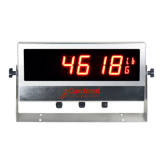
- Page 1 Remote Display INSTALLATION MANUAL 3601-M511-O1 Rev C 203 E. Daugherty, Webb City, MO 64870 USA Printed in USA Ph: 417-673-4631 • Fax: 417-673-2153 07/16 www.cardinalscale.com Technical Support: Ph: 866-254-8261 • tech@cardet.com 3601-M511-O1 Rev C • RD2 Series...
- Page 2 3601-M511-O1 Rev C • RD2 Series...
-
Page 3: Table Of Contents
DATE OF PURCHASE _________________ PURCHASED FROM __________________ ____________________________________ ____________________________________ ____________________________________ RETAIN THIS INFORMATION FOR FUTURE USE PRECAUTIONS Before using this instrument, read this manual and pay special attention to all "WARNING" symbols: ELECTRICAL STATIC IMPORTANT WARNING SENSITVE 3601-M511-O1 Rev C • RD2 Series... - Page 4 Seller is not able to guarantee the result of any procedure contained herein. Nor can they assume responsibility for any damage to property or injury to persons occasioned from the procedures. Persons engaging the procedures do so entirely at their own risk. 3601-M511-O1 Rev C • RD2 Series...
-
Page 5: Introduction
INTRODUCTION Thank you for your purchase of our Cardinal RD2 Remote Display. It was built with Cardinal quality and reliability. This manual will guide you through installation, and operation of your display. Please read it thoroughly before attempting to install your display. Also, make certain that you pay attention to the warnings that appear in this manual. -
Page 6: Auto-Format Feature
SITE PREPARATION Electrical Power The RD2 display has been designed to operate from 94 to 264 VAC at 47/63 Hz. Note that a special order is not required for operation at 230 VAC. WARNING! To avoid electrical hazard and possible damage to the display, DO NOT, under any circumstance, cut, remove, alter, or in any way bypass the power cord-grounding prong. -
Page 7: Installation
Mounting The RD2 display is housed in a stainless steel wall or desk-mount enclosure. The gimbal may be mounted on a desktop or other smooth, flat, horizontal surface or may be mounted on a wall. Refer to Figure No. 1 for a layout of wall-mounting bolts. -
Page 8: Serial Cable Installation
Tighten the screw to secure the wire in place. Figure No. 4 Figure No. 5 RD2 PASSIVE END RD2 ACTIVE END IMPORTANT! A jumper must be installed between P4 terminals 1 and 7 to enable 20mA current loop operation. 3601-M511-O1 Rev C • RD2 Series... -
Page 9: 20Ma Current Loop Connections
SERIAL CABLE INSTALLATION, CONT. CURRENT Cardinal Indicators 20mA Current Loop Connections 190/190A (with 190-RS232 Option Card) CARD (PASSIVE) P4,6 P4, 6 P4,7 P4, 9 JUMPER P4, 4 to 5 JUMPER P4, 1 to 7 PORT 1 PORT 2 P3, 3... -
Page 10: Legacy Cardinal Indicators
SERIAL CABLE INSTALLATION, CONT. CURRENT Cardinal Indicators 20mA Current Loop Connections, Cont. PORT 2 (ACTIVE) PORT 2 (PASSIVE) P21, 2 P4, 5 P21, 1 P4, 6 P21, 5 P4, 6 P21, 2 P4, 9 J3 INSTALLED J3 REMOVED JUMPER J7 SHUNT:20mA... - Page 11 SERIAL CABLE INSTALLATION, CONT. LEGACY Cardinal Indicators 20mA Current Loop Connections, Cont. 225 (without USB) PORT 1 (ACTIVE) PORT 1 (PASSIVE) P14, 3 P4, 5 P14, 4 P4, 6 P14, 4 P4, 6 P14, 5 P4, 9 JUMPER JUMPER P14, 5 to P14, 8...
-
Page 12: Display Board
P4 = SERIAL 9 terminal connector for serial cable connections. P5 = IIC Bus (For Factory Use Only) JUMPERS J1 =Operation mode selection jumper. (Jumper must be on pins 2 and 3 for scoreboard) 3601-M511-O1 Rev C • RD2 Series... -
Page 13: Setup And Configuration
SETUP AND CONFIGURATION The RD2 display has been pre-configured at the factory and should not require configuration for use in most applications. In the event that the factory settings do not meet the requirements of your application, the following describes the steps to configure the display. -
Page 14: Display Brightness
1 = 8 Data bits DISPLAY BRIGHTNESS The RD2 Remote Display has an extra-bright 2 1/4” LED display. Ten levels of brightness can be set using the Up Arrow and Right Arrow switches on the display board. To Increase Brightness: 1. -
Page 15: Annunicator Display
It is displayed in the lower character of the annunciator display. is turned on to show that the displayed weight is the Tare weight. It is displayed in the lower character of the annunciator display. 3601-M511-O1 Rev C • RD2 Series... -
Page 16: Single And Multiple Display Connections
The RD2 can display received characters from a single weight indicator. With multiple displays, the received characters can be echoed form one RD2 to other RD2 displays allowing the same weight data to be shown on two or more displays. Typical applications of multiple displays might consist of back to back displays or displays placed at each end of the scale. -
Page 17: Error And Status Displays
ERROR AND STATUS DISPLAYS The RD2 Remote Display is equipped with software that tests various portions of its circuitry and verifies proper operation. Should a problem be detected, a message will be displayed. The following lists the messages displayed and their meaning:... -
Page 18: Part Identification
CABLE: AC POWER W/FILTER 205/210 DWI 8200-C363-08 POWER SUPPLY COVER 8200-D278-0A PCB ASSY: DISPLAY BOARD, 210-FE 8200-D286-08 OVERLAY: 210-FE LABEL CAUTION HIGH VOLTAGE 8510-C346-OI 8200-C298-08 GIMBAL, 210-FE 6540-1053 ENCLOSURE KNOB 3601-B510-08 GIMBAL SPACER 6540-1004 RUBBER FOOT (NOT SHOWN) 3601-M511-O1 Rev C • RD2 Series... - Page 19 PART IDENTIFICATION, CONT. 3601-M511-O1 Rev C • RD2 Series...
- Page 20 PART IDENTIFICATION, CONT. 3601-M511-O1 Rev C • RD2 Series...
- Page 21 PART IDENTIFICATION, CONT. 3601-M511-O1 Rev C • RD2 Series...
- Page 22 STATEMENT OF LIMITED WARRANTY WARRANTY TERMS Cardinal Scale Manufacturing Company warrants the equipment we manufacture against defects in material and workmanship. The length and terms and conditions of these warranties vary with the type of product and are summarized below:...
- Page 23 This warranty sets forth the extent of our liability for breach of any warranty or deficiency in connection with the sale or use of our product. Cardinal will not be liable for consequential damages of any nature, including but not limited to loss of profit, delays or expenses, whether based on tort or contract.
- Page 24 3601-M511-O1 Rev C • RD2 Series...
Need help?
Do you have a question about the RD2 and is the answer not in the manual?
Questions and answers