
Related Manuals for Cardinal SB555


Summary of Contents for Cardinal SB555
- Page 1 SB555 Remote Display With Traffic Light Installation and Technical Manual 3601-0816-0M Rev A SB555 Installation and Technical Manual...
- Page 2 3601-0816-0M Rev A SB555 Installation and Technical Manual...
-
Page 3: Table Of Contents
Communication Interface Cable Color Code and Terminal Block Details ... Page 16 TROUBLESHOOTING ……………………………………………………………… Page 17 PRECAUTIONS Before using this instrument, read this manual and pay special attention to all "WARNING" symbols: ELECTRICAL STATIC IMPORTANT WARNING SENSITVE 3601-0816-0M Rev A SB555 Installation and Technical Manual... - Page 4 Seller is not able to guarantee the result of any procedure contained herein. Nor can they assume responsibility for any damage to property or injury to persons occasioned from the procedures. Persons engaging in the procedures do so entirely at their own risk. 3601-0816-0M Rev A SB555 Installation and Technical Manual...
-
Page 5: Introduction
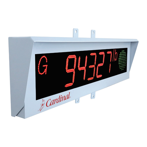
INTRODUCTION Thank you for your purchase of our Cardinal SB555 Remote Display with Traffic Light. This manual will guide you through the installation and operation of your display. Please read it thoroughly before attempting to install your display. Also, make certain that you pay attention to the warnings that appear in this manual. -
Page 6: Features
5-inch (12.7 cm) high Red/Green traffic light. The SB555 can mirror the display every five (5) seconds allowing the weight to be seen in vehicle mirrors when leaving the scale. Linked multiple displays for viewing multiple axles and total weight simultaneously. -
Page 7: Site Preparation
SITE PREPARATION Electrical Power The SB555 has been designed to operate from 115 to 230V AC at 50/60 Hz. Note that at 120V AC, the SB555 power consumption is 100 mA (12 watts). WARNING! To avoid electrical hazards and possible damage to the SB555 remote display, DO NOT, under any circumstance, cut, remove, alter, or in any way bypass the power cord grounding prong. -
Page 8: Installation
Overview The SB555 has an ambient light sensor located at the bottom of the enclosure. Also located on the bottom of the enclosure is the Configuration Switch Access Panel, with the gland connectors for the AC Power Cord, Communication Interface Cable, and Communication Cable Standby Port. -
Page 9: Mounting
INSTALLATION, CONT. Mounting The SB555 remote display is normally mounted on a wall or other vertical surface. The remote display is attached to the wall with four (4) bolts. Refer to Figure No. 3 for the mounting hole layout. First, make sure the mounting surface is strong enough to support the display. Carefully lay out the mounting hole locations and then drill and install the anchor bolts. -
Page 10: Sb555 Configuration
NOTE: 20mA Current Loop is limited to 9600 bps. MIRROR SETTING – (KEY 2) The Mirror setting allows the user to specify if the SB555 remote display will switch back and forth between a normal display and a mirror image display every five seconds. -
Page 11: Baud Rate Setting - (Key 2)
BAUD RATE SETTING – (KEY 2) The Baud Rate setting for the SB555 remote display is set using dip switches 2, and 3 of the switches labeled KEY 2. Allowable baud rates are 2400 to 19,200. NOTE: 20mA Current Loop is limited to 9600 bps. -
Page 12: Number Of Digits Displayed In The Data - (Key 4)
SB555 CONFIGURATION, CONT. NUMBER OF DIGITS DISPLAYED IN THE DATA – (KEY 4) The number of digits displayed in the data setting for the SB555 remote display is set using dip switches 3, 4, and 5 of the switches labeled KEY 4. -
Page 13: 20Ma Current Loop Connections
Pin 2, CH2, CL RX- JUMPER P16, 3 to P16, 9 PORT 2 (ACTIVE) SB555 P21, 2 Pin 1, CH1, CL RX+ P21, 5 Pin 2, CH2, CL RX- J3 INSTALLED J7 SHUNT:20mA 3601-0816-0M Rev A SB555 Installation and Technical Manual... -
Page 14: Legacy Cardinal Indicators
Pin 1, CH1, CL RX+ P18, 13 Pin 2, CH2, CL RX- 778C 778C (ACTIVE) SB555 COMA, 10 Pin 1, CH1, CL RX+ COMA, 11 Pin 2, CH2, CL RX- JUMPER COMA, 23 to COMA, 24 3601-0816-0M Rev A SB555 Installation and Technical Manual... -
Page 15: Serial Data Format Details
NOTE: Before communication between two devices, please ensure that the Parity Bit, Data Bits, Baud Rate, and RS232 port format are correctly selected. In normal operating mode, the SB555 remote display will display the weight value sent by the weigh indicating instrument. -
Page 16: Rice Lake Iq355
Start of Text (hex 02) swa =, swb =, swc = Status Bytes xxxxxx = Displayed Weight, Gross, or Net Weight (Six Digits) cr = Carriage Return (hex 0D) sum = Checksum Character 3601-0816-0M Rev A SB555 Installation and Technical Manual... -
Page 17: Sb500 (With Traffic Light)
The following is an example of an SB500 (with Traffic Light) serial data format output for a multi-scoreboard installation. This illustrated command is as follows: %94327lbGG<CR>%1 – 1267lbGR<CR>%30012567kgN<CR> Display 0, 1 display in the row displays its portion of the command: %94327lbGG<CR> 3601-0816-0M Rev A SB555 Installation and Technical Manual... -
Page 18: Beltway Integrator
The number of digits displayed in the data string is set using dip switches 3, 4, and 5 of the switches labeled KEY 4. Refer to Figure No. 6. Data Displayed Switch 3 Switch 4 Switch 5 -12345678.123 -12345678.123 -12345678.123 -12345678.123 -12345678.123 -12345678.123 -12345678.123 3601-0816-0M Rev A SB555 Installation and Technical Manual... -
Page 19: Multiple Displays
MULTIPLE DISPLAYS The SB555 remote display has been designed to be linked to other SB555 displays allowing multiple lines of weight data to be displayed while being driven by a single serial port on the weight indicating instrument. Typical applications might consist of three displays showing Gross, Net, and Tare weights from a single indicator or four displays showing the weight from each of three platforms and a total weight also from a single weight indicator. -
Page 20: Indicator Connections
The SB555 remote display is equipped with a 16-foot (4.9 m) communication interface cable terminated with a DB9 to connect to a Cardinal weight indicator or most weight indicators from other manufacturers. The SB555 remote display can be configured for either RS232 or RS485 with the baud rate selectable from 2400 to 19.2k, or 20mA Current Loop with the baud rate... -
Page 21: Troubleshooting
TROUBLESHOOTING The SB555 Remote Display is equipped with software that tests various portions of its circuitry and verifies proper operation when powered ON. Should a problem be detected, a message will be displayed. The following lists the messages displayed and their meaning:... - Page 22 First warranty page 3601-0816-0M Rev A SB555 Installation and Technical Manual...
- Page 23 Second warranty page 3601-0816-0M Rev A SB555 Installation and Technical Manual...
- Page 24 Cardinal Scale Mfg. Co. 102 E. Daugherty, Webb City, MO 64870 USA Ph: 417-673-4631 or 1-800-641-2008 Fax: 417-673-2153 www.cardinalscale.com Technical Support: 1-866-254-8261 E-mail: tech@cardet.com 3601-0816-0M Rev A 08/23 3601-0816-0M Rev A SB555 Installation and Technical Manual...
Need help?
Do you have a question about the SB555 and is the answer not in the manual?
Questions and answers