Avnet MaaXBoard Mini Hardware User Manual
Hide thumbs
Also See for MaaXBoard Mini:
- User manual (59 pages) ,
- User manual (50 pages) ,
- User manual (39 pages)
Table of Contents
Advertisement
Quick Links
Advertisement
Table of Contents

Related Manuals for Avnet MaaXBoard Mini


Summary of Contents for Avnet MaaXBoard Mini
- Page 1 MaaXBoard Mini Hardware User Manual V0.0...
- Page 2 MaaXBoard Mini HW UserManual V0.0 Copyright Statement: The MaaXBoard Mini single board computer and its related intellectual property are owned by Avnet Manufacturing Services. Avnet Manufacturing Services has the copyright of this document and reserves all rights. Any part of the document should not be modified, distributed or duplicated in any approach and form with the written permission issued by Avnet Manufacturing Services.
-
Page 3: Revision History
MaaXBoard Mini HW UserManual V0.0 Revision History Rev. Description Author Date Initial version Hugo 20191030 V0.0 http://www.embest-tech.com... -
Page 4: Table Of Contents
Product Dimensions (mm) ....................12 1.8 Height Distribution (mm) ....................13 Chapter 2 Introduction of Hardware System ..................14 2.1 MaaXBoard Mini Hardware Installation and Start up ............14 2.1.1 Installation ........................14 2.1.2 Booting Configuration ....................14 2.2 Details of Interfaces ......................15 ... - Page 5 MaaXBoard Mini HW UserManual V0.0 2.2.10 Extend Interface J5 ..................... 35 2.2.11 MIPI-DSI ........................36 2.3 Introduction of Peripheral Chips ..................39 2.3.1 AR8035 ........................39 2.3.2 BD71837 ........................39 2.3.3 AW-CM256SM ......................39 Chapter 3 Appendix ..........................40 3.1 ...
- Page 6 MaaXBoard Mini HW UserManual V0.0 Figure Figure 1.1 MaaXBoard Mini System Block Diagram ................8 Figure 1.2 MaaXBoard Mini Top View ....................11 Figure 1.3 MaaXBoard Mini Bottom View ..................11 Figure 1.4 Product Dimensions ......................12 Figure 1.5 Height Distribution ......................13 ...
- Page 7 MaaXBoard Mini HW UserManual V0.0 Table Table 2.3 Ethernet Interface Pin Definition ..................20 Table 2.4 Camera Connector Pin Definition ..................23 Table 2.5 40 Pin Expansion Pin Header Definition ................26 Table 2.6 Antenna Connector Pin Definition ..................30 ...
-
Page 8: Chapter 1 Product Overview
Chapter 1 Product Overview 1.1 Brief Introduction MaaXBoard Miniis a development board for makers, designed by Avnet Manufacturing Services. The MaaXBoard Miniis a single board computer based on NXP IMX8MMini SOC series, which can be used for the areas such as medical instruments, video surveillance, communications, IOT, makers and so on. -
Page 9: Packing List
MaaXBoard Mini HW UserManual V0.0 1.3 Packing List 1 ×MaaXBoard Mini 1 × Desiccant 1 × Anti-static Bag 1 × Safety Flyer 1 × Quick Start Guide 1 × Box 1.4 Product Specifications General Specifications: Operating Temperature: 0~70°C (When the CPU loads heavy, need a heatsink) -
Page 10: Other Customer Provide Parts
MaaXBoard Mini HW UserManual V0.0 1.5 Other Customer Provide Parts To use the various functions of MaaXBoard Mini, customer should also provide the following parts which are not contained in MaaXBoard Mini Packages. 1 × USB to serial cable (TTL) 1 ×... -
Page 11: Interface Locations
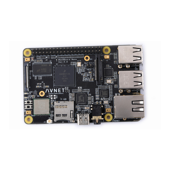
MaaXBoard Mini HW UserManual V0.0 1.6 Interface Locations Figure 1.2MaaXBoard Mini Top View Figure 1.3MaaXBoard Mini Bottom View http://www.embest-tech.com... -
Page 12: Product Dimensions(Mm)
MaaXBoard Mini HW UserManual V0.0 1.7 Product Dimensions(mm) Figure 1.4Product Dimensions http://www.embest-tech.com... -
Page 13: Height Distribution (Mm)
MaaXBoard Mini HW UserManual V0.0 1.8 Height Distribution (mm) Figure 1.5Height Distribution Note: There is tolerance in height due to mechanical treatment. http://www.embest-tech.com... -
Page 14: Chapter 2 Introduction Of Hardware System
2.1 MaaXBoard Mini Hardware Installation and Start up 2.1.1 Installation Before power up MaaXBoard Mini, you need to connect all necessary peripheral devices, then power on the board. 2.1.2 Booting Configuration According to the manufactured configuration, MaaXBoard Mini supports two boot mode: boot from Micro SD card or boot from eMMC. -
Page 15: Details Of Interfaces
2.2.1 POWER IN MaaXBoard Mini use a USB Type C interface as the +5V power in. Note that the USB Type C interface only provides power supply function, do not support data communication. The Power adapter should support 3A or above current output. -
Page 16: Button
MaaXBoard Mini HW UserManual V0.0 2.2.2 Button There are 3 buttons on the MaaXBoard Mini, S3 as the system power button for the board, S1 and S2 as user button. Figure 2.2Button http://www.embest-tech.com... -
Page 17: Usb Host
MaaXBoard Mini HW UserManual V0.0 2.2.3 USB Host MaaXBoard Mini provides twoDouble-layer USB Host connector (J2,J4), the USB portscan provide full speed USB2.0 data communication function, used to extend external devices in USB protocol. Figure 2.3 Double-layer USB Host connector... - Page 18 MaaXBoard Mini HW UserManual V0.0 Table 2.1 USB Pin Definition USB Connector(J2) Signal Description Ball Description Signal Type VBUS1 Down layer 5V Power USB1 PHY USB2.0 differential signal USB1_HOST_DN pair negative Differential signal USB1 PHY USB2.0 differential signal USB1_HOST_DP pair positive...
- Page 19 MaaXBoard Mini HW UserManual V0.0 Table 2.2USB Pin Definition USB Connector(J4) Signal Description Ball Description Signal Type VBUS Down layer 5V Power USB2.0 host differential signal pair USB_HOST_DN negative Differential signal USB2.0 host differential signal pair USB_HOST_DP positive Down layer ground...
- Page 20 MaaXBoard Mini HW UserManual V0.0 2.2.4 RJ-45 J8 is the physical interface of Gigabit Ethernet, the interface information is shown in the following picture: Figure 2.4RJ45 Connector Table 2.1 Ethernet Interface Pin Definition RJ45 Ethernet( J8) Signal Name Ball Description...
- Page 21 MaaXBoard Mini HW UserManual V0.0 RJ45 Ethernet( J8) Signal Name Ball Description Signal Type No connection No connection MIIA_TRP2 Media-dependent interface 2 positive MIIA_TRN2 Media-dependent interface 2 negative Differential signal MIIA_TRP3 Media-dependent interface 3 positive MIIA_TRN3 Media-dependent interface 3 negative...
-
Page 22: Camera
MaaXBoard Mini HW UserManual V0.0 2.2.5 Camera J3 on the MaaXBoard Mini is a 15-pin FPC connector that supports MIPI 2Lane Camera input. The following picture shows the information of J3: Figure 2.5Camera Connector http://www.embest-tech.com... - Page 23 MaaXBoard Mini HW UserManual V0.0 Table 2.2 Camera Connector Pin Definition Camera(J3) Signal Ball Signal Type Description Ground MIPI CSI received differential signal 0 pair CSI_DN0 negative Differential signal MIPI CSI received differential signal 0 pair CSI_DP0 positive Ground MIPI CSI received differential signal 1 pair...
- Page 24 MaaXBoard Mini HW UserManual V0.0 Camera(J3) I2C1_SDA I2C1 data NVCC_3V3 Power No connection No connection No connection No connection No connection No connection No connection No connection No connection No connection No connection No connection No connection No connection No connection...
-
Page 25: Pin Expansion Pin Header
MaaXBoard Mini HW UserManual V0.0 2.2.6 40Pin Expansion Pin Header J1 on the MaaXBoard Mini is a 40 pin Extend Interface, used to support external devices. The following picture shows the information of the 40 Pins expansion connector J1: Figure 2.62.54mm Double Row Pin Header... - Page 26 MaaXBoard Mini HW UserManual V0.0 Figure 2.740Pin Pin Header Pin1 Position Table 2.3 40 Pin Expansion Pin Header Definition Expansion(J1) Signal Ball Signal Type Description NVCC_3V3 3.3V/500mA output Power 5V_IN 5V power supply input or output Power I2C2_SDA General-purpose input/output...
- Page 27 MaaXBoard Mini HW UserManual V0.0 Expansion(J1) GPIO1_IO14 General-purpose input/output UART1_TXD General-purpose input/output Ground Ground UART1_RXD General-purpose input/output GPIO3_IO17 General-purpose input/output SAI3_TXC General-purpose input/output GPIO3_IO04 General-purpose input/output UART5 transmit Data Ground GPIO3_IO18 General-purpose input/output UART2_RXD General-purpose input/output NVCC_3V3 3.3V/500mA output Power...
- Page 28 MaaXBoard Mini HW UserManual V0.0 Expansion(J1) Ground Ground GPIO1_IO01 AF14 General-purpose input/output I2C3_SDA General-purpose input/output I2C3_SCL General-purpose input/output GPIO1_IO15 General-purpose input/output Ground Ground SAI2_MCLK AD19 General-purpose input/output GPIO5_IO05 General-purpose input/output GPIO5_IO04 General-purpose input/output Ground Ground SAI3_RXFS General-purpose input/output GPIO3_IO16 General-purpose input/output...
-
Page 29: Wi-Fi/Bluetooth (Optional)
MaaXBoard Mini HW UserManual V0.0 2.2.7 Wi-Fi/Bluetooth (Optional) MaaXBoard Miniemploys a Wi-Fi/Bluetooth module to support Wi-Fi 2.4G/5GFrequency, and Bluetooth V4.2 standard. The Wi-Fi/Bluetooth antennas have two type: onboard ceramic antenna or IPEX antenna. IPEX antenna (customized version) IPEX antenna is empty welding in default, if the customer needs to use this interface, please contact the Avnet Manufacturing Services to customize. - Page 30 MaaXBoard Mini HW UserManual V0.0 Table 2.4 Antenna Connector Pin Definition Antenna(J10) Signal Description Ball Signal Type Data transmit Antenna Ground Onboard Ceramic Antenna (Default) Onboard Ceramic Antenna’s specification as follows: Figure 2.9 Onboard Ceramic Antenna http://www.embest-tech.com...
-
Page 31: Micro Sd Card (Tf Card)
MaaXBoard Mini HW UserManual V0.0 2.2.8 Micro SD Card (TF Card) Micro SD card(TF Card) is used to start the code, the program system curing storage, or provide external storage function. Figure 2.3 Micro SD Card Slot http://www.embest-tech.com... - Page 32 MaaXBoard Mini HW UserManual V0.0 Table 2.5Micro SD Card Slot Pin Definition TF card connector(J9) Signal Description Ball Signal Type SD1_ DATA2 MMC Data bit2 SD1_ DATA3 MMC Data bit3 SD1_CMD MMC command NVCC_3V3 3.3V power supply Power SD1_CLK MMC reference clock...
-
Page 33: Extend Interface J6
MaaXBoard Mini HW UserManual V0.0 2.2.9 Extend Interface J6 J6on the MaaXBoard Mini is a 12 pin Wafer connector, used to support GPIO function. The following picture shows the information of the 12 pin Wafer connector J6: Figure 2.412Pin Wafer Connector... - Page 34 MaaXBoard Mini HW UserManual V0.0 Table 2.612Pin Definition Expansion Interface1 (J6) Signal Ball Description Signal Type SAI1_MCLK AB18 SAI1 master clock output Ground Ground SAI1_TXD7 AF23 SAI1 transmit data bit7 SAI1_TXD6 AG23 SAI1 transmit data bit6 SAI1_TXD5 AF22 SAI1 transmit data bit5...
- Page 35 MaaXBoard Mini HW UserManual V0.0 2.2.10 Extend Interface J5 J5 on the MaaXBoard Mini is a 12 pins Wafer connector, used to support GPIO function. The following picture shows the information of the 12 pins Wafer connector J5: Figure 2.5 12Pin Wafer Connector Table 2.7 J23 Pin Definition...
- Page 36 AF16 SAI1 receive bit clock 2.2.11 MIPI-DSI J7 on the MaaXBoard Mini is a 30 pin FPC connector that supports MIPI-DSI high-definition and small size screen. The following picture shows the information of 30-pin FPC connector J7: Figure 2.630Pin FPC Connector (MIPI-DSI)
- Page 37 MaaXBoard Mini HW UserManual V0.0 Table 2.8J7 Pin Definition 30Pin FPC Connector (J7) Signal Ball Description Signal Type Ground Ground DSI_DP3 MIPI DSI transmit differential signal 3 pair Differential output DSI_DN3 MIPI DSI transmit differential signal 3 pair Ground Ground...
- Page 38 MaaXBoard Mini HW UserManual V0.0 30Pin FPC Connector (J7) No connection No connection Ground Ground No connection VSYS 5V power output Power VSYS 5V power output VSYS 5V power output http://www.embest-tech.com...
- Page 39 MaaXBoard Mini HW UserManual V0.0 2.3 Introduction of Peripheral Chips 2.3.1 AR8035 AR8035 Integrated 10/100/1000 Mbps Ethernet Transceiver. The AR8035 is a single port 10/100/1000 Mbps Tri-speed Ethernet PHY, which provides a low power, low BOM (Bill of Materials) cost solution for comprehensive applications including consumer, enterprise, carrier and home networks, etc.
- Page 40 MaaXBoard Mini HW UserManual V0.0 Chapter 3 Appendix 3.1 Software MaaXBoard Mini support Linux Yoctosystem and Android system, for the detail software introduction, please refer to related user manual. Linux MaaXBoard Mini Linux Software Release Note MaaXBoard Mini Linux Software User Manual...
- Page 41 4.2 Warranty Conditions 12-month free warranty on the PCB under normal conditions of use since the sales of the product; The following conditions are not covered by free services; Avnet Manufacturing Services will charge accordingly: Customers fail to provide valid purchase vouchers or the product identification tag is damaged, unreadable, altered or inconsistent with the products;...
- Page 42 Products purchased from unauthorized sales; Warranty (including verbal and written) that is not made by Avnet Manufacturing Services and not included in the scope of our warranty should be fulfilled by the party who committed. Avnet Manufacturing Services has no any responsibility.
- Page 43 MaaXBoard Mini HW UserManual V0.0 Chapter 5 Contact Information Tel: +86-755-33190846/33190847/33190848 E-mail: Technical support: support@embest-tech.com Sales contact: chinasales@embest-tech.com Fax: +86-755-25616057 Website: http://www.embest-tech.com/ Address: Tower B 4/F, Shanshui Building, NanshanYungu Innovation Industry Park, Liuxian Ave.No.4093,Nanshan District, Shenzhen, Guangdong, China http://www.embest-tech.com...
- Page 44 MaaXBoard Mini HW UserManual V0.0 Federal Communications Commission (FCC) Statement This device complies with part 15 of the FCC Rules. Operation is subject to the following two conditions: (1) This device may not cause harmful interference, and (2) this device must accept any interference received, including interference that may cause undesired operation.
- Page 45 MaaXBoard Mini HW UserManual V0.0 RF exposure statement: The transmitter must not be colocated or operated in conjunction with any other antenna or transmitter. This equipment complies with the FCC RF radiation exposure limits set forth for an uncontrolled environment. This equipment should be installed and operated with a minimum distance of 20cm between the radiator and any part of your body.
Need help?
Do you have a question about the MaaXBoard Mini and is the answer not in the manual?
Questions and answers