Avnet MaaXBoard AES-MC-SBC-IMX8M-G Hardware User Manual
Hide thumbs
Also See for MaaXBoard AES-MC-SBC-IMX8M-G:
- User manual (56 pages) ,
- User manual (50 pages)
Table of Contents
Advertisement
Advertisement
Table of Contents

Related Manuals for Avnet MaaXBoard AES-MC-SBC-IMX8M-G


Summary of Contents for Avnet MaaXBoard AES-MC-SBC-IMX8M-G
- Page 1 MaaXBoard (AES-MC-SBC-IMX8M-G) Hardware User Manual V1.1...
-
Page 2: Copyright Statement
Avnet Manufacturing Services. Avnet Manufacturing Services has the copyright of this document and reserves all rights. Any part of the document should not be modified, distributed or duplicated in any approach and form with the written permission issued by Avnet Manufacturing Services. -
Page 3: Revision History
MaaXBoard HW UserManual V1.1 Revision History Rev. Description Author Date V0.0 Initial version Hugo 20190430 V1.0 Update description Hugo 20190815 V1.1 Update block diagram, picture and description Hugo 20191121 http://www.avnet.me/maaxboard... - Page 4 2.2.5 RJ-45..........................21 2.2.6 Camera ........................23 2.2.7 40 Pin Expansion Pin Header ..................26 2.2.8 Wi-Fi/Bluetooth (Optional) ................... 30 2.2.9 Micro SD Card (TF Card)..................... 32 2.2.10 Extend Interface J26 ....................34 2.2.11 Extend Interface J23 ....................36 http://www.avnet.me/maaxboard...
- Page 5 MaaXBoard HW UserManual V1.1 2.2.12 MIPI-DSI ........................37 Introduction of Peripheral Chips ................... 40 2.3.1 AR8035 ........................40 2.3.2 BD71837 ........................40 2.3.3 AW-CM256SM ......................40 Software..........................41 Technical Support ......................... 42 Warranty Conditions ......................42 http://www.avnet.me/maaxboard...
- Page 6 Figure 2.9 IPEX Antenna Connector ....................30 Figure 2.10 Onboard Ceramic Antenna ....................31 Figure 2.11 Micro SD Card Slot ......................32 Figure 2.12 12Pin Wafer Connector ....................34 Figure 2.13 12Pin Wafer Connector ....................36 Figure 2.14 30 Pin FPC Connector (MIPI-DSI) .................. 37 http://www.avnet.me/maaxboard...
- Page 7 Table 2.5 40 Pin Expansion Pin Header Definition ................27 Table 2.6 Antenna Connector Pin Definition ..................30 Table 2.7 Micro SD Card Slot Pin Definition ..................33 Table 2.8 12Pin Definition ........................35 Table 2.9 J23 Pin Definition ........................ 36 Table 2.10 J16 Pin Definition ......................38 http://www.avnet.me/maaxboard...
-
Page 8: Chapter 1 Product Overview
Chapter 1 Product Overview 1.1 Brief Introduction MaaXBoard is a development board for makers, designed by Avnet Manufacturing Services. The MaaXBoard is a single board computer based on NXP IMX8M SOC series, which can be used for the areas such as medical instruments, video surveillance, communications, IOT, makers and so on. -
Page 9: Packing List
1 × 8bits and 1x 7bits GPIO Interface (Support Audio peripheral expand) 1 × HDMI 2.0 Interface 1 × Power Interface (USB Type C Connector) 1 × Power Button 2 × User Button 1 × Wi-Fi/Bluetooth 2 × User LED http://www.avnet.me/maaxboard... - Page 10 1 × USB to serial cable (TTL) 1 × 1Gbps Network Cable 1 × Camera Module 1 × MIPI-DSI Displayer 1 × 5V/3A Power Supply (USB Type C Interface) 1 × HDMI Cable 1 × HDMI Displayer Other tools needed to implement related function http://www.avnet.me/maaxboard...
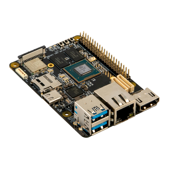
- Page 11 MaaXBoard HW UserManual V1.1 1.6 Interface Locations Figure 1.2 MaaXBoard Top View Figure 1.3 MaaXBoard Bottom View http://www.avnet.me/maaxboard...
-
Page 12: Product Dimensions (Mm)
MaaXBoard HW UserManual V1.1 1.7 Product Dimensions (mm) Figure 1.4 Product Dimensions http://www.avnet.me/maaxboard... - Page 13 MaaXBoard HW UserManual V1.1 1.8 Height Distribution (mm) Figure 1.5 Height Distribution Note: There is tolerance in height due to mechanical treatment. http://www.avnet.me/maaxboard...
-
Page 14: Chapter 2 Introduction Of Hardware System
SD Card foot print and eMMC footprint are on top of each other so only one or the other can be populated at the same time. If interested in eMMC configuration, Avnet does offer BOM customization services to populated the eMMC footprint over the SD Card footprint. Contact customize@avnet.com... - Page 15 MaaXBoard use a USB Type C interface as the +5V power in. Note that the USB Type C interface only provides power supply function, do not support data communication. The Power adapter should support 3A or above current output. Figure 2.1 USB Type C Slot http://www.avnet.me/maaxboard...
- Page 16 MaaXBoard HW UserManual V1.1 2.2.2 Button There are 3 buttons on the MaaXBoard, S2 as the system power button for the board, S3 and S4 as user button. Figure 2.2 Button http://www.avnet.me/maaxboard...
- Page 17 Powerful video display is an important feature of MaaXBoard. The HDMI 2.0 interface support up to 4096 x 2160 at 60Hz display output. J9 is the interface for connecting an HDMI display device on the MaaXBoard, which is a standard HDMI 19Pin connector. Its specification and dimension as follows: Figure 2.3 HDMI Connector http://www.avnet.me/maaxboard...
- Page 18 HDMI clock differential negative Differential Data HDMI_CEC HDMI consumer electronic control No Connection HDMICONN_I2CSCL HDMI display data channel clock HDMICONN_I2CSDA HDMI display data channel data Ground Ground 5V_VDD Power HDMICONN_HPLG HDMI display hot plug detect GND_SHELDS GND_SHELDS Ground GND_SHELDS GND_SHELDS http://www.avnet.me/maaxboard...
- Page 19 MaaXBoard provides a Double-layer USB Host connector (J5), the two USB port are two independent controllers, and each one could provide full speed USB3.0 data communication function, used to extend external devices in USB protocol. Figure 2.4 Double-layer USB Host connector http://www.avnet.me/maaxboard...
- Page 20 Differential signal USB2 PHY USB3.0 received differential signal pair USB2_HOST_RXP positive Ground USB2 PHY USB3.0 transmit differential signal pair USB2_HOST_TXN Differential signal negative USB2 PHY USB3.0 transmit differential signal pair USB2_HOST_TXP Differential signal positive Case Earth Earth Ground http://www.avnet.me/maaxboard...
- Page 21 USB Connector(J5) Signal Name Ball Description Signal Type Case Earth Case Earth Earth Ground Case Earth 2.2.5 RJ-45 J13 is the physical interface of Gigabit Ethernet, the interface information is shown in the following picture: Figure 2.5 RJ45 Connector http://www.avnet.me/maaxboard...
- Page 22 Media-dependent interface 2 negative Differential signal MIIA_TRP3 Media-dependent interface 3 positive MIIA_TRN3 Media-dependent interface 3 negative MIIA_LED_LINK/ Pull-up Parallel LED output for data transmit Pull-down/ MIIA_LED_LINK MIIA_LED_ACT Parallel LED output for 10/100/1000 BASE-T activity, active blinking Pull-up Ground Ground Ground http://www.avnet.me/maaxboard...
- Page 23 MaaXBoard HW UserManual V1.1 2.2.6 Camera J12 on the MaaXBoard is a 30-pin FPC connector that supports MIPI 2Lane Camera input. The following picture shows the information of J12: Figure 2.6 Camera Connector http://www.avnet.me/maaxboard...
- Page 24 Ground GPIO3_IO18 Output for powering sensor Output GPIO3_IO14 Output for resetting sensor Output I2C1_SCL I2C1 clock output Output I2C1_SDA I2C1 data NVCC_3V3 Power No connection No connection No connection No connection No connection No connection No connection No connection http://www.avnet.me/maaxboard...
- Page 25 MaaXBoard HW UserManual V1.1 Camera(J12) Signal Name Ball Description Signal Type No connection No connection No connection No connection No connection No connection No connection http://www.avnet.me/maaxboard...
- Page 26 2.2.7 40 Pin Expansion Pin Header J10 on the MaaXBoard is a 40 pin Extend Interface, used to support external devices. The following picture shows the information of the 40 Pin expansion connector J10: Figure 2.7 2.54mm Double Row Pin Header http://www.avnet.me/maaxboard...
- Page 27 NVCC_3V3 3.3V/500mA output Power 5V_IN 5V power supply input or output Power I2C2_SDA General-purpose input/output 5V_IN 5V power supply input or output Power I2C2_SCL General-purpose input/output Ground Ground GPIO3_IO16 General-purpose input/output UART1_TXD General-purpose input/output Ground Ground UART1_RXD General-purpose input/output http://www.avnet.me/maaxboard...
- Page 28 ECSPI1_MISO General-purpose input/output GPIO3_IO15 General-purpose input/output ECSPI1_SCLK General-purpose input/output ECSPI1_SS0 General-purpose input/output Ground Ground GPIO3_IO02 General-purpose input/output I2C3_SDA General-purpose input/output I2C3_SCL General-purpose input/output GPIO3_IO05 General-purpose input/output Ground Ground GPIO3_IO10 General-purpose input/output GPIO1_IO15 General-purpose input/output GPIO1_IO13 General-purpose input/output Ground Ground http://www.avnet.me/maaxboard...
- Page 29 MaaXBoard HW UserManual V1.1 Expansion(J10) Signal Name Ball Description Signal Type SAI2_RXFS General-purpose input/output GPIO1_IO03 General-purpose input/output GPIO3_IO11 General-purpose input/output SAI2_RXD General-purpose input/output Ground Ground SAI2_TXD General-purpose input/output http://www.avnet.me/maaxboard...
- Page 30 The Wi-Fi/Bluetooth antennas have two type: onboard ceramic antenna or IPEX antenna. IPEX antenna (customized version) IPEX antenna is empty welding in default, if the customer needs to use this interface, please contact the Avnet Manufacturing Services to customize. IPEX antenna connector’s specification as follows: Figure 2.9 IPEX Antenna Connector Table 2.6 Antenna Connector Pin Definition...
- Page 31 MaaXBoard HW UserManual V1.1 Onboard Ceramic Antenna (Default) Onboard Ceramic Antenna’s specification as follows: Figure 2.10 Onboard Ceramic Antenna http://www.avnet.me/maaxboard...
- Page 32 MaaXBoard HW UserManual V1.1 2.2.9 Micro SD Card (TF Card) Micro SD card (TF Card) is used to start the code, the program system curing storage, or provide external storage function. Figure 2.11 Micro SD Card Slot http://www.avnet.me/maaxboard...
- Page 33 Signal Type MMC_DAT2 MMC Data bit2 MMC_DAT3 MMC Data bit3 MMC_CMD MMC command 3.3V_VDD 3.3V power supply Power MMC_CLK MMC reference clock Ground MMC_DAT0 MMC Data bit0 MMC_DAT1 MMC Data bit1 MMC_CD MMC card detect SHELL SHELL SHELL SHELL SHELL http://www.avnet.me/maaxboard...
- Page 34 MaaXBoard HW UserManual V1.1 2.2.10 Extend Interface J26 J26 on the MaaXBoard is a 12 pin Wafer connector, used to support GPIO function. The following picture shows the information of the 12 pin Wafer connector J26: Figure 2.12 12Pin Wafer Connector http://www.avnet.me/maaxboard...
- Page 35 SAI1 transmit data bit5 SAI1_TXD4 SAI1 transmit data bit4 SAI1_TXD3 SAI1 transmit data bit3 SAI1_TXD2 SAI1 transmit data bit2 SAI1_TXD1 SAI1 transmit data bit1 SAI1_TXD0 SAI1 transmit data bit0 SAI1_TXFS SAI1 transmit L/R clock SAI1_TXC SAI1 transmit bit clock http://www.avnet.me/maaxboard...
- Page 36 SAI1 receive data bit0 SAI1_RXD1 SAI1 receive data bit1 SAI1_RXD2 SAI1 receive data bit2 SAI1_RXD3 SAI1 receive data bit3 SAI1_RXD4 SAI1 receive data bit4 SAI1_RXD5 SAI1 receive data bit5 SAI1_RXD6 SAI1 receive data bit6 SAI1_RXFS SAI1 receive L/R clock http://www.avnet.me/maaxboard...
- Page 37 SAI1 receive bit clock 2.2.12 MIPI-DSI J16 on the MaaXBoard is a 30 pin FPC connector that supports MIPI-DSI high-definition and small size screen. The following picture shows the information of 30-pin FPC connector J16: Figure 2.14 30 Pin FPC Connector (MIPI-DSI) http://www.avnet.me/maaxboard...
- Page 38 DSI_TS_RST Touch screen reset output Output DSI_TS_nINT Touch screen interrupt input Input I2C4_SDA I2C port 4 data I2C4_SCL I2C port 4 clock Output DSI_EN MIPI DSI backlight enable output Output DSI_BL_PWM MIPI DSI backlight PWM output Output Ground Ground http://www.avnet.me/maaxboard...
- Page 39 MaaXBoard HW UserManual V1.1 30Pin FPC Connector (J16) Signal Name Ball Description Signal Type No connection No connection Ground Ground No connection VSYS 5V power output VSYS 5V power output Power VSYS 5V power output http://www.avnet.me/maaxboard...
- Page 40 433.3Mbps transmit/receive (connect to WLAN using 802.11 ac protocol). AW-CM256SM module provide SDIO interface Wi-Fi, UART/PCM interface Bluetooth Function. It enables a low power consumption and high performance solution that fit for IOT and other application field. http://www.avnet.me/maaxboard...
-
Page 41: Chapter 3 Appendix
MaaXBoard support Linux Yocto system and Android system, for the detail software introduction, please refer to related user manual. Linux MaaXBoard Linux Software Release Note MaaXBoard Linux Software User Manual MaaXBoard Linux Software Development Guide Android MaaXBoard Android Software Release Note MaaXBoard Android Software User Manual MaaXBoard Android Development Guide http://www.avnet.me/maaxboard... -
Page 42: Chapter 4 Technical Support And Warranty
4.2 Warranty Conditions 12-month free warranty on the PCB under normal conditions of use since the sales of the product; The following conditions are not covered by free services; Avnet Manufacturing Services will charge accordingly: Customers fail to provide valid purchase vouchers or the product identification tag is damaged, unreadable, altered or inconsistent with the products;... - Page 43 Products purchased from unauthorized sales; Warranty (including verbal and written) that is not made by Avnet Manufacturing Services and not included in the scope of our warranty should be fulfilled by the party who committed. Avnet Manufacturing Services has no any responsibility.
Need help?
Do you have a question about the MaaXBoard AES-MC-SBC-IMX8M-G and is the answer not in the manual?
Questions and answers