Table of Contents
Advertisement
Available languages
Available languages
BEDIENUNG UND INSTALLATION
OPERATION AND INSTALLATION
UTILISATION ET INSTALLATION
BEDIENING EN INSTALLATIE
OBSŁUGA I INSTALACJA
OBSLUHA A INSTALACE
OBSLUHA A INŠTALÁCIA
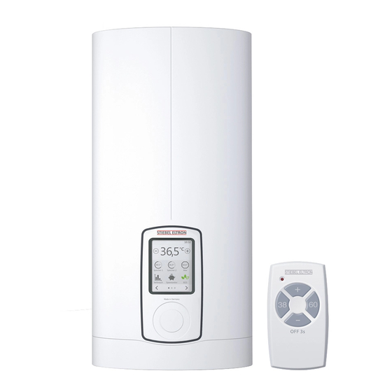
Vollelektronisch geregelter Komfort-Durchlauferhitzer mit Mini-Funk-Fernbedienung | Fully
electronically controlled comfort instantaneous water heater with mini wireless remote
control | Chauffe-eau instantané confort à régulation entièrement électronique avec
mini commande à distance radio | Geheel elektronisch geregelde Comfort-doorstromer
met draadloze miniafstandsbediening | Całkowicie elektronicznie regulowany komfortowy
przepływowy ogrzewacz wody z miniaturowym radiowym pilotem zdalnego sterowania |
Plně elektronicky regulovaný komfortní průtokový ohřívač vody s rádiovým dálkovým
miniovladačem | Plne elektronicky regulovaný komfortný prietokový ohrievač s mini
rádiovým diaľkovým ovládaním
» DHE Connect 18/21/24
» DHE Connect 27
» DHE Touch 18/21/24
» DHE Touch 27
Advertisement
Chapters
Table of Contents
Troubleshooting

Related Manuals for STIEBEL ELTRON DHE Connect 18/21/24


Summary of Contents for STIEBEL ELTRON DHE Connect 18/21/24
- Page 1 BEDIENUNG UND INSTALLATION OPERATION AND INSTALLATION UTILISATION ET INSTALLATION BEDIENING EN INSTALLATIE OBSŁUGA I INSTALACJA OBSLUHA A INSTALACE OBSLUHA A INŠTALÁCIA Vollelektronisch geregelter Komfort-Durchlauferhitzer mit Mini-Funk-Fernbedienung | Fully electronically controlled comfort instantaneous water heater with mini wireless remote control | Chauffe-eau instantané confort à régulation entièrement électronique avec mini commande à...
-
Page 2: Table Of Contents
INHALT BESONDERE HINWEISE Technische Daten ������������������������������������������� 48 BEDIENUNG KUNDENDIENST UND GARANTIE Allgemeine Hinweise ����������������������������������������4 UMWELT UND RECYCLING Sicherheit �����������������������������������������������������6 SOFTWARE URHEBERECHT Gerätebeschreibung �����������������������������������������7 Einstellungen �������������������������������������������������9 Reinigung, Pflege und Wartung �������������������������� 19 GARANTIEVERLÄNGERUNG Problembehebung ����������������������������������������� 20 › Garantieverlängerung ������������������������������������� 23 Produkt registrieren ›... -
Page 3: Besondere Hinweise
Besondere Hinweise Besondere Hinweise - Das Gerät ist für die Versorgung einer Dusche (Duschbetrieb) geeignet. Wenn das Gerät auch oder ausschließlich für den Duschbetrieb - Das Gerät kann von Kindern ab 3 Jahren sowie genutzt wird, muss der Fachhandwerker den von Personen mit verringerten physischen, Temperatureinstellbereich über den internen sensorischen oder mentalen Fähigkeiten oder Verbrühschutz im Gerät auf 55 °C oder gerin-... -
Page 4: Bedienung
Bedienung Allgemeine Hinweise Bedienung - Befestigen Sie das Gerät wie in Kapitel „Ins- tallation / Montage“ beschrieben. - Beachten Sie den maximal zulässigen Druck Allgemeine Hinweise (siehe Kapitel „Installation / Technische Daten / Datentabelle“). Die Kapitel „Besondere Hinweise“ und „Bedienung“ richten sich an den Gerätebenutzer und den Fachhandwerker. - Der spezifische Wasserwiderstand des Was- Das Kapitel „Installation“... - Page 5 Bedienung Allgemeine Hinweise 1.1.2 Symbole, Art der Gefahr Andere Markierungen in dieser Dokumentation Symbol Art der Gefahr Verletzung Hinweis Allgemeine Hinweise werden mit dem nebenstehenden Symbol gekennzeichnet. Stromschlag f Lesen Sie die Hinweistexte sorgfältig durch. Verbrennung Symbol Bedeutung (Verbrennung, Verbrühung) Sachschaden (Geräte-, Folge-, Umweltschaden) Geräteentsorgung 1.1.3 Signalworte SIGNALWORT...
-
Page 6: Sicherheit
Bedienung Sicherheit Sicherheit Allgemeine Sicherheitshinweise VORSICHT Verbrennung Bestimmungsgemäße Verwendung Die Armatur kann eine Temperatur von über 70 °C an- Das Gerät dient zur Erwärmung von Trinkwasser oder zur Nacher- nehmen. Bei Auslauftemperaturen größer 43 °C besteht wärmung von vorgewärmtem Wasser. Das Gerät kann eine oder Verbrühungsgefahr. -
Page 7: Gerätebeschreibung
Bedienung Gerätebeschreibung Gerätebeschreibung - vom Benutzer einstellbar: „MAX“ Temperaturbegrenzung / Kindersicherung, Sobald Sie das Warmwasserventil an der Armatur öffnen, schaltet - vom Fachhandwerker einstellbar: „Interner Verbrühschutz“. sich das Gerät automatisch ein. Wenn Sie die Armatur schließen schaltet sich das Gerät automatisch wieder aus. Sachschaden Das Gerät erwärmt das Wasser, während es durch das Gerät Das Gerät und die Armatur sind vom Nutzer vor Frost zu... - Page 8 Bedienung Gerätebeschreibung Betätigung ab (Abschaltzeit vom Benutzer veränderbar). Sobald Hinweis Wasser durch das Gerät fließt oder Sie eine Veränderung an der Das Gerät ist mit einer Lufterkennung ausgestattet, die Bedieneinheit oder an der Mini-Funk-Fernbedienung vornehmen eine Beschädigung des Heizsystems weitgehend verhin- wird die Hintergrundbeleuchtung automatisch eingeschaltet.
-
Page 9: Einstellungen
Bedienung Einstellungen Aufbau der Bedieneinheit Einstellungen Temperatureinstellungen Speicher 1 Speicher 2 Maximum Wetter Radio OFF 3s 1 Touch-Screen 2 Touch-Wheel, wählbare Funktionen: „Temperatur, Lautstärke (nur „DHE Connect“) und „Keine Funktion“ 1 Tasten „-“ und „+“, schnelle Veränderung bei anhaltender 3 Lautsprecher (nur „DHE Connect“) Betätigung Der Touch-Screen reagiert auf punktuelle Berührung (kein „Wi- 2 Schnellwahl der Temperatur über die Speichertasten... - Page 10 Bedienung Einstellungen Dynamischer Verbrühschutz 4 Aktivierte Symbole schwarz hinterlegt: „Maximum, ECO, Wannenfüllung und Wellness“ Mit dem dynamischen Verbrühschutz erhält der Benutzer, der zu- 5 Navigation (zum Wechseln der Seiten) erst eine Temperatur am Gerät oder Funk-Fernbedienung wählt, Symbol Bedeutung automatisch Priorität für die Einstellung der Maximaltemperatur. zurück zum Startbildschirm Die Priorität besteht für 2 Minuten oder bis 2 Minuten nach Ende der aktuellen Entnahme.
- Page 11 Bedienung Einstellungen Wetter Radio nur „DHE Connect“ mit WLAN-Verbindung und erfolgter Regis- nur „DHE Connect“ mit WLAN-Verbindung und erfolgter Regis- trierung trierung 9/12/15 Holzminden 1 Start / Pause 1 Aktuelle Wetterdaten 2 Nächster Sender 2 3-Tage Wetter Vorhersage 3 Lautstärke 3 Ort hinzufügen (weltweit, die Wetterdaten stammen von 4 ender hinzufügen / abwählen, weltweite Suchfunktion (Radio Q.met „qmet.de“) Funktion basiert auf der Datenbank von „radio.de“)
- Page 12 Die Bluetooth -Wortmarke und -Logos sind eingetragene Mar- ken der Bluetooth SIG, Inc., und jeder Gebrauch dieser Marken durch STIEBEL ELTRON erfolgt unter Lizenz. Andere Marken und Handelsnamen sind Eigentum der jeweiligen Rechteinhaber. Aktivieren / Deaktivieren der gewählten maximalen Durchfluss- menge (siehe Menü „Einstellungen“) Jede Aktivierung der ECO-Funktion wird für die Berechnung des...
- Page 13 Bedienung Einstellungen Verbrauch Wellness-Duschprogramme In den Anzeigen können Sie den Strom- und Wasserverbrauch, Die Warm- und Kaltwassertemperaturen lassen sich über das die Dauer und die Kosten ablesen. Touch-Wheel verändern (nur bei Aktivierung „Temperatur“ im Touch-Wheel). Ihre Verbrauchsdaten werden alle 15 Minuten gespeichert. Wenn Einstellung Beschreibung die Stromversorgung unterbrochen wird, sind die Verbrauchsda-...
- Page 14 Bedienung Einstellungen Dusch-Timer Zahnputz-Timer f Tippen Sie 1x auf den Kreis. Anschließend wählen Sie die f Tippen Sie 1x auf den Kreis. Anschließend wählen Sie die Dauer, indem Sie „05:00 min“ drücken und die gewünschte Dauer, indem Sie „03:00 min“ drücken und die gewünschte Dauer einstellen.
- Page 15 Bedienung Einstellungen Menüstruktur Beschreibung … Touch-Wheel Temperatur, Lautstärke (nur bei „DHE Connect“ wählbar), keine Funktion … Icon Größe Display Ansicht wählen. … Funktionen aktivieren Funktionen für den Startbildschirm. … Funktionen sortieren Reihenfolge der Funktionen auf dem Startbildschirm. …...
- Page 16 Bedienung Einstellungen Menüstruktur Beschreibung „ Info Informationen zum Gerät abfragen … Gerätedaten Gerätedaten-Anzeige … Versionsinfo Versionsanzeige; Update-Prüfung bei DHE Connect mit WLAN-Verbindung möglich. Vorhandene Soft- ware-Aktualisierungen nacheinander installieren. Hinweis: Trennen Sie das Gerät während der Software-Aktualisierung nicht von der Spannungsversor- gung.
- Page 17 Bedienung Einstellungen Menüstruktur Beschreibung … … Weiteren Funkteilnehmer anmelden Starten des Funkeinrichtmodus im Durchlauferhitzer über die Bedieneinheit, zur Einrichtung der Funkverbindung zu einer externen Bedieneinheit oder einer Funk-Fernbedienung. … Fehler Anzeige von Gerätefehlern. … Fachhandwerker-Kontakt Der Fachhandwerker kann hier für den Servicefall seine Kontaktdaten hinterlegen. …...
- Page 18 Bedienung Einstellungen Neue Mini-Funk-Fernbedienung einlernen Wenn die Batterie leer ist, beachten Sie das Kapitel „Problembe- hebung / Batterietausch der Mini-Funk-Fernbedienung“. Die Mini-Funk-Fernbedienung lernen Sie wie folgt ein: f Öffnen Sie an der im Durchlauferhitzer eingebauten Bedien- Neue / zusätzliche Bedieneinheiten einlernen einheit den Menüpunkt „Service / Funk / Weiteren Funkteil- Mit der DHE Bedieneinheit können Sie das Gerät per Funk bedie- nehmer anmelden“.
-
Page 19: Reinigung, Pflege Und Wartung
Bedienung Reinigung, Pflege und Wartung Interner Verbrühschutz (Fachandwerker) App-Bedienung Auf Wunsch kann der Fachhandwerker eine dauerhafte Tempera- Die App-Bedienung ist für die Steuerung des „DHE Connect“ vor- turbegrenzung einstellen, z. B. in Kindergärten, Krankenhäusern gesehen. Sie können das Gerät unter folgenden Voraussetzungen usw. mit einem mobilen Endgerät bedienen: Bei Versorgung einer Dusche muss der Fachhandwerker den Tem- - Software-Version der Bedieneinheit mindestens 1.9.00., siehe peratureinstellbereich im Gerät auf 55 °C oder geringer begrenzen. -
Page 20: Problembehebung
Bedienung Problembehebung f Kontrollieren Sie regelmäßig die Armaturen. Kalk an den Armaturausläufen können Sie mit handelsüblichen Entkal- kungsmitteln entfernen. Problembehebung Problem Ursache Behebung Das Gerät schaltet trotz voll geöffnetem Es liegt keine Spannung an. Prüfen Sie die Sicherungen in der Hausinstallation. Warmwasser-Ventil nicht ein. - Page 21 Aus- und Ein- wachungs- und Reparaturmodus, welcher die Benutzereinstellungen neu vornehmen. schalten der Sicherungen neu gestartet. bei Fehlern in der Bedieneinheit automatisch Anstelle des STIEBEL ELTRON - Logos durchgeführt wird. erscheinen Systemmeldungen auf dem Touch-Display. Die Temperatur lässt sich am Touch- Die Funktion „Temperatur“...
- Page 22 Bedienung Problembehebung Problem nur „DHE Connect“ Ursache Behebung Fehler beim WLAN einrichten. Die IP-Adresse konnte nicht bezogen werden. Überprüfen Sie die Einstellungen im Router und ihre Internetverbindung. Der Router hat sich bei der WLAN-Einrich- Wiederholen Sie die WLAN-Einrichtung. tung ausgeschaltet (Timeout). Der WLAN-Empfang ist zu schwach. Prüfen Sie, ob ihr WLAN am Installationsort stabil verfügbar ist.
-
Page 23: Garantieverlängerung
Nach erfolgter Registrierung innerhalb der Garantie verlängert sich diese für Ihren DHE Connect oder Touch um weitere 12 Monate gemäß den Garantiebedingungen der Hinweis STIEBEL ELTRON GmbH & Co. KG. Der Pluspol der Batterie muss von der Platine abgewandt sein. SCHNELLE HILFE f Verschließen Sie das Gehäuse. -
Page 24: Installation
INSTALLATION Sicherheit INSTALLATION Duschbetrieb VORSICHT Verbrennung f Stellen Sie bei Versorgung einer Dusche den inter- nen Verbrühschutz auf 55 °C oder geringer ein. Sicherheit Die Installation, Inbetriebnahme sowie Wartung und Reparatur VORSICHT Verbrennung des Gerätes darf nur von einem Fachhandwerker durchgeführt Bei Versorgung des Gerätes mit vorgewärmtem Wasser werden. -
Page 25: Gerätebeschreibung
INSTALLATION Gerätebeschreibung Mini-Funk-Fernbedienung - Der spezifische elektrische Widerstand des Wassers darf nicht kleiner sein als auf dem Typenschild angegeben. - Sender inkl. Batterie Bei einem Wasser-Verbundnetz berücksichtigen Sie den - Wandhalterung und Klebepad niedrigsten elektrischen Widerstand des Wassers. Den spezifischen elektrischen Widerstand oder die elektri- Zubehör sche Leitfähigkeit des Wassers erfahren Sie bei Ihrem Wasserversorgungs-Unternehmen. -
Page 26: Vorbereitungen
INSTALLATION Vorbereitungen Universal-Montagerahmen Zentral-Thermostat-Armatur (ZTA 3/4) - Montagerahmen mit elektrischen Anschlüssen Die Thermostat-Armatur für zentrale Vormischung verwenden Sie z. B. bei Betrieb eines Durchlauferhitzers mit vorgewärmtem Rohrbausatz-Untertischgeräte Wasser. Für den Einsatz im Duschbetrieb ist die Einstellung der Armatur auf max. 55 °C vorzunehmen. Wenn Sie die Wasseranschlüsse (G ⅜ A) oberhalb des Gerätes an- schließen, benötigen Sie den Bausatz für die Untertischmontage. - Page 27 INSTALLATION Vorbereitungen Untertischmontage Hinweis f Montieren Sie das Gerät an der Wand. Die Wand muss ausreichend tragfähig sein. 10.2 Mindestabstände 1 Kaltwasser Zulauf 2 Warmwasser Auslauf ≥50 ≥50 Übertischmontage f Halten Sie die Mindestabstände ein, um einen störungsfreien Betrieb des Gerätes zu gewährleisten und Wartungsarbeiten am Gerät zu ermöglichen.
-
Page 28: Montage
INSTALLATION Montage 10.3 Wasserinstallation Volumenstrom f Stellen Sie sicher, dass der Volumenstrom zum Einschalten f Spülen Sie die Wasserleitung gut durch. des Gerätes erreicht wird. Armaturen f Falls der benötigte Volumenstrom bei voll geöffnetem Entnahmeventil nicht erreicht wird, erhöhen Sie den Verwenden Sie geeignete Druckarmaturen. -
Page 29: Standardmontage
INSTALLATION Standardmontage Standardmontage Netzanschlusskabel vorbereiten Gerät öffnen 1 Montagehilfe zur Kabeleinführung f Bereiten Sie das Netzanschlusskabel vor. Wandaufhängung montieren f Öffnen Sie das Gerät, indem Sie die Blende seitlich anfassen und von der Gerätekappe nach vorn abziehen. Lösen Sie die Schraube. - Page 30 INSTALLATION Standardmontage Doppelnippel montieren 4 Sieb 5 Kunststoff-Formscheibe Sachschaden f Schrauben Sie das T-Stück und das 3-Wege-Kugelabsperr- Führen Sie alle Wasseranschluss- und Installationsarbei- ventil mit jeweils einer Flachdichtung auf die Doppelnippel. ten nach Vorschrift aus. Sachschaden Für die Funktion des Gerätes muss das Sieb eingebaut sein.
- Page 31 INSTALLATION Standardmontage f Führen Sie das Netzanschlusskabel mit der Kabeltülle von 1 Montagehilfe zur Kabeleinführung 2 Kabeltülle hinten durch die Rückwand. f Montieren Sie das Gerät auf den Gewindebolzen der Verwenden Sie zur besseren Durchgängigkeit der Adern durch die Wandaufhängung. Kabeltülle die Montagehilfe (siehe beigelegtes Kunststoff-Teileset).
- Page 32 INSTALLATION Standardmontage Elektroanschluss herstellen Rückwand-Unterteil montieren WARNUNG Stromschlag Führen Sie alle elektrischen Anschluss- und Installati- onsarbeiten nach Vorschrift aus. WARNUNG Stromschlag Der Anschluss an das Stromnetz ist nur als fester An- schluss in Verbindung mit der herausnehmbaren Kabel- tülle erlaubt. Das Gerät muss über eine Trennstrecke von f Montieren Sie das Rückwand-Unterteil in die Rückwand.
-
Page 33: Inbetriebnahme
INSTALLATION Inbetriebnahme 12.1 Montage Mini-Funk-Fernbedienung f Aktivieren Sie den Sicherheitsschalter, indem Sie die Rück- setztaste fest eindrücken (das Gerät wird mit deaktiviertem Sie können die Mini-Funk-Fernbedienung mithilfe der Wandhal- Sicherheitsschalter ausgeliefert). terung an der Wand befestigen. Bei den Geräten „DHE Connect 18/21/24“ und „DHE Touch 18/21/24“ f Befestigen Sie die Wandhalterung mit dem beiliegenden ist die mittlere Anschlussleistung (21 kW) werkseitig voreinge- Klebepad oder einer geeigneten Senkkopfschraube (∅ 3 mm... - Page 34 INSTALLATION Inbetriebnahme f Kreuzen Sie die gewählte Anschlussleistung und die 13.1.1 Anschlussleistung umstellen: „DHE Connect 18/21/24“ und „DHE Touch 18/21/24“ Nennspannung auf dem Typenschild der Gerätekap- pe (auf beiden Seiten) an. Verwenden Sie dafür einen Wenn Sie bei den Geräten mit umschaltbarer Anschlussleistung Kugelschreiber. eine andere Anschlussleistung als die 21 kW Werkseinstellung f Befestigen Sie die Gerätekappe mit der Schraube.
-
Page 35: Außerbetriebnahme
INSTALLATION Außerbetriebnahme 13.1.2 Mini-Funk-Fernbedienung 13.2 Wiederinbetriebnahme Die Mini-Funk-Fernbedienung ist werkseitig am Gerät angemel- Sachschaden det. Wenn bei der Inbetriebnahme keine Datenübertragung er- Damit das Blankdraht-Heizsystem nach Unterbrechung folgt, führen Sie den Einlernvorgang erneut durch (siehe Kapitel der Wasserversorgung nicht zerstört wird, muss das „Montage-Alternativen / Anmeldung der Mini-Funk-Fernbedie- Gerät mit folgenden Schritten wieder in Betrieb genom- nung“. -
Page 36: Montage-Alternativen
INSTALLATION Montage-Alternativen 15. Montage-Alternativen Das Gerät verfügt über eine Verbrühschutzfunktion, die der Fach- handwerker auf Wunsch einstellen kann. Dazu muss das Gerät Elektroanschluss Schutzart (IP) geöffnet werden. Unterputz oben IP 25 Verbrühschutz aktivieren Unterputz unten bei kurzem Netzanschlusskabel IP 25 Aufputz IP 24 f Drücken Sie die Taste „Service“ auf der Elektronik im Gerät. Wasseranschluss Schutzart (IP) Aufputz... - Page 37 INSTALLATION Montage-Alternativen f Versetzen Sie die Netzanschlussklemme von unten nach VORSICHT Verbrennung oben. Lösen Sie dazu die Befestigungsschraube. Drehen Sie Bei Versorgung des Gerätes mit vorgewärmtem Wasser die Netzanschlussklemme mit den Anschlusskabeln 180° im können der interne Verbrühschutz und die vom Benut- Uhrzeigersinn.
- Page 38 INSTALLATION Montage-Alternativen 15.3 Elektroanschluss Unterputz unten bei kurzem Netzanschlusskabel 1 Kabeltülle f Bereiten Sie das Netzanschlusskabel vor. Montieren Sie die Kabeltülle. Sachschaden Haben Sie versehentlich ein falsches Loch in die Rück- wand oder Gerätekappe gebrochen, müssen Sie neue Bauteile Rückwand oder Gerätekappe verwenden. f Versetzen Sie die Netzanschlussklemme weiter nach unten.
- Page 39 INSTALLATION Montage-Alternativen 15.5 Anschluss eines Lastabwurfrelais Setzen Sie ein Lastabwurfrelais in Kombination mit anderen 5 Nm Elektrogeräten, z. B. Elektro-Speicherheizgeräte, in der Elektro- verteilung ein. Der Lastabwurf erfolgt bei Betrieb des Durchlauf- 18 Nm erhitzers. Sachschaden Schließen Sie die Phase, die das Lastabwurfrelais schal- tet, an die gekennzeichnete Klemme der Netzanschluss- f Montieren Sie Wasserstopfen mit Dichtungen, um den Unter- klemme im Gerät an (siehe Kapitel „Technische Daten /...
- Page 40 INSTALLATION Montage-Alternativen 15.8 Montage der Gerätekappe bei Wasserinstallation Aufputz 1 Lasche 15.7 Wasserinstallation Aufputz mit Lötanschluss / Press-Fitting Mit dem Zubehör „Lötanschluss“ oder „Press-Fitting“ können Sie Kupfer-Rohrleitungen oder auch Kunststoff-Rohrleitungen ver- binden. 1 Rückwand-Führungsstücke Beim „Lötanschluss“ mit einem Schraubanschluss für 12 mm Kup- 2 Schraube fer-Rohrleitungen müssen Sie wie folgt vorgehen: 3 Kappen-Führungsstücke mit rohrseitigen Dichtlippen...
- Page 41 INSTALLATION Montage-Alternativen f Stecken Sie die Verbindungsstücke von hinten in das Rück- Hinweis wand-Unterteil ein. Sie können bei einem leichten Versatz der Anschlussrohre f Rasten Sie das Rückwand-Unterteil in die Rückwand ein. die Kappen-Führungsstücke mit Dichtlippen verwenden. f Befestigen Sie das Rückwand-Unterteil mit einer Schraube. In diesem Fall werden die Rückwand-Führungsstücke nicht montiert.
- Page 42 INSTALLATION Montage-Alternativen 15.11 Installation bei Fliesenversatz 15.12 Gedrehte Gerätekappe Bei einer Untertischmontage kann die Gerätekappe gedreht wer- den. 1 Mindestauflage des Gerätes 2 Maximaler Fliesenversatz f Justieren Sie den Wandabstand. Verriegeln Sie die Rückwand mit dem Befestigungsknebel (90° Rechtsdrehung). f Demontieren Sie die Bedieneinheit aus der Gerätekappe, indem Sie die Rasthaken drücken und die Bedieneinheit herausnehmen.
- Page 43 INSTALLATION Montage-Alternativen 15.14 Anmelden der Mini-Funk-Fernbedienung WARNUNG Stromschlag Die Bedieneinheit muss mit allen 4 Rasthaken eingerastet Die Mini-Funk-Fernbedienung kann, wie im Kapitel „Einstellun- werden. Die Rasthaken müssen vollständig und unbe- gen / Service / Funk / Weiteren Funkteilnehmer anmelden“ be- schädigt sein. Bei einer nicht korrekt eingesetzten Be- schrieben, über die Bedieneinheit eingelernt werden.
-
Page 44: Service-Informationen
INSTALLATION Service-Informationen 15.15 DHE Bedieneinheit als Funk-Fernbedienung 1 Taster vom Funkmodul zum Anmelden 2 Gelbe LED-Anzeige bei aktivierter Bedieneinheit anmelden f Aktivieren Sie an der Bedieneinheit den Menüpunkt „Einstel- Wird die Bedieneinheit mit Zubehör außerhalb des Gerätes ein- lungen / Service / Funk / Bedienteil anmelden“. gesetzt und das Gerät ist durch die Blindkappe verschlossen, so f Drücken Sie im Gerät kurz auf den Taster des Funkmoduls. - Page 45 INSTALLATION Service-Informationen Menüstruktur Beschreibung … Service-Code Mit der Eingabe des Service-Codes werden die Menüpunkte „Kontrollmenü“ und „Netzwerkdiagnose“ ange- zeigt. ► Geben Sie den Service-Code „1000“ ein. ► Aktivieren Sie den Service-Code mit dem Hakensymbol (auf dem Display erscheint „Servicelevel 1“), wei- ter mit dem Pfeilsymbol.
-
Page 46: Störungsbehebung
INSTALLATION Störungsbehebung Gerätekappenhalterung 17. Störungsbehebung WARNUNG Stromschlag Um das Gerät prüfen zu können, muss die Netzspannung am Gerät anliegen. Hinweis Die Anzeige der Diagnoseampel erfolgt bei fließendem Wasser. Anzeigemöglichkeiten der Diagnoseampel (LED) leuchtet bei Störung gelb leuchtet bei Heizbetrieb / blinkt bei Erreichen der Leistungsgrenze grün blinkt: Gerät am Netzanschluss Diagnoseampel... - Page 47 INSTALLATION Störungsbehebung Diagnoseampel Störung Ursache Behebung Das Verbindungskabel der Bedieneinheit ist defekt. Prüfen Sie das Verbindungskabel, tauschen Sie es ggf. aus. Die Elektronik der Bedieneinheit ist defekt. Prüfen Sie die Bedieneinheit, tauschen Sie sie ggf. aus. Grün blinkt, gelb ein, Kein Warmwasser, die Aus- Die nachgeschaltete Armatur ist defekt.
-
Page 48: 18. Wartung
INSTALLATION Wartung 18. Wartung 19. Technische Daten 19.1 Maße und Anschlüsse WARNUNG Stromschlag Trennen Sie bei allen Arbeiten das Gerät allpolig vom ≤ 20 Netzanschluss. Gerät entleeren Das Gerät können Sie für Wartungsarbeiten entleeren. WARNUNG Verbrennung Wenn Sie das Gerät entleeren, kann heißes Wasser aus- treten. - Page 49 INSTALLATION Technische Daten Alternative Anschlussmöglichkeiten Mini-Funk-Fernbedienung OFF 3s b02 Durchführung elektr. Leitungen I Unterputz b03 Durchführung elektr. Leitungen II Unterputz b04 Durchführung elektr. Leitungen III Aufputz www.stiebel-eltron.com DHE Connect | DHE Touch | ...
- Page 50 INSTALLATION Technische Daten 19.2 Elektroschaltplan Vorrangschaltung mit LR 1-A 3/PE ~ 380-415 V 1 Steuerleitung zum Schaltschütz des 2. Gerätes (z. B. Elektro-Speicherheizgerät) 2 Steuerkontakt öffnet beim Einschalten des Durchlauferhitzers. 1 Leistungselektronik mit integriertem Sicherheitsschalter 2 Blankdraht-Heizsystem 3 Sicherheitstemperaturbegrenzer 4 Netzanschlussklemme 50 |DHE Connect | DHE Touch www.stiebel-eltron.com...
- Page 51 INSTALLATION Technische Daten 19.3 Warmwasser-Leistung Anschlussleistung in kW 50 °C Warmwasser-Leistung in l/min. Die Warmwasser-Leistung ist abhängig von der anliegenden Netz- Nennspannung Kaltwasser-Zulauftemperatur spannung, der Anschlussleistung des Gerätes und der Kaltwas- 380 V 400 V 415 V 5 °C 10 °C 15 °C 20 °C ser-Zulauftemperatur. Die Nennspannung und die Nennleistung 16,2 entnehmen Sie dem Typenschild.
- Page 52 INSTALLATION Technische Daten 19.5 Druckverluste 19.8 Landesspezifische Zulassungen und Zeugnisse: Deutschland Armaturen Für das Gerät ist aufgrund der Landesbauordnungen ein allgemei- Druckverlust der Armaturen bei Volumenstrom 10 l/min nes bauaufsichtliches Prüfzeugnis zum Nachweis der Verwend- Einhandmischer, ca. 0,04 - 0,08 barkeit hinsichtlich des Geräuschverhaltens erteilt. Thermostat-Armatur, ca. 0,03 - 0,05 Duschkopf, ca.
- Page 53 19.9 Angaben zum Energieverbrauch Produktdatenblatt: Konventionelle Warmwasserbereiter nach Verordnung (EU) Nr. 812/2013 und 814/2013 DHE Connect 18/21/24 DHE Connect 27 DHE Touch 18/21/24 DHE Touch 27 234467 234468 234459 234460 Hersteller STIEBEL ELTRON STIEBEL ELTRON STIEBEL ELTRON STIEBEL ELTRON Lastprofil Energieeffizienzklasse Energetischer Wirkungsgrad Jährlicher Stromverbrauch Temperatureinstellung ab Werk °C Schallleistungspegel...
- Page 54 INSTALLATION Technische Daten DHE Connect 18/21/24 DHE Connect 27 DHE Touch 18/21/24 DHE Touch 27 Max. Netzimpedanz bei 50Hz Ω 0,284 0,270 0,260 0,254 0,241 0,284 0,270 0,260 0,254 0,241 Spezifischer Widerstand ρ15 ≥ Ω cm Spezifische Leitfähigkeit σ15 ≤ μS/cm 1111 1111 1111 1111 Anschlüsse Wasseranschluss G 1/2 A G 1/2 A G 1/2 A G 1/2 A...
- Page 55 INSTALLATION Technische Daten DHE Connect 18/21/24 DHE Connect 27 DHE Touch 18/21/24 DHE Touch 27 Breite Tiefe Gewichte Gewicht Die Funkreichweite ist abhängig von den baulichen Gegebenhei- Hinweis ten. Eine Funktion durch eine Geschossdecke kann nicht immer Das Gerät stimmt mit IEC 61000-3-12 überein. garantiert werden. Mini-FFB Einsatzgrenzen Temperatureinstellbereich °C 20-60 Sendefrequenz...
- Page 56 Rufen Sie uns an: 05531 702-111 Inhalt und Umfang der Garantie oder schreiben Sie uns: Stiebel Eltron GmbH & Co. KG Die Garantieleistung wird erbracht, wenn an unseren Geräten ein - Kundendienst - Herstellungs- und/oder Materialfehler innerhalb der Garantiedauer Fürstenberger Straße 77, 37603 Holzminden auftritt.
- Page 57 KUNDENDIENST UND GARANTIE Für die Dauer und Reichweite der Garantie übernehmen wir sämtli- tiedauer in Gang gesetzt. Dies gilt für alle erbrachten Garantieleis- che Material- und Montagekosten. tungen, insbesondere für etwaig eingebaute Ersatzteile oder für die Ersatzlieferung eines neuen Gerätes. Soweit der Kunde wegen des Garantiefalles aufgrund gesetzlicher Gewährleistungsansprüche gegen andere Vertragspartner Leistun- Inanspruchnahme der Garantie...
- Page 58 UMWELT UND RECYCLING Entsorgung von Transport- und Über das Rücknahmesystem werden hohe Recyclingquoten der Ma- Verkaufsverpackungsmaterial terialien erreicht, um Deponien und die Umwelt zu entlasten. Damit leisten wir gemeinsam einen wichtigen Beitrag zum Umweltschutz. Damit Ihr Gerät unbeschädigt bei Ihnen ankommt, haben wir es sorgfältig verpackt.
- Page 59 Besitzer des Gerätes und jeden, der diese Information besitzt. Ansprechpartner für den Erhalt des Quellcodes ist der Stiebel Eltron-Kundenservice (Stiebel Eltron GmbH & Co. KG, – Kundenservice-, Dr. Stiebel-Str. 33, 37603 Holzminden). Weitere Details können Sie der vorgenannten Website entnehmen.
- Page 60 CONTENTS | SPECIAL INFORMATION SPECIAL INFORMATION GUARANTEE OPERATION ENVIRONMENT AND RECYCLING General information ��������������������������������������� 62 SOFTWARE COPYRIGHT Safety �������������������������������������������������������� 63 Appliance description ������������������������������������� 64 Settings ����������������������������������������������������� 66 Cleaning, care and maintenance ������������������������� 76 Troubleshooting �������������������������������������������� 76 INSTALLATION SPECIAL INFORMATION Safety �������������������������������������������������������� 80 Appliance description ������������������������������������� 81 Preparation �������������������������������������������������...
-
Page 61: Special Information
SPECIAL INFORMATION - The tap can reach temperatures in excess of - The appliance must be permanently connect- 70 °C. There is a risk of scalding at outlet tem- ed to fixed wiring. peratures in excess of 43 °C. - Secure the appliance as described in chapter - The appliance is suitable for supplying a "Installation / Installation". -
Page 62: General Information
OPERATION General information OPERATION 1.1.2 Symbols, type of risk Symbol Type of risk Injury General information Electrocution The chapters "Special information" and "Operation" are intended for both users and qualified contractors. Burns (burns, scalding) The chapter "Installation" is intended for qualified contractors. Note 1.1.3 Keywords Read these instructions carefully before using the appli- KEYWORD... -
Page 63: Safety
OPERATION Safety Water will not be reheated if the maximum inlet temperature for Symbol Meaning reheating is exceeded. Material losses (appliance damage, consequential losses and environmen- The appliance is intended for domestic use. It can be used safely tal pollution) by untrained persons. -
Page 64: Appliance Description
OPERATION Appliance description WARNING Injury Note The appliance may be used by children aged 3 and older The mini wireless remote control has a lithium button and persons with reduced physical, sensory or mental cell as battery for the power supply. capabilities or a lack of experience and know-how, pro- Remove spent batteries. - Page 65 OPERATION Appliance description If the appliance is operated with preheated water and the inlet susceptible to scale build-up. The heating system ensures rapid temperature exceeds the chosen set temperature, a warning mes- and efficient DHW provision. sage appears on the display. The water is not heated further. Note You can save and quickly call up different temperatures.
-
Page 66: Settings
OPERATION Settings Programming unit layout Settings Temperature settings Memory 1 Memory 2 Maximum Weather Radio OFF 3s 1 Touchscreen 2 Touch wheel, selectable functions: "Temperature", "Volume" (DHE Connect only) and "No function" 1 Buttons "-" and "+"; press and hold to go faster 3 Loudspeaker (DHE Connect only) 2 Rapid selection of temperature with the memory buttons The touchscreen responds to being tapped (not "swiping"). - Page 67 OPERATION Settings Dynamic anti-scalding protection 5 Navigation (to scroll through pages) Symbol Meaning With the dynamic anti-scalding protection, after selecting a tem- Back to start screen perature on the appliance or wireless remote control, the user has automatic priority for setting the maximum temperature. The Navigate priority is active for 2 minutes or until 2 minutes after the current draw-off ends.
- Page 68 OPERATION Settings Weather Radio DHE Connect with WLAN connection and prior registration only DHE Connect with WLAN connection and prior registration only 9/12/15 Holzminden 1 Start/pause 1 Latest weather information 2 Next station 2 3-day weather forecast 3 Volume 3 Add location (worldwide, weather data originates from 4 Add/remove station, global search function (radio function Q.met "qmet.de") based on the "radio.de"...
- Page 69 The Bluetooth word mark and logos are registered trademarks of Bluetooth SIG, Inc. and are always used by STIEBEL ELTRON The Bluetooth® loudspeaker can be paired in the "Settings" menu under licence. Other trademarks and brand names are the prop- as follows: erty of the respective copyright holder.
- Page 70 OPERATION Settings Example: "Cold prevention" Bath filling f Select a "Warm" temperature. Enabling/disabling automatic bath filling Starting at the selected hot water temperature, the water temper- When activated, flow rates are reduced once the set amount has ature is reduced to the cold water temperature. been reached.
- Page 71 OPERATION Settings Settings You can make individual settings for currency, temperature (Cel- Conversion factor: sius °C/Fahrenheit °F) and volume (litres/gallons). 1 litre = 0.26417 gal. (3.78541 litres = 1 gal.) Menu structure Description „ Temperature memory Store up to 12 names and temperatures. … ...
- Page 72 OPERATION Settings Menu structure Description … Units and values … … Time For DHE Touch and DHE Connect with no WLAN connection. … … Date For DHE Touch and DHE Connect with no WLAN connection. … … Units and values Values for "Consumption" and "Economy monitor" calculation. …...
- Page 73 OPERATION Settings Menu structure Description … WLAN Visible WLAN transmitters are detected automatically (can take up to 1 minute). Make sure that your router/repeater settings allow additional WLAN subscribers. Use the "WPS" (Wi-Fi Protected Setup) button for easy wireless home network registration. Alterna- tively you can input the key manually, or connect to a hidden WLAN network by entering the SSID and key.
- Page 74 OPERATION Settings Mini wireless remote control f Press a button on the mini wireless remote control. This transmits data to the appliance. The red LED confirms Using the mini wireless remote control you can adjust the temper- that the button information has been transmitted to the ature setting wirelessly.
- Page 75 OPERATION Settings Pairing a new mini wireless remote control Internal anti-scalding protection (qualified contractors) If required, the qualified contractor can set a permanent temper- You pair the mini wireless remote control as follows: ature limit, for example in nurseries, hospitals, etc. f Using the programming unit built into the instantaneous water heater, open the "Service / Wireless / Connect other When supplying a shower, the appliance temperature setting...
-
Page 76: Cleaning, Care And Maintenance
OPERATION Cleaning, care and maintenance - To use this function, you must install the DHE Connect app. App-based operation Here, you will also find further information about the app. App-based operation is intended for controlling the DHE Connect. You can use a mobile terminal device to operate the appliance Cleaning, care and maintenance under the following conditions: f Never use abrasive or corrosive cleaning agents. - Page 77 System mes- matically in the event of programming unit sages appear on the touchscreen in place errors. of the STIEBEL ELTRON logo. The temperature cannot be adjusted with The "Temperature" function has not been set Set the function for temperature.
- Page 78 OPERATION Troubleshooting Problems specific to DHE Con- Cause Remedy nect The radio is regularly interrupted. The WLAN reception is too weak. Check the signal strength in the status bar. Use a repeater to improve sig- nal strength if necessary. The internet access bandwidth is too low. Contact your internet provider to find out whether access with increased bandwidth is available.
- Page 79 OPERATION Troubleshooting Problems specific to DHE Con- Cause Remedy nect The WLAN reception is too weak. Check the strength of the WLAN reception. Use a repeater to improve sig- nal strength if necessary. Note For further problems, affecting the programming unit in particular, contact the STIEBEL ELTRON SERVICE HOTLINE: Tel.
-
Page 80: Installation
INSTALLATION Safety INSTALLATION Note The positive terminal of the battery must face away from the PCB. Safety f Close the casing. When doing so, pay attention to the recess on the edge of the lid. Only a qualified contractor should carry out installation, commis- f Mini wireless remote control pairing is retained when the sioning, maintenance and repair of the appliance. -
Page 81: Appliance Description
INSTALLATION Appliance description Shower operation - The specific electrical resistivity of the water must not fall below that stated on the type plate. In a linked water net- work, factor in the lowest electrical resistivity of the water. CAUTION Burns Your water supply utility will advise you of the specific elec- f When supplying a shower, set the internal an- trical water resistivity or conductivity. - Page 82 INSTALLATION Appliance description Accessories Pipe assembly for undersink appliances You will need the undersink installation set if you make the water Wireless remote controls connections (G ⅜ A) at the top of the appliance. - FFB W Set Pipe assembly for offset installation - FFB T Plus Set EU - FFB T Set Use this pipe assembly if you intend to offset the appliance by up...
-
Page 83: Preparation
INSTALLATION Preparation Oversink installation For use in shower operation, the valve must be set to a maximum of 55 °C. Preparation Installation location Material losses Install the appliance in a room free from the risk of frost. f Always install the appliance vertically and near the draw-off 1 Cold water inlet point. - Page 84 INSTALLATION Preparation Minimum clearances Permissible water line materials - Cold water inlet line: Pipes made from galvanised steel, stainless steel, copper or plastic - DHW outlet line: Pipes made from stainless steel, copper or plastic ≥50 ≥50 Material losses If plastic pipework systems are used, take into account the maximum inlet temperature and the maximum per- missible pressure.
-
Page 85: Installation
INSTALLATION Installation 10. Installation Standard installation Factory settings DHE Connect 18/21/24 DHE Connect 27 Opening the appliance DHE Touch 18/21/24 DHE Touch 27 Internal anti-scalding pro- tection in °C Connected load in kW Standard installation DHE Connect 18/21/24 DHE Connect 27 DHE Touch 18/21/24 DHE Touch 27 Electrical connection from below on unfinished walls f Open the appliance by holding the fascia at the side and pull- Water connection on unfin- ing forwards away from the appliance cover. - Page 86 INSTALLATION Standard installation Preparing the power cable Installing the twin connectors Material losses Carry out all water connection and installation work in accordance with regulations. 1 Cable entry installation aid f Prepare the power cable. Fitting the wall mounting bracket f Seal and insert the twin connectors. Making the water connection 5 Nm f Mark out the holes for drilling using the installation tem-...
- Page 87 INSTALLATION Standard installation 4 Strainer Use the installation aid for easier wiring access through the cable 5 Plastic profile washer grommet (see plastic parts set supplied). f Secure the tee and 3-way ball shut-off valve, each with a flat f Remove the cable grommet from the back panel. gasket, to the twin connector.
- Page 88 INSTALLATION Standard installation f Install the appliance on the threaded studs of the wall WARNING Electrocution mounting bracket. The connection to the power supply must be in the form f Push the back panel firmly against the wall. Lock the fixing of a permanent connection in conjunction with the re- toggle by turning it 90°...
-
Page 89: Commissioning
INSTALLATION Commissioning f Align the mounted appliance by undoing the fixing toggle, 12. Commissioning aligning the power supply and back panel, and then re-tight- ening the fixing toggle. If the back panel does not sit flush 12.1 Initial start-up against the wall, you can secure the appliance at the bottom with an additional screw. - Page 90 INSTALLATION Commissioning f Switch the power supply ON. Note The display activates after approximately 1 minute. f Connect the programming unit connecting cable plug to the PCB. f Check the function of the appliance and the mini wireless remote control. f Carry out quick commissioning for the most important set- tings.
-
Page 91: Appliance Shutdown
INSTALLATION Appliance shutdown 12.2 Recommissioning Material losses To ensure that the bare wire heating system is not dam- aged following an interruption to the water supply, the appliance must be restarted by taking the following steps. f Isolate the appliance from the power supply; do this 1 Connected load button by removing the fuses or switching the appliance to "OFF". -
Page 92: Alternative Installation Methods
INSTALLATION Alternative installation methods 14. Alternative installation methods The appliance is equipped with an anti-scalding protection func- tion, which the qualified contractor can set if required. To do this, Electrical connection IP rating the appliance must be opened. On unfinished walls, connected from above IP 25 Anti-scalding protection activation On unfinished walls, connected from below, short... - Page 93 INSTALLATION Alternative installation methods f Reposition the mains terminal from the bottom to the top. To CAUTION Burns do this, undo the fixing screw. Turn the mains terminal with If the water supplied to the appliance is preheated, the connecting cables 180° clockwise. Route the cable around internal anti-scalding protection and the temperature the cable guide when doing so.
- Page 94 INSTALLATION Alternative installation methods 14.3 Electrical connection on unfinished walls with short power cable 1 Cable grommet f Prepare the power cable. Fit the cable grommet. Material losses Use a new back panel or appliance cover if you break out the wrong hole in the back panel or appliance cover by mistake.
- Page 95 INSTALLATION Alternative installation methods f Fit water plugs with gaskets to seal the concealed connec- Material losses tions. All taps obtained as accessories are supplied with Connect the phase that switches the load shedding relay plugs and gaskets as standard. For pressure taps other than to the indicated terminal of the mains terminal in the those recommended by us, plugs and gaskets can be ordered appliance (see chapter "Specification / Wiring diagram").
- Page 96 INSTALLATION Alternative installation methods 14.7 Water installation on finished walls with 14.8 Fitting appliance cover for water installation on solder/press-fit fittings finished walls You can connect copper or plastic pipes using the accessories "solder fitting" or "press-fit fitting". With "solder fitting" with threaded fitting for 12 mm copper pipes, proceed as follows: f Push the union nuts over the connection pipes.
- Page 97 INSTALLATION Alternative installation methods f Insert the connection pieces into the lower back panel sec- Note tion from behind. Use the cover guides with sealing lips if the connection f Click the lower back panel section into place. pipes are slightly offset. In this case, the back panel f Secure the lower back panel section with a screw.
- Page 98 INSTALLATION Alternative installation methods 14.11 Installation with offset tiles 14.12 Pivoting appliance cover The appliance cover can be turned the other way up for undersink installation. 1 Minimum contact area of the appliance 2 Maximum tile offset f Adjust the wall clearance. Lock the back panel in place using the fixing toggle (turn 90°...
- Page 99 INSTALLATION Alternative installation methods 14.14 Pairing the mini wireless remote control WARNING Electrocution All 4 locking tabs on the programming unit must click into The mini wireless remote control can be paired via the program- place. The locking tabs must be complete and undam- ming unit;...
-
Page 100: Service Information
INSTALLATION Service information 14.15 Pairing the DHE programming unit as a 1 Wireless module button for pairing 2 Yellow LED illuminates when programming unit is active wireless remote control f Activate the "Settings / Service / Wireless / Pair programming If the programming unit is used outside the appliance with acces- unit"... - Page 101 INSTALLATION Service information Menu structure Description … Service code Entering the Service code brings up the "Control menu" and "Network diagnostics" menu items. ► Enter service code "1000". ► Enable the Service code with the tick symbol ("Service level 1" appears on the display). Continue using the arrow symbol.
-
Page 102: Troubleshooting
INSTALLATION Troubleshooting Appliance cover retainer 16. Troubleshooting WARNING Electrocution To test the appliance, it must be supplied with power. Note The diagnostic traffic light is displayed when water flows. Indicator options for diagnostic traffic light (LED) Illuminates in the event of a fault Yellow Illuminates in heating mode/flashes when output limit reached Green Flashing: Appliance connected to power supply Diagnostic traffic ... - Page 103 INSTALLATION Troubleshooting Diagnostic traffic Fault Cause Remedy light The programming unit connecting cable is faulty. Check the connecting cable and replace if necessary. The programming unit PCB is faulty. Check the programming unit and replace if neces- sary. Green flashing, yellow No DHW;...
-
Page 104: Maintenance
INSTALLATION Maintenance 17. Maintenance 18. Specification 18.1 Dimensions and connections WARNING Electrocution Before any work on the appliance, disconnect all poles ≤ 20 from the power supply. Draining the appliance The appliance can be drained for maintenance work. WARNING Burns Hot water may escape when you drain the appliance. - Page 105 INSTALLATION Specification Alternative connection options Mini wireless remote control OFF 3s b02 Entry electrical cables I On unfinished walls b03 Entry electrical cables II On unfinished walls b04 Entry electrical cables III On finished walls www.stiebel-eltron.com DHE Connect | DHE Touch |...
- Page 106 INSTALLATION Specification 18.2 Wiring diagram Priority control with LR 1-A 3/PE ~ 380-415 V 1 Control cable to the contactor of the second appliance (e.g. electric storage heater) 2 Control contact drops out when switching the instantaneous water heater on. 1 Power PCB with integral safety switch 2 Bare wire heating system 3 High limit safety cut-out...
- Page 107 INSTALLATION Specification 18.3 DHW output Connected load in kW 50 °C DHW output in l/min The DHW output is subject to the power supply, the appliance Rated voltage Cold water inlet temperature connected load and the cold water inlet temperature. The rated 380 V 400 V 415 V 5 °C 10 °C 15 °C 20 °C voltage and rated output can be found on the type plate.
- Page 108 Product datasheet: Conventional water heaters to regulation (EU) no. 812/2013 and 814/2013 DHE Connect 18/21/24 DHE Connect 27 DHE Touch 18/21/24 DHE Touch 27 234467 234468 234459 234460 Manufacturer STIEBEL ELTRON STIEBEL ELTRON STIEBEL ELTRON STIEBEL ELTRON Load profile Energy efficiency class Energy conversion efficiency Annual power consumption Default temperature setting °C...
- Page 109 INSTALLATION Specification 18.9 Data table DHE Connect 18/21/24 DHE Connect 27 DHE Touch 18/21/24 DHE Touch 27 234467 234468 234459 234460 Electrical data Rated voltage Rated output kW 16.2/19/21.7 18/21/24 19.4/22.6/25.8 24.4 27 16.2/19/21.7 18/21/24 19.4/22.6/25.8 24.4 Rated current A 27.6/29.5/33.3 29/31/35 30.1/32.2/36.3 37.1 39 27.6/29.5/33.3 29/31/35 30.1/32.2/36.3 37.1 Fuse protection 32/32/35 32/32/35...
- Page 110 INSTALLATION Specification DHE Connect 18/21/24 DHE Connect 27 DHE Touch 18/21/24 DHE Touch 27 Versions Adjustable connected load Temperature settings °C Off, 20-60 Off, 20-60 Off, 20-60 Off, 20-60 Protection class Insulating block Plastic Plastic Plastic Plastic Heating system heat generator Bare wire Bare wire Bare wire Bare wire Cover and back panel Plastic Plastic...
- Page 111 GUARANTEE | ENVIRONMENT AND RECYCLING Guarantee Mini wireless re- mote control FFB The guarantee conditions of our German companies do not Application limits apply to appliances acquired outside of Germany. In countries Temperature setting range °C 20-60 where our subsidiaries sell our products a guarantee can only Transmission frequency 868.3 be issued by those subsidiaries.
- Page 112 The contact for obtaining the source code is the Stiebel Eltron customer service (Stiebel Eltron GmbH & Co. KG, Customer Service, Dr. Stiebel-Str. 33, 37603 Holzminden). You can obtain further details at the aforementioned website.
- Page 113 TABLE DES MATIÈRES | REMARqUES PARTICULIÈRES REMARQUES PARTICULIÈRES GARANTIE UTILISATION ENVIRONNEMENT ET RECYCLAGE Remarques générales ������������������������������������ 115 DROIT D’AUTEUR DU LOGICIEL Sécurité ���������������������������������������������������� 116 Description de l’appareil ��������������������������������� 118 Configuration ���������������������������������������������� 120 reMArQues Nettoyage, entretien et maintenance ������������������� 131 Aide au dépannage ��������������������������������������� 131 PARTICULIÈRES INSTALLATION Sécurité...
-
Page 114: Remarques Particulières
REMARqUES PARTICULIÈRES - La température de la robinetterie peut dépas- - L’appareil doit être raccordé en permanence à ser 70 °C. Danger de brûlures à des tempéra- un câblage fixe. tures de sortie supérieures à 43 °C. - Fixez l’appareil comme indiqué dans le cha- - Cet appareil convient à... -
Page 115: Remarques Générales
UTILISATION Remarques générales UTILISATION 1.1.2 Symboles, nature du danger Symbole Nature du danger Blessure Remarques générales Électrocution Les chapitres « Remarques particulières » et « Utilisation » s’adressent aux utilisateurs de l’appareil et aux installateurs. Brûlure (brûlure, ébouillantement) Le chapitre « Installation » s’adresse aux installateurs. Remarque 1.1.3 Mentions d’avertissement Lisez attentivement cette notice avant utilisation et... -
Page 116: Sécurité
UTILISATION Sécurité Autres repérages utilisés dans cette Unités de mesure documentation Remarque Sauf indication contraire, toutes les cotes sont indiquées Remarque en millimètres. Le symbole ci-contre caractérise des remarques géné- rales. f Lisez attentivement les remarques. Sécurité Symbole Signification Utilisation conforme Dommages matériels (dommages subis par l’appareil, dommages indirects et L’appareil sert au chauffage de l’eau sanitaire ou au chauffage... - Page 117 UTILISATION Sécurité Consignes de sécurité générales - réglables par l’utilisateur : « MAX » Limitation de tempéra- ture / sécurité enfants, ATTENTION Brûlure - réglables par l’installateur : « Protection anti-ébouillante- La température de la robinetterie peut dépasser 70 °C. ment interne ». Danger de brûlures à des températures de sortie supé- rieures à...
-
Page 118: Description De L'appareil
UTILISATION Description de l’appareil Description de l’appareil dans l’appareil ou que vous intervenez sur l’unité de commande ou la mini commande à distance radio, le rétro-éclairage s’allume L’appareil se met en marche dès que vous ouvrez le robinet d’eau automatiquement. chaude. Lorsque vous fermez le robinet, l’appareil s’éteint auto- Conditions pour l’utilisation des fonctions étendues (données mé- matiquement. - Page 119 UTILISATION Description de l’appareil Description de l’unité de commande Remarque L’appareil est équipé d’un détecteur d’air qui prévient en grande partie l’endommagement du système de chauffe. Si de l’air pénètre dans l’appareil en cours de fonction- nement, la puissance de chauffe est désactivée pendant une minute de manière à...
-
Page 120: Configuration
UTILISATION Configuration Configuration Protection anti-ébouillantement dynamique Avec la protection anti-ébouillantement dynamique, l’utilisateur Réglages de la température qui sélectionne en premier une température sur l’appareil ou sur la mini commande à distance radio accède automatiquement à la priorité du réglage de la température maximale. La priorité reste activée pendant 2 minutes ou jusqu’à... - Page 121 UTILISATION Configuration Écran d’accueil Description des fonctions L’écran d’accueil est divisé en quatre zones pouvant être comman- Mémoire de températures dées à l’aide de votre DHE. 38,0 °C Sélection rapide des températures en mémoire Voici comment procéder pour ajouter une nouvelle température dans la mémoire : f Effectuez le réglage à...
- Page 122 UTILISATION Configuration Météo Radio Uniquement « DHE Connect » avec connexion Wi-Fi et enregistre- Uniquement « DHE Connect » avec connexion Wi-Fi et enregistre- ment réalisé avec succès ment réalisé avec succès 9/12/15 Holzminden 1 Démarrage / pause 1 Données météorologiques en temps réel 2 Émetteur le plus proche 2 Prévisions météo à...
- Page 123 UTILISATION Configuration Appairage d’un haut-parleur Bluetooth ® Remarque Appairez le haut-parleur Bluetooth® dans le menu « Réglage » Indépendamment de la conformité certifiée à la norme de la manière suivante : Bluetooth ®1) , STIEBEL ELTRON a par ailleurs testé avec succès les fonctionnalités Bluetooth® citées dans la pré- Structure des ...
- Page 124 UTILISATION Configuration Consommation Programme de bien-être pour la douche Vous pouvez consulter la consommation d’eau et d’électricité, la Il est possible de modifier la température de l’eau froide et de l’eau durée d’utilisation ainsi que les coûts sur les différents écrans chaude à...
- Page 125 UTILISATION Configuration Minuterie douche Minuterie brossage des dents f Tapez 1 fois sur le cercle. Choisissez ensuite la durée en f Tapez 1 fois sur le cercle. Choisissez ensuite la durée en tapant sur « 05:00 min » puis en réglant la durée souhaitée. tapant sur « 03:00 min »...
- Page 126 UTILISATION Configuration Structure des menus Description … Molette tactile Température, volume sonore (« DHE Connect » seulement), aucune fonction … Taille d’icône Choix de l’affichage à l’écran. … Activer les fonctions Fonctions pour l’écran d’accueil. … Trier les fonctions Ordre d’affichage des fonctions sur l’écran d’accueil. …...
- Page 127 UTILISATION Configuration Structure des menus Description „ Information Consultation des informations sur l’appareil … Données appareil Affichage des caractéristiques de l’appareil … Informations de version Affichage de la version, vérification possible des mises à jour pour DHE Connect avec une connexion WLAN.
- Page 128 UTILISATION Configuration Structure des menus Description … Radio Menu d’établissement de la liaison radio entre le chauffe-eau instantané et une unité de commande externe ou une commande à distance radio. … … Connecter une unité de commande Lancement du mode apprentissage radio sur l’unité de commande. …...
- Page 129 UTILISATION Configuration f Vous pouvez mettre le système de chauffe sur « OFF » à Apprentissage de la mini commande à distance l’aide de la mini commande à distance radio. Appuyez sur radio la touche « - » ≥ 3 secondes. Pour remettre l’appareil en L’apprentissage de la mini commande à distance radio se déroule marche, appuyez sur une touche quelconque.
- Page 130 UTILISATION Configuration Protection anti-ébouillantement interne (installateur) Commande par application Si l’utilisateur le désire, l’installateur peut régler une limitation La commande par application permet de piloter « DHE Connect ». de température permanente, par exemple dans les maternelles, Vous pouvez vous servir de l’appareil à l’aide d’un terminal mobile les hôpitaux, etc.
-
Page 131: Nettoyage, Entretien Et Maintenance
UTILISATION Nettoyage, entretien et maintenance Nettoyage, entretien et maintenance f En cas de fort encrassement du capot du haut-parleur du « DHE Connect », vous pouvez le démonter à l’aide d’un objet f N’utilisez aucun produit de nettoyage abrasif ou corrosif. pointu. Une fois nettoyé, le capot doit être remis en place. Un chiffon humide suffit pour le nettoyage et l’entretien de Posez le capot avec la rainure vers le bas. - Page 132 UTILISATION Aide au dépannage Problème Cause Remède La température ne peut pas être augmen- Maximum est activé pour la limitation de Désactivez Maximum. tée. « MAX » est affiché dans la barre température. d’état. Le débit est trop faible. La fonction ECO est activée. Désactivez la fonction ECO en tapant 1 fois sur le symbole.
- Page 133 UTILISATION Aide au dépannage Problème « DHE Connect » seu- Cause Remède lement L’heure ne s’affiche pas dans la barre La connexion WLAN n’est pas établie. Établissez la connexion WLAN ou réglez l’heure. d’état. Votre réseau WLAN ne s’affiche pas dans La réception WLAN est trop faible. Vérifiez que votre réseau WLAN est disponible sur le lieu d’installation.
- Page 134 Remarque Si d’autres problèmes apparaissent, principalement au niveau de l’unité de commande, adressez-vous à la HOT- LINE DU SAV de STIEBEL ELTRON : Tél. : 0 55 31 - 702 702 Remarque Après une coupure d’électricité...
-
Page 135: Installation
INSTALLATION Sécurité INSTALLATION Remarque Le pôle plus de la pile doit être à l’opposé du circuit imprimé. Sécurité f Refermez le boîtier. Tenez compte ici de l’évidement dans le bord du couvercle. L’installation, la mise en service, la maintenance et les répara- f La connexion de la mini commande à... - Page 136 INSTALLATION Sécurité Mode douche Prescriptions, normes et réglementations ATTENTION Brûlure Remarque f En cas d’alimentation d’une douche, réglez la pro- Respectez toutes les prescriptions et réglementations tection anti-ébouillantement interne sur 55 °C ou nationales et locales en vigueur. sur une valeur inférieure. - L’indice de protection IP 25 (protection contre les projections ATTENTION Brûlure d’eau) n’est garanti que si le passe-câble est monté...
-
Page 137: Description De L'appareil
INSTALLATION Description de l’appareil Description de l’appareil Accessoires Commandes à distance radio Fourniture - FFB W Set Sont fournis avec l’appareil : - Set FFB W Plus EU - Support mural (prémonté sur la paroi arrière) - FFB T Set - Gabarit de montage - Set FFB T Plus EU - 2 manchons doubles - FFB 4 EU... -
Page 138: Travaux Préparatoires
INSTALLATION Travaux préparatoires Cadre de montage universel Mitigeur thermostatique centralisé (ZTA 3/4) - Cadre de montage avec raccordements électriques Robinetterie thermostatique à utiliser comme mitigeur centralisé pour, par exemple, le fonctionnement d’un chauffe-eau instantané Kit de tubes pour appareils sous évier avec eau préchauffée. - Page 139 INSTALLATION Travaux préparatoires Montage sous évier Remarque f Fixez l’appareil au mur. Le mur doit être suffisam- ment porteur. Distances minimales 1 Arrivée eau froide 2 Sortie eau chaude ≥50 ≥50 Montage sur évier f Respectez les distances minimales de sorte à assurer un fonctionnement sans incident et à...
-
Page 140: Montage
INSTALLATION Montage Installation hydraulique Débit volumique f Assurez-vous que le débit nécessaire à la mise en marche de f Rincez soigneusement la conduite d’eau. l’appareil est atteint. Robinetteries f Si le débit est insuffisant alors que le robinet de soutirage est entièrement ouvert, augmentez la pression dans la conduite Utilisez des robinetteries sous pression adaptées. -
Page 141: Pose Standard
INSTALLATION Pose standard Pose standard Préparation du câble d’alimentation Ouverture de l’appareil 1 Accessoire de montage pour le passage des câbles f Dénudez le câble d’alimentation. Pose du support mural f Ouvrez l’appareil en saisissant le bandeau par le côté et enle- vez-le du capot de l’appareil en tirant vers l’avant. - Page 142 INSTALLATION Pose standard Pose du manchon double Réalisation du raccordement hydraulique Dommages matériels Exécutez tous les travaux de raccordement et d’installa- tion hydrauliques suivant les prescriptions. 5 Nm f Vissez les manchons doubles avec les joints. 1 Eau chaude sanitaire avec raccord en T 2 Joint d’étanchéité...
- Page 143 INSTALLATION Pose standard Pose de l’appareil Remarque Pour une pose avec des raccordements hydrauliques flexibles, il est de plus nécessaire de fixer la paroi ar- rière avec une vis. f Retirez les capuchons de transport montés des raccords hydrauliques. 1 Accessoire de montage pour le passage des câbles f Pliez le câble d’alimentation à...
- Page 144 INSTALLATION Pose standard Dommages matériels Tenez compte des indications de la plaque signalétique. La tension indiquée doit correspondre à la tension du secteur. 3 Nm 5 Nm f Raccordez le câble d’alimentation au bornier de raccorde- ment au secteur. f Branchez les tuyaux sur les piquages avec les joints plats. Pose de la partie inférieure du panneau arrière f Ouvrez la vanne d’arrêt 3 voies ou le robinet d’arrêt de la conduite d’arrivée d’eau froide.
-
Page 145: Mise En Service
INSTALLATION Mise en service Dommages matériels La plaque de protection de la partie inférieure du pan- neau arrière ne doit pas se déformer à l’état monté. 11.1 Pose du support de la mini commande à distance radio f Armez l’interrupteur de sécurité en enfonçant le bouton de Vous pouvez fixer la mini commande à... - Page 146 INSTALLATION Mise en service f Effectuez une mise en service rapide pour les réglages les plus importants. Les réglages de vos préférences peuvent être ultérieurement paramétrés dans le menu « Réglages / Réglages de base ». 12.1.1 Modifier la puissance de raccordement : « DHE Connect 18/21/24 » et « DHE Touch 18/21/24 » Si, sur un appareil à...
-
Page 147: Mise Hors Service
INSTALLATION Mise hors service f Appuyez sur la touche de manière répétée jusqu’à ce que la 12.2 Remise en marche puissance souhaitée s’affiche à l’écran. L’appareil fonctionne- ra directement avec cette puissance. Dommages matériels Afin d’éviter une panne du système de chauffe à fil nu 12.1.2 Mini commande à... -
Page 148: Variantes De Montage
INSTALLATION Variantes de montage 14. Variantes de montage 14.1 Protection anti-ébouillantement interne Raccordement électrique Indice de pro- ATTENTION Brûlure tection (IP) En cas d’utilisation avec de l’eau préchauffée, la limi- Encastré en haut IP 25 tation de température prédéfinie ou la protection an- Encastré en bas avec câble d’alimentation court IP 25 ti-ébouillantement peuvent être inopérantes. - Page 149 INSTALLATION Variantes de montage f Tapez sur « Active » puis cochez le symbole pour activer la 14.2 Raccordement électrique par le haut en protection anti-ébouillantement. installation encastrée Paramétrage Description 20 - 60 Plage de réglage (= température en °C) p. ex. dans les maternelles, les hôpitaux, etc. max.
- Page 150 INSTALLATION Variantes de montage f Appuyez fermement sur la paroi arrière. Verrouillez la 14.4 Raccordement électrique en saillie manette de fixation en tournant d’un quart de tour vers la droite. Remarque f Enfoncez le passe-câble dans la paroi arrière jusqu’à enclen- Ce type de raccordement modifie l’indice de protection chement des deux crochets d’arrêt.
- Page 151 INSTALLATION Variantes de montage f Raccordez le câble d’alimentation au bornier de raccorde- ment au secteur. 5 Nm 14.5 Branchement d’un relais de délestage 18 Nm Installez un relais de délestage en cas de combinaison avec d’autres appareils électriques, p. ex. des radiateurs électriques à accumulation.
- Page 152 INSTALLATION Variantes de montage 14.8 Pose du capot dans le cas d’une installation en saillie 1 Languette 14.7 Installation hydraulique en saillie avec raccord à souder / à sertir Vous pouvez raccorder des tubes en cuivre ou en matière syn- thétique avec les accessoires « raccord à souder » ou « raccord à...
- Page 153 INSTALLATION Variantes de montage f Insérez les pièces de raccordement par l’arrière dans la par- Remarque tie inférieure du panneau arrière. En cas de léger déport des conduites de raccordement, f Encrantez cette partie inférieure dans le panneau arrière. vous pouvez utiliser les guides du capot avec lèvres f Fixez la partie inférieure du panneau arrière au moyen d’une d’étanchéité.
- Page 154 INSTALLATION Variantes de montage 14.11 Installation avec déport de carrelage 1 Surface d’appui minimale de l’appareil 2 Déport maximal du carrelage f Déposez l’unité de commande en appuyant sur les crochets f Ajustez la distance avec le mur. Bloquez la paroi arrière à d’arrêt et en l’extrayant du capot.
- Page 155 INSTALLATION Variantes de montage f Branchez le connecteur du câble de raccordement de l’unité de commande au système électronique (voir chapitre « Mise en service / Première mise en service »). f Remettez le capot en place par le bas. Basculez le capot par le haut sur la paroi arrière. f Vissez le capot.
-
Page 156: Informations Pour La Maintenance
INSTALLATION Informations pour la maintenance f Activez la rubrique de menu « Réglage / Service / Radio / Connecter une unité de commande ». f Appuyez brièvement sur la touche du module radio dans l’appareil. La DEL jaune se met à clignoter. Le module radio passe en mode apprentissage pendant 30 secondes. f Tapez sur la touche « OK »... - Page 157 INSTALLATION Informations pour la maintenance Structure des menus Description … … Diagnostic réseau Uniquement pour « DHE Connect » : Vous obtenez ici des informations sur le réseau. Aperçu des raccordements / des divers éléments Positions du connecteur du câble de raccordement du module radio Positions du connecteur du câble de raccordement de l’unité de 1 Vanne motorisée commande 2 Capteur de débit...
-
Page 158: Aide Au Dépannage
INSTALLATION Aide au dépannage Support du capot de l’appareil 16. Aide au dépannage AVERTISSEMENT Électrocution Pour contrôler l’appareil, celui-ci doit être sous tension secteur. Remarque L’affichage par les témoins de diagnostic a lieu lorsque l’eau coule. Indications possibles fournies par les témoins de diagnostic (DEL) rouge allumé en cas de défaut jaune allumé... - Page 159 INSTALLATION Aide au dépannage Témoins de dia- Défaut Cause Remède gnostic Vert clignotant, jaune L’écran est complètement Un câble de générateur de valeur de consigne est Vérifiez le câble du générateur de valeur de consigne allumé, rouge éteint hors service. débranché entre la platine et l’écran. et branchez-le sur l’unité...
-
Page 160: Maintenance
INSTALLATION Maintenance 17. Maintenance 18. Données techniques 18.1 Cotes et raccordements AVERTISSEMENT Électrocution Avant toute intervention, débranchez l’appareil sur tous ≤ 20 les pôles. Vidange de l’appareil Vous pouvez vidanger l’appareil pour les travaux de maintenance. AVERTISSEMENT Brûlure Lors de la vidange de l’appareil, de l’eau brûlante peut s’écouler. - Page 161 INSTALLATION Données techniques Autres branchements possibles Mini commande à distance radio OFF 3s 18.2 Schéma électrique 3/PE ~ 380 à 415 V b02 Passage des câbles électriques I Encastré b03 Passage des câbles électriques II Encastré b04 Passage des câbles électriques III En saillie www.stiebel-eltron.com ...
- Page 162 INSTALLATION Données techniques 18.3 Capacité de production d’eau chaude 1 Électronique de puissance à interrupteur de sécurité intégré 2 Système de chauffe à fil nu La capacité de production d’eau chaude sanitaire dépend de la 3 Limiteur de température de sécurité tension secteur, de la puissance raccordée de l’appareil et de la 4 Bornier de raccordement au secteur température d’arrivée d’eau froide.
- Page 163 INSTALLATION Données techniques 18.5 Pertes de charge Puissance raccordée en 50 °C Capacité de production d’eau chaude en l/min Tension nominale Température d’arrivée d’eau froide Robinetteries 380 V 400 V 415 V 5 °C 10 °C 15 °C 20 °C Perte de charge des robinetteries pour un débit de 10 l/min 16,2 Mitigeur mono commande, env. 0,04 - 0,08 Robinetterie thermostatique, env. 0,03 - 0,05 21,7 10,3 Pomme de douche, env.
- Page 164 DHE Connect 18/21/24 DHE Connect 27 DHE Touch 18/21/24 DHE Touch 27 234467 234468 234459 234460 Fabricant STIEBEL ELTRON STIEBEL ELTRON STIEBEL ELTRON STIEBEL ELTRON Profil de soutirage Classe d’efficacité énergétique Efficacité énergétique pour le chauffage de l’eau par conditions climatiques moyennes Consommation annuelle d’électricité Réglage d’usine de la température °C...
- Page 165 INSTALLATION Données techniques 18.9 Tableau des données DHE Connect 18/21/24 DHE Connect 27 DHE Touch 18/21/24 DHE Touch 27 234467 234468 234459 234460 Données électriques Tension nominale Puissance nominale kW 16,2/19/21,7 18/21/24 19,4/22,6/25,8 24,4 27 16,2/19/21,7 18/21/24 19,4/22,6/25,8 24,4 Intensité nominale A 27,6/29,5/33,3 29/31/35 30,1/32,2/36,3 37,1 39 27,6/29,5/33,3 29/31/35 30,1/32,2/36,3 37,1 Protection (électrique) 32/32/35 32/32/35...
- Page 166 INSTALLATION Données techniques DHE Connect 18/21/24 DHE Connect 27 DHE Touch 18/21/24 DHE Touch 27 Données hydrauliques Capacité nominale Versions Puissance de raccordement au choix Réglage de la température °C OFF, 20-60 OFF, 20-60 OFF, 20-60 OFF, 20-60 Classe de protection Bloc isolant plastique plastique plastique plastique Générateur de chaleur système de Fil nu Fil nu Fil nu...
- Page 167 INSTALLATION | GARANTIE | ENVIRONNEMENT ET RECYCLAGE Garantie Mini commande à distance radio Les conditions de garantie de nos sociétés allemandes ne Limites d’utilisation s’appliquent pas aux appareils achetés hors d’Allemagne. Au Plage de réglage de la température °C 20-60 contraire, c’est la filiale chargée de la distribution de nos pro- Fréquence d’émission 868,3 duits dans le pays qui est seule habilitée à...
- Page 168 à chaque personne possédant cette information. Votre interlocuteur pour l’obtention du code source est le service après-vente de Stiebel Eltron (Stiebel Eltron GmbH & Co. KG, – Kundenservice-, Dr. Stiebel-Str. 33, 37603 Holzminden). Vous pouvez obtenir plus de détails en consultant la page web citée plus haut.
- Page 169 inHoud | BijzONDERE INFO BIJZONDERE INFO GARANTIE BEDIENING MILIEU EN RECYCLING Algemene aanwijzingen ���������������������������������� 171 AUTEURSRECHT SOFTWARE Veiligheid �������������������������������������������������� 172 Toestelbeschrijving ��������������������������������������� 173 Instellingen ������������������������������������������������ 176 Reiniging, verzorging en onderhoud �������������������� 186 BijzONDERE INFO Problemen verhelpen ������������������������������������� 187 INSTALLATIE Veiligheid �������������������������������������������������� 191 - Het toestel kan door kinderen vanaf 3 jaar, Toestelbeschrijving ���������������������������������������...
-
Page 170: Bijzondere Info
BijzONDERE INFO - De kraan kan warmer worden dan 70 °C. Bij - Het toestel moet permanent op een vaste be- uitlooptemperaturen van meer dan 43 °C be- drading aangesloten worden. staat gevaar voor brandwonden. - Monteer het toestel zoals beschreven in het - Het toestel is geschikt voor de voorziening van hoofdstuk "Installatie / Montage". -
Page 171: Algemene Aanwijzingen
Bediening Algemene aanwijzingen Bediening 1.1.2 Symbolen, soort gevaar Symbool Soort gevaar Letsel Algemene aanwijzingen Elektrische schok De hoofdstukken "Bijzondere info" en "Bediening" zijn bedoeld voor de gebruiker van het toestel en de installateur. Verbranding (verbranding, verschroeiing) Het hoofdstuk "Installatie" is bedoeld voor de installateur. Info 1.1.3 Trefwoorden Lees deze handleiding voor gebruik zorgvuldig door en... -
Page 172: Veiligheid
Bediening Veiligheid Wanneer de maximale aanvoertemperatuur voor naverwarming Symbool Betekenis wordt overschreden, wordt er niet naverwarmd. Materiële schade (toestel-, gevolg-, milieuschade) Het toestel is bestemd voor gebruik in een huishoudelijke omge- ving. Het kan op een veilige manier bediend worden door onge- Het toestel afdanken schoolde personen. -
Page 173: Toestelbeschrijving
Bediening Toestelbeschrijving WAARSCHUWING letsel Info Het toestel kan door kinderen vanaf 3 jaar, alsmede door De draadloze miniafstandsbediening beschikt over een personen met fysieke, zintuiglijke of geestelijke beper- lithiumknoopcel voor de stroomvoorziening. kingen of met een gebrek aan ervaring en kennis gebruikt Verwijder verbruikte batterijen. - Page 174 Bediening Toestelbeschrijving water wordt door de volledig elektronisch regeling met motorklep toestel met de in de DHE Connect geïntegreerde luidsprekers af tot op de graad nauwkeurig op de ingestelde temperatuur op- te spelen. gewarmd. Dit gebeurt onafhankelijk van de toevoertemperatuur. Verwarmingssysteem Wanneer het toestel met voorverwarmd water wordt gebruikt en de toevoertemperatuur de ingestelde gewenste temperatuur Het blankdraadelement zit ingesloten in een drukvaste kunststof...
- Page 175 Bediening Toestelbeschrijving Functies DHE Connect | DHE Touch Opbouw van de bedieningseenheid Functie DHE Connect DHE Touch met internetaansluiting zonder internetaan- sluiting WLAN-functie ® Radio / Bluetooth Weersvoorspelling App voor smartphone of tablet Aanraakscherm Individuele programmering 1 Aanraakscherm via display 2 Aanraakwiel, beschikbare functies: "Temperatuur", "Volume" Op de graad nauwkeurig °C °C...
-
Page 176: Instellingen
Bediening Instellingen Instellingen Dynamische verbrandingsbeveiliging Met de dynamische verbrandingsbeveiliging krijgt de gebruiker Temperatuurinstellingen die eerst een temperatuur op het toestel of op de draadloze af- standsbediening selecteert, automatisch prioriteit voor het instel- len van de maximumtemperatuur. De prioriteit geldt gedurende 2 minuten of tot 2 minuten na de laatste aftapping. - Page 177 Bediening Instellingen Startscherm Functiebeschrijvingen Het startscherm bestaat uit vier gebieden waarmee u uw DHE Temperatuurgeheugen kunt bedienen. 38,0 °C Snelle keuze van de opgeslagen temperatuur Een nieuwe temperatuurwaarde voor de snelkeuze kunt u als volgt vastleggen: f Stel de gewenste temperatuur in. Als u gedurende 3 secon- den op de toets drukt, krijgt het symbool een zwarte ach- Boiler 1 Boiler 2...
- Page 178 Bediening Instellingen Weer Radio alleen "DHE Connect" met WLAN-verbinding en geslaagde regis- alleen "DHE Connect" met WLAN-verbinding en geslaagde regis- tratie tratie 9/12/15 Holzminden 1 Start / pauze 1 Actuele weergegevens 2 Volgende zender 2 Weersvoorspelling voor 3 dagen 3 Volume 3 Plaats toevoegen (wereldwijd, de weergegevens komen van 4 Zender toevoegen/deselecteren, wereldwijde zoekfunctie (ra- Q.met "qmet.de")
- Page 179 Het Bluetooth -beeldmerk en de logo's zijn geregistreerde merken van Bluetooth SIG, Inc., en elk gebruik van deze merken door STIEBEL ELTRON gebeurt onder licentie. Andere merken en handelsnamen zijn het eigendom van de eigenaren van de be- treffende rechten.
- Page 180 Bediening Instellingen Badvulling Activeren / deactiveren van het gekozen maximale doorstroom- Activeren / deactiveren van de automatische badvulling volume (zie menu "Instellingen") Bij activering wordt het doorstroomvolume na afloop van de in- Elke activering van de ECO-functie wordt voor de berekening van gestelde hoeveelheid gesmoord.
- Page 181 Bediening Instellingen Voorbeeld: "Voorkomen van verkoudheid" Tandenpoetstimer f Kies een temperatuur voor "Warm". f Tik één keer op de cirkel. Vervolgens kiest u de duur door op Beginnend met de gekozen warmwatertemperatuur volgt een "3:00 min" te drukken en vervolgens de gewenste duur in te verlaging tot de koudwatertemperatuur.
- Page 182 Bediening Instellingen Menustructuur Beschrijving … Aanraakwiel Temperatuur, volume (alleen bij "DHE Connect" te kiezen), geen functie … Grootte pictogram Displayaanzicht selecteren. … Functies activeren Functies voor het startscherm. … Functies sorteren Volgorde van de functies op het startscherm. …...
- Page 183 Bediening Instellingen Menustructuur Beschrijving … Toestelgegevens Toestelgegevens tonen … Versie-info Versieweergave; updatetest bij DHE Connect met WLAN-verbinding mogelijk. Beschikbare soft- ware-updates na elkaar installeren. Info: Ontkoppel het toestel tijdens het updaten van de software niet van het stroomnet. Dit zou name- lijk de bedieningseenheid kunnen beschadigen.
- Page 184 Bediening Instellingen Menustructuur Beschrijving … … Bijkomende draadloze deelnemer Starten van de draadloos -instelmodus in de doorstromer via de bedieningseenheid, voor de inrich- aanmelden ting van de draadloze verbinding met een externe bedieningseenheid of een draadloze afstandsbedie- ning. … Fout Weergave van toestelfouten.
- Page 185 Bediening Instellingen f Het verwarmingssysteem van het toestel kunt u met de Nieuwe draadloze miniafstandsbediening draadloze miniafstandsbediening naar "OFF" schakelen. Druk inleren op de toets gedurende "-" ≥ 3 seconden. Druk op een wille- Het leerproces van de draadloze miniafstandsbediening start u keurige toets om weer in te schakelen.
-
Page 186: Reiniging, Verzorging En Onderhoud
Bediening Reiniging, verzorging en onderhoud Interne verbrandingsbeveiliging (installateur) App-bediening Indien gewenst, kan de installateur een continue temperatuurbe- De app-bediening is voorzien voor de sturing van de "DHE Con- grenzing instellen, bijv. in kleuterscholen, in ziekenhuizen, enz. nect". U kunt het toestel onder de volgende voorwaarden bedienen Bij de voorziening van een douche moet de installateur het tem- met een mobiel eindtoestel: peratuurinstelbereik in het toestel tot 55 °C of lager begrenzen. -
Page 187: Problemen Verhelpen
Bediening Problemen verhelpen f Controleer periodiek de kranen. Verwijder kalk op de kraan- uitlopen met in de handel verkrijgbare ontkalkingsmiddelen. Problemen verhelpen Probleem Oorzaak Oplossing Het toestel wordt niet geactiveerd hoewel Er is geen spanning. Controleer de zekeringen van de huisinstallatie. de warmwaterkraan volledig open staat. - Page 188 Bediening Problemen verhelpen Probleem Oorzaak Oplossing De bedieningseenheid start zelfstandig Het toestel beschikt over een interne bewa- Het toestel herstart na het herstel zelfstandig. Eventueel moet u de ge- opnieuw op of wordt door het uit- en kings- en reparatiemodus die bij fouten in bruikersinstellingen opnieuw instellen.
- Page 189 Bij verdere problemen, zeker wanneer de problemen de Na een spanningsuitval bedieningseenheid betreffen, moet u contact opnemen De weergegeven gegevens in de bedieningseenheid en de met de SERVICE-HOTLINE van STIEBEL ELTRON: geselecteerde instellingen blijven na een spanningsuitval Tel. 0 55 31 - 702 702 behouden.
- Page 190 Bediening Problemen verhelpen f Sluit de behuizing weer. Houd daarbij rekening met de uit- sparing in de dekselrand. f De aanmelding van de draadloze miniafstandsbediening blijft bij het wisselen van de batterij behouden. Batterij wegdoen Batterijen mogen niet met het huishoudelijk afval worden meegegeven.
-
Page 191: Installatie
INSTALLATIE Veiligheid INSTALLATIE Douchewerking VOORZICHTIG verbranding f Stel bij de voorziening van een douche de interne verbrandingsbeveiliging in op 55 °C of lager. Veiligheid Installatie, ingebruikname, onderhoud en reparatie van het toestel VOORZICHTIG verbranding mogen alleen door een gekwalificeerde installateur uitgevoerd Neem de volgende info in acht bij de voorziening van het worden. -
Page 192: Toestelbeschrijving
INSTALLATIE Toestelbeschrijving Toebehoren - De specifieke elektrische weerstand van het water mag niet lager zijn dan de waarde die vermeld staat op het typeplaat- je. Bij een waternetsysteem moet u rekening houden met de Draadloze afstandsbedieningen laagste elektrische weerstand van het water. De specifieke - FFB W Set elektrische weerstand of het elektrisch geleidend vermogen - FFB W Plus Set EU... -
Page 193: Voorbereidingen
INSTALLATIE Voorbereidingen Universeel montageframe Centrale thermostaatkraan (ZTA 3/4) - Montageframe met elektrische aansluitingen U gebruikt de thermostaatkraan voor centrale voormenging bij- voorbeeld bij gebruik van een doorstromer met voorverwarmd Buiskit voor toestellen onder het aftappunt water. Stel de kraan op max. 55 °C in voor gebruik in douche- werking. - Page 194 INSTALLATIE Voorbereidingen Minimumafstanden 1 Koudwatertoevoer 2 Warmwateruitloop Montage boven het aftappunt ≥50 ≥50 f Houd de minimale afstanden aan om een storingsvrije werking van het toestel te waarborgen en onderhoudswerk- zaamheden aan het toestel mogelijk te maken. 1 Koudwatertoevoer 2 Warmwateruitloop Waterinstallatie f Spoel de waterleiding grondig door.
-
Page 195: Montage
INSTALLATIE Montage Toegestaan materiaal waterleidingen Standaardmontage DHE Connect 18/21/24 DHE Connect 27 DHE Touch 18/21/24 DHE Touch 27 - Koudwatertoevoerleiding: Elektrische aansluiting on- thermisch gegalvaniseerde stalen buis, roestvaststalen buis, deraan, inbouwinstallatie koperbuis of kunststofbuis Wateraansluiting inbouwin- - Warmwateruitloopleiding: stallatie roestvaststalen buis, koperbuis of kunststofbuis Zie voor meer montagemogelijkheden het hoofdstuk "Montage- opties". - Page 196 INSTALLATIE Standaardmontage Wandbevestiging monteren f Demonteer de achterwand door de beide vergrendelhaken in te drukken en het onderstuk van de achterwand naar voren af te trekken. f Teken de boorgaten af met de montagesjabloon. Wanneer Stroomaansluitkabel voorbereiden het toestel gemonteerd wordt met opgebouwde wateraan- sluitingen, moet u ook het bevestigingsgat in het onderste gedeelte van de sjabloon aftekenen.
- Page 197 INSTALLATIE Standaardmontage Nippels monteren 4 Zeef 5 Kunststof vormring Materiële schade f Schroef het T-stuk en de 3-wegkogelkraan met telkens een Voer alle werkzaamheden voor wateraansluiting en in- vlakke afdichting op de nippels. stallatie uit conform de voorschriften. Materiële schade Voor de werking van het toestel moet de zeef ingebouwd zijn.
- Page 198 INSTALLATIE Standaardmontage f Druk de achterwand stevig aan. Vergrendel de bevestigings- Gebruik voor een betere geleiding van de aders door de kabeltulle de montagehulp (zie bijgevoegde set kunststof onderdelen). knevel door 90° naar rechts te draaien. f Demonteer de kabeltulle uit de achterwand. f Trek de kabeltulle in de achterwand totdat beide vergrendel- haken vergrendelen.
- Page 199 INSTALLATIE Standaardmontage Elektriciteit aansluiten Onderstuk van achterwand monteren WAARSCHUWING elektrische schok Voer alle werkzaamheden voor elektriciteitsaansluitin- gen en montage uit conform de voorschriften. WAARSCHUWING elektrische schok Aansluiting op het stroomnet is alleen toegestaan als vaste aansluiting in combinatie met de uitneembare ka- beltulle.
-
Page 200: Ingebruikname
INSTALLATIE Ingebruikname 11.1 Montage draadloze miniafstandsbediening f Schakel de veiligheidsschakelaar in door de resettoets stevig in te drukken (het toestel wordt met uitgeschakelde veilig- U kunt de draadloze miniafstandsbediening met behulp van de heidsschakelaar geleverd). wandhouder aan de wand bevestigen. Bij de toestellen "DHE Connect 18/21/24"... - Page 201 INSTALLATIE Ingebruikname f Markeer het geselecteerde aansluitvermogen en de nomina- 12.1.1 Aansluitvermogen omschakelen: le spanning op het typeplaatje van de bovenkap (aan beide "DHE Connect 18/21/24" en "DHE Touch 18/21/24" kanten). Doe dat met een balpen. Als u bij de toestellen met omschakelbaar aansluitvermogen een f Zet de bovenkap vast met de schroef.
-
Page 202: Buitendienststelling
INSTALLATIE Buitendienststelling 12.1.2 Draadloze miniafstandsbediening 12.2 Nieuwe ingebruikname De draadloze miniafstandsbediening is af fabriek bij het toestel Materiële schade aangemeld. Wanneer bij de ingebruikname geen gegevensover- Om te vermijden dat het blankdraadelement na onder- dracht plaatsvindt, voert u het inleerproces opnieuw uit (zie breking van de watervoorziening beschadigd raakt, moet hoofdstuk "Montageopties / Draadloze miniafstandsbediening het toestel met behulp van de volgende procedure weer... -
Page 203: Montageopties
INSTALLATIE Montageopties 14. Montageopties Het toestel beschikt over een verbrandingsbeveiliging die indien gewenst door de installateur kan worden ingesteld. Daarvoor Elektrische aansluiting Beschermingsgraad (IP) moet het toestel worden geopend. Inbouw boven IP 25 Verbrandingsbeveiliging activeren Inbouw onder bij korte netaansluitkabel IP 25 Opbouw IP 24 f Druk op de toets "Service"... - Page 204 INSTALLATIE Montageopties f Verplaats de netaansluitklem van onder naar boven. Maak VOORZICHTIG verbranding daarvoor de bevestigingsschroef los. Draai de netaansluit- Bij voorziening van het toestel met voorverwarmd water klem met de aansluitkabels 180° rechtsom. Leg de kabels om kunnen de interne verbrandingsbeveiliging en de door de kabelgeleiding.
- Page 205 INSTALLATIE Montageopties 14.3 Elektriciteitsaansluiting inbouw onder bij korte netaansluitkabel 1 Kabeltulle f Bereid de netaansluitkabel voor. Monteer de kabeltulle. Materiële schade Als u per ongeluk een verkeerd gat uit de achterwand of bovenkap hebt gebroken, moet u een nieuwe achterwand of bovenkap gebruiken.
- Page 206 INSTALLATIE Montageopties f Monteer waterstoppen met dichtingen om de inbouwaanslui- Materiële schade ting af te sluiten. Bij de als toebehoren verkrijgbare kranen Sluit de fase die het lastafwerprelais schakelt, aan op worden de waterstoppen en dichtingen meegeleverd. Voor de gemerkte klem van de netaansluitklem in het toestel andere dan de door ons aanbevolen drukkranen kunt u wa- (zie hoofdstuk "Technische gegevens / Schakelschema").
- Page 207 INSTALLATIE Montageopties 14.7 Waterinstallatie opbouw met 14.8 Montage van de bovenkap bij soldeeraansluiting / persfitting opbouwinstallatie voor de wateraansluiting Met het toebehoren "soldeeraansluiting" of "persfitting" kunt u koperleidingen of kunststofleidingen verbinden. Bij "soldeeraansluiting" met een schroefaansluiting voor 12 mm koperleidingen dient u als volgt te werk te gaan: f Schuif de wartelmoeren over de aansluitbuizen.
- Page 208 INSTALLATIE Montageopties f Steek de verbindingsstukken achterlangs in het onderstuk Info van de achterwand. In geval van een kleine verschuiving van de aansluitbui- f Klik het onderstuk van de achterwand vast in de achterwand. zen kunt u de kapgeleidingsstukken met afdichtlipjes ge- f Bevestig het onderstuk van de achterwand met een schroef.
- Page 209 INSTALLATIE Montageopties 14.11 Installatie bij betegeling 14.12 Gedraaide bovenkap Bij montage onder het aftappunt kan de bovenkap gedraaid wor- den. 1 Minimaal steunvlak van het toestel 2 Maximale tegelverschuiving f Stel de wandafstand bij. Zet de achterwand vast met de be- vestigingsknevel (90°...
- Page 210 INSTALLATIE Montageopties Wanneer de bedieningseenheid echter buiten het toestel wordt WAARSCHUWING elektrische schok toegepast (in het toebehoren), dan moet voor het inleren van de De bedieningseenheid moet met alle 4 de vergrendelha- draadloze miniafstandsbediening het toestel worden geopend en ken worden vergrendeld. De vergrendelhaken moeten moet het inleren zoals hierna beschreven worden uitgevoerd.
-
Page 211: Service-Informatie
INSTALLATIE Service-informatie 14.15 DHE-bedieningseenheid als afstandsbediening 1 Knop van de draadloze module voor aanmelden 2 Gele ledweergave bij geactiveerde bedieningseenheid aanmelden f Activeer op de bedieningseenheid het menu "Instellingen / Wanneer de bedieningseenheid met toebehoren buiten het toe- Service / Radio / Bedieningspaneel aanmelden". stel wordt toegepast en het toestel door de blindkap afgesloten f Druk in het toestel kort op de knop van de draadloze module. - Page 212 INSTALLATIE Service-informatie Menustructuur Beschrijving … Servicecode Met de invoer van de servicecode worden de menuonderdelen "Controlemenu" en "Netwerkdiagnose" weergegeven. ► Voer de servicecode "1000" in. ► Activeer de servicecode met het vinkje (in het display verschijnt "Servicelevel 1"), verder met het pijlsymbool. ►...
-
Page 213: Storingen Verhelpen
INSTALLATIE Storingen verhelpen Houder bovenkap 16. Storingen verhelpen WAARSCHUWING elektrische schok Om het toestel te kunnen controleren, moet er spanning op het toestel staan. Info Het diagnoselampje werkt bij stromend water. Indicatiemogelijkheden diagnoselampje (led) rood brandt bij storing geel brandt in de verwarmingsmodus / knippert bij het bereiken van de vermogensgrens groen knippert: toestel met netaansluiting Diagnoselampje... - Page 214 INSTALLATIE Storingen verhelpen Diagnoselampje Storing Oorzaak Oplossing Groen knippert, geel Het display is volledig uit. Losse kabel van de sensor voor de gevraagde waarde Controleer de kabel van de sensor voor de gevraagde aan, rood uit tussen elektronica en display. waarde en steek de kabel op de bedieningseenheid en/of op de elektronica.
-
Page 215: Onderhoud
INSTALLATIE Onderhoud 17. Onderhoud 18. Technische gegevens 18.1 Afmetingen en aansluitingen WAARSCHUWING elektrische schok Scheid alle polen van het toestel van het elektriciteitsnet ≤ 20 voor aanvang van alle werkzaamheden. Toestel aftappen U kunt het toestel voor onderhoudswerkzaamheden aftappen. WAARSCHUWING verbranding Wanneer u het toestel aftapt, kan er heet water uitlopen. - Page 216 INSTALLATIE Technische gegevens Optionele aansluitmogelijkheden Draadloze miniafstandsbediening OFF 3s b02 Doorvoer elektr.kabels I Inbouw b03 Doorvoer elektr.kabels II Inbouw b04 Doorvoer elektr.kabels III Opbouw |DHE Connect | DHE Touch www.stiebel-eltron.com...
- Page 217 INSTALLATIE Technische gegevens 18.2 Schakelschema Voorrangsschakeling met LR 1-A 3/PE ~ 380-415 V 1 Stuurkabel voor het relais van het 2e toestel (bijv. elektrische accumulatieverwarming) 2 Besturingscontact gaat open als de doorstromer inschakelt. 1 Vermogenselektronica met geïntegreerde veiligheidsschakelaar 2 Blankdraadelement 3 Veiligheidstemperatuurbegrenzer 4 Netaansluitklem www.stiebel-eltron.com ...
- Page 218 INSTALLATIE Technische gegevens 18.3 Warmwatervermogen Aansluitvermogen in kW 50 °C warmwatervermogen in l/min. Nominale spanning Koudwatertoevoertemperatuur Het warmwatervermogen is afhankelijk van de aanwezige 380 V 400 V 415 V 5 °C 10 °C 15 °C 20 °C netspanning, het aansluitvermogen van het toestel en de koud- 16,2 watertoevoertemperatuur. De nominale spanning en het nominaal vermogen staan aangegeven op het typeplaatje.
- Page 219 18.8 Gegevens over het energieverbruik Productgegevensblad: Conventionele warmwaterbereider volgens verordening (EU) nr. 812/2013 en 814/2013 DHE Connect 18/21/24 DHE Connect 27 DHE Touch 18/21/24 DHE Touch 27 234467 234468 234459 234460 Fabrikant STIEBEL ELTRON STIEBEL ELTRON STIEBEL ELTRON STIEBEL ELTRON Tapprofiel Energieklasse Energetisch rendement Jaarlijks stroomverbruik Temperatuurinstelling af fabriek °C Geluidsniveau dB(A) Bijzondere aanwijzingen voor efficiën-...
- Page 220 INSTALLATIE Technische gegevens 18.9 Gegevenstabel DHE Connect 18/21/24 DHE Connect 27 DHE Touch 18/21/24 DHE Touch 27 234467 234468 234459 234460 Elektrische gegevens Nominale spanning Nominaal vermogen kW 16,2/19/21,7 18/21/24 19,4/22,6/25,8 24,4 27 16,2/19/21,7 18/21/24 19,4/22,6/25,8 24,4 Nominale stroom A 27,6/29,5/33,3 29/31/35 30,1/32,2/36,3 37,1 39 27,6/29,5/33,3 29/31/35 30,1/32,2/36,3 37,1 Zekering 32/32/35 32/32/35 32/32/40...
- Page 221 INSTALLATIE Technische gegevens DHE Connect 18/21/24 DHE Connect 27 DHE Touch 18/21/24 DHE Touch 27 Uitvoeringen Aansluitvermogen selecteerbaar Temperatuurinstelling °C Off, 20-60 Off, 20-60 Off, 20-60 Off, 20-60 Beveiligingsklasse Isolatieblok Kunststof Kunststof Kunststof Kunststof Verwarmingssysteem warmteopwek- Blankdraad Blankdraad Blankdraad Blankdraad Kap en achterwand Kunststof Kunststof Kunststof Kunststof Kleur Beschermingsgraad (IP) IP25 IP25 IP25...
- Page 222 INSTALLATIE | GARANTIE | MILIEU EN RECYCLING Garantie Draadloze miniaf- standsbediening Voor toestellen die buiten Duitsland zijn gekocht, gelden de Werkingsgebied garantievoorwaarden van onze Duitse ondernemingen niet. Temperatuurinstelbereik °C 20-60 Bovendien kan in landen waar één van onze dochtermaat- Zendfrequentie 868,3 schappijen verantwoordelijk is voor de verkoop van onze Reikwijdte draadloos in gebouw ca.
- Page 223 Aanspreekpartners voor de verkrijging van de broncode is de Stiebel Eltron-klantenservice (Stiebel Eltron GmbH & Co. KG, –Kundenservice-, Dr. Stiebel-Str. 33, 37603 Holzminden). Verdere details vindt u op de bovengenoemde website.
- Page 224 SPIS TREŚCI | WSKAzóWKI SPECjALNE WSKAZÓWKI SPECJALNE OCHRONA ŚRODOWISKA I RECYCLING OBSŁUGA PRAWO AUTORSKIE DO OPROGRAMOWANIA Wskazówki ogólne ���������������������������������������� 226 Bezpieczeństwo ������������������������������������������� 227 Opis urządzenia ������������������������������������������� 229 Nastawy ���������������������������������������������������� 231 Czyszczenie i konserwacja ������������������������������� 240 Usuwanie problemów ������������������������������������ 241 WSKAzóWKI SPECjALNE Bezpieczeństwo ������������������������������������������� 245 Opis urządzenia ������������������������������������������� 246 Przygotowania ��������������������������������������������...
-
Page 225: Wskazówki Specjalne
WSKAzóWKI SPECjALNE - Temperatura armatury może przekroczyć 70 °C. W - Urządzenie musi być trwale podłączone do stałe- przypadku temperatur wyższych niż 43 °C istnieje go okablowania. niebezpieczeństwo poparzenia. - Zamocować urządzenie w sposób opisany w roz- - Urządzenie nadaje się do zasilania prysznica (tryb dziale „Instalacja / Montaż”. -
Page 226: Wskazówki Ogólne
OBSłUGA Wskazówki ogólne OBSłUGA Wskazówki dotyczące bezpieczeństwa 1.1.1 Struktura wskazówek dotyczących bezpieczeństwa HASŁO OSTRZEGAWCZE – rodzaj zagrożenia Wskazówki ogólne W tym miejscu określone są potencjalne skutki nieprze- strzegania wskazówki dotyczącej bezpieczeństwa. Rozdziały „Wskazówki specjalne” i „Obsługa” są przeznaczone f W tym miejscu są określone środki zapobiegające dla użytkowników urządzenia i wyspecjalizowanych instalatorów. -
Page 227: Bezpieczeństwo
OBSłUGA Bezpieczeństwo Te symbole wskazują poziom menu oprogramowania (w … … HASłO OSTRzE- znaczenie GAWCzE tym przykładzie 3. poziom). OSTROŻNIE Wskazówki, których nieprzestrzeganie może prowadzić do średnich lub lekkich obrażeń ciała. Jednostki miar Inne oznaczenia stosowane w niniejszej Wskazówka dokumentacji Jeśli nie określono innych jednostek, wszystkie wymiary podane są... - Page 228 OBSłUGA Bezpieczeństwo zgodnego z przeznaczeniem należy również przestrzeganie niniej- umysłowymi zaleca się zastosowanie funkcji stałego ogranicze- szej instrukcji obsługi oraz instrukcji obsługi użytego osprzętu. nia temperatury. Istnieją następujące możliwości wprowadzania ograniczeń: Ogólne wskazówki dotyczące bezpieczeństwa - Nastawiane przez użytkownika: „MAKS.” ograniczenie tem- peratury / zabezpieczenia przed dziećmi, OSTROŻNIE - poparzenie - Nastawiane przez wyspecjalizowanego instalatora: „We-...
-
Page 229: Opis Urządzenia
OBSłUGA Opis urządzenia Opis urządzenia Podświetlenie ekranu wyłącza się automatycznie bez włączenia (czas wyłączenia zależy od użytkownika). Gdy tylko przez Urządzenie włącza się automatycznie po otwarciu zaworu ciepłej urządzenie zaczyna przepływać woda lub zostanie dokonana wody w armaturze. Po zamknięciu armatury, urządzenie automa- jakaś... - Page 230 OBSłUGA Opis urządzenia Budowa panelu obsługowego Wskazówka Urządzenie jest wyposażone w funkcję wykrywania pę- cherzyków powietrza, która w znacznym stopniu zapo- biega uszkodzeniom systemu grzejnego. Jeżeli podczas pracy do urządzenia dostanie się powietrze, urządzenie wyłącza moc grzejną na jedną minutę, chroniąc tym samym system grzejny. Funkcje DHE Connect | DHE Touch zASADA DzIAłANIA DHE Connect...
-
Page 231: Nastawy
OBSłUGA Nastawy Nastawy Dynamiczne zabezpieczenie przed poparzeniem Wraz z dynamiczną ochroną przed poparzeniem użytkownik, wy- Nastawy temperatury bierający jako pierwszy temperaturę na urządzeniu lub na radio- wym pilocie zdalnego sterowania automatycznie otrzymuje pierw- szeństwo nastawienia temperatury maksymalnej. Pierwszeństwo trwa 2 minuty lub do 2 minut, od zakończenia pobierania wody. Następnie pierwszeństwo zostaje automatycznie wyłączone. - Page 232 OBSłUGA Nastawy 4 Aktywne symbole są widoczne na czarno: „Maksimum, ECO, Pogoda Napełnienie wanny i Wellness” 5 Nawigacja (przełączanie stron) tylko „DHE Connect” z połączeniem WLAN i pomyślną rejestracją Symbol znaczenie powrót do ekranu startowego Śr. 9/12/15 Nawigacja Holzminden Opisy funkcji Czw.
- Page 233 Głośnik Bluetooth® można połączyć w menu „Nastawy” w na- stępujący sposób: ® Znak słowny Bluetooth i logo są zarejestrowanymi znakami towarowymi Bluetooth SIG Inc. Każde wykorzystanie znaków to- warowych przez STIEBEL ELTRON następuje za zgodą licencyjną. www.stiebel-eltron.com DHE Connect | DHE Touch |...
- Page 234 OBSłUGA Nastawy Inne znaki towarowe i nazwy handlowe są własnością danego Napełnianie wanny właściciela praw. Włączanie / wyłączanie automatycznego napełniania wanny Po włączeniu przepływ będzie ograniczony po przekroczeniu na- stawionej ilości wody. Ilość wody można nastawiać indywidualnie Aktywacja / dezaktywacja wybranego maksymalnego przepływu (patrz menu „Nastawy / Napełnianie wanny”).
- Page 235 OBSłUGA Nastawy Przykład: „Zapobieganie przeziębieniom” Programator czasowy mycia zębów f Wybrać temperaturę dla „Ciepła”. f Nacisnąć 1x na obwód. Następnie wybrać czas trwania, naci- Po rozpoczęciu od wybranej temperatury ciepłej wody następuje skając „03:00 min” i nastawiając żądany czas trwania. obniżenie do temperatury zimnej wody.
- Page 236 OBSłUGA Nastawy Struktura menu Opis … Pokrętło obsługowe Temperatura, głośność (możliwość wyboru tylko w przypadku „DHE Connect”), brak funkcji … Wielkość ikon Wybrać widok wyświetlacza. … Aktywuj funkcje Funkcje ekranu startowego. … Sortuj funkcje Kolejność funkcji na ekranie startowym. …...
- Page 237 OBSłUGA Nastawy Struktura menu Opis „ Informacje Przeglądanie informacji na temat urządzenia … Dane urządzenia Wskazanie danych urządzenia … Informacja o wersji Wskazanie wersji; możliwa kontrola aktualizacji w DHE Connect z połączeniem WLAN. Instalowanie kolejno dostępnych aktualizacji oprogramowania. Wskazówka: Podczas aktualizacji oprogramowania nie należy odłączać urządzenia od napięcia zasila- nia.
- Page 238 OBSłUGA Nastawy Struktura menu Opis … … Zaloguj panel obsługowy Uruchomienie radiowego trybu nauki na panelu obsługowym … … Zaloguj kolejne urządzenia radiowe Uruchomienie trybu konfiguracji radiowej w ogrzewaczu przepływowym, za pomocą panelu obsługo- wego, w celu skonfigurowania połączenia radiowego z zewnętrznym panelem obsługowym lub radio- wym pilotem zdalnego sterowania.
- Page 239 OBSłUGA Nastawy f System grzejny urządzenia można przełączyć na „OFF” za po- Rejestrowanie nowego miniaturowego mocą miniaturowego radiowego pilota zdalnego sterowania. radiowego pilota zdalnego sterowania Naciskać przycisk „-” ≥ 3 sekundy. W celu jego ponownego Miniaturowy radiowy pilot zdalnego sterowania należy zareje- włączenia należy nacisnąć...
-
Page 240: Czyszczenie I Konserwacja
OBSłUGA Czyszczenie i konserwacja Wewnętrzne zabezpieczenie przed poparzeniem Obsługa przez aplikację (wyspecjalizowany instalator) Obsługa przez aplikację służy do sterowania urządzeniem Na życzenie wyspecjalizowany instalator może nastawić trwałe „DHE Connect”. Urządzenie można obsługiwać za pomocą prze- ograniczenie temperatury, np. w przedszkolach, szpitalach itd. nośnego urządzenia końcowego w następujących warunkach: W przypadku zasilania prysznica wyspecjalizowany instalator musi - Wersja oprogramowania panelu obsługowego przynajmniej, ograniczyć... -
Page 241: Usuwanie Problemów
OBSłUGA Usuwanie problemów f Należy regularnie sprawdzać stan armatur. Osad z wylotu armatur należy usuwać przy użyciu dostępnych w handlu środków do odkamieniania. Usuwanie problemów Problem Przyczyna Usuwanie Urządzenie nie włącza się pomimo Brak napięcia. Sprawdzić bezpieczniki w instalacji domowej. otwartego zaworu ciepłej wody. Regulator strumienia w armaturze lub gło- Oczyścić... - Page 242 Zamiast logo STIEBEL ELTRON na ekranie panelu obsługowym. dotykowym pojawiają się komunikaty systemowe. Temperatury nie można nastawić za po- Funkcja „Temperatura”...
- Page 243 Po zaniku napięcia ności panelu obsługowego, należy zwrócić się do INFO- Wskazania panelu obsługowego i wybrane nastawy po- LINII SERWISOWEJ firmy STIEBEL ELTRON: zostają zachowane po zaniku napięcia. Tel. 0 55 31 - 702 702 Jeśli nie można usunąć przyczyny usterki, należy wezwać wyspe- cjalizowanego instalatora.
- Page 244 OBSłUGA Usuwanie problemów pomocy należy podać numer urządzenia z tabliczki znamionowej Wskazówka (000000-0000-000000) lub zeskanować kod QR. Biegun dodatni baterii musi być odwrócony od płytki drukowanej. f Zamknąć obudowę. Uważać przy tym na wgłębienie na brze- gu pokrywy. f Logowanie miniaturowego radiowego pilota zdalnego ste- rowania nie zostaje zresetowane nawet podczas wymiany baterii.
-
Page 245: Bezpieczeństwo
OBSłUGA Bezpieczeństwo INSTALACjA Tryb prysznicowy OSTROŻNIE - poparzenie f W przypadku zasilania prysznica nastawić we- Bezpieczeństwo wnętrzne zabezpieczenie przed poparzeniem na 55 °C lub niższą temperaturę. Instalacja, uruchomienie, jak również konserwacja i naprawa urządzenia mogą być wykonane wyłącznie przez wyspecjalizo- wanego instalatora. OSTROŻNIE - poparzenie W przypadku zasilania urządzenia wodą... -
Page 246: Opis Urządzenia
OBSłUGA Opis urządzenia Miniaturowy radiowy pilot zdalnego sterowania - Stopień ochrony IP 25 (ochrona strugoszczelna) jest za- pewniony tylko przy prawidłowo zamontowanej osłonie - Nadajnik z baterią przewodu. - Uchwyt ścienny i taśma samoprzylepna - Właściwa oporność elektryczna wody nie może być mniejsza niż... -
Page 247: Przygotowania
OBSłUGA Przygotowania Przekaźnik priorytetu (LR 1-A) - Złączka rurowa zaprasowywana, z tworzywa sztucznego (przeznaczona do produktów firmy Viega: Sanfix-Plus lub Przekaźnik priorytetu do montażu w rozdzielnicy umożliwia prze- Sanfix-Fosta) łączanie priorytetowe przepływowego ogrzewacza wody przy równoczesnej pracy na przykład elektrycznych pieców akumu- Uniwersalna rama montażowa lacyjnych. - Page 248 OBSłUGA Przygotowania Montaż poniżej punktu poboru wody Wskazówka f Zamontować urządzenie na ścianie. Ściana musi po- siadać odpowiednią nośność. Minimalne odległości 1 Zimna woda, zasilanie 2 Ciepła woda, wyjście ≥50 ≥50 Montaż powyżej punktu poboru wody f Aby zapewnić sprawne działanie urządzenia oraz dostęp do niego podczas prac konserwacyjnych, należy zachować...
-
Page 249: Montaż
OBSłUGA Montaż 10. Montaż Wskazówka Do dławienia przepływu nie wolno używać 3-drożnego Nastawy fabryczne DHE Connect 18/21/24 DHE Connect 27 kulowego odcinającego zaworu na zasilaniu zimną wodą, DHE Touch 18/21/24 DHE Touch 27 służy on jedynie do odcinania urządzenia. Wewnętrzne zabezpieczenie przed poparzeniem w °C Dopuszczalne materiały rur wodociągowych Moc przyłączeniowa w kW - Rurka zasilania zimną... - Page 250 OBSłUGA Montaż standardowy f Otworzyć urządzenie, chwytając przesłonę z boku i ściągając Mocowanie uchwytu ściennego ją do przodu z pokrywy urządzenia. Odkręcić śrubę. Odchylić do góry pokrywę urządzenia. f Za pomocą szablonu montażowego zaznaczyć otwory do wy- f Zdjąć osłonę przyłączy, naciskając oba haczyki blokujące i wiercenia.
- Page 251 OBSłUGA Montaż standardowy Szkody materialne Przy eksploatacji urządzenia sitko musi być zamontowa- f Przy wymianie urządzenia sprawdzić, czy sitko jest założone. f Uszczelnić i wkręcić złączkę podwójną. Wykonać podłączenie wodne Montaż urządzenia Wskazówka Przy montażu z elastycznymi przyłączami wody ściankę tylną należy dodatkowo zamocować jednym wkrętem. 5 Nm 1 Ciepła woda z trójnikiem 2 Uszczelka...
- Page 252 OBSłUGA Montaż standardowy f Wymontować tulejkę przewodu ze ścianki tylnej. f Mocno docisnąć ściankę tylną. Zablokować przetyczkę mocu- jącą poprzez obrót w prawo o 90°. f Nasunąć tulejkę na sieciowy przewód przyłączeniowy. W przypadku większych średnic. zwiększyć ewentualnie otwór f Przeciągnąć tulejkę przewodu do ścianki tylnej, aż oba haki w tulejce przewodu.
- Page 253 OBSłUGA Montaż standardowy f Zamontować dolną osłonę przyłączy, w ściance tylnej. OSTRZEŻENIE - porażenie prądem elektrycznym Sprawdzić, czy oba haczyki blokujące zatrzasnęły się. Podłączenie do sieci elektrycznej jest dopuszczalne tylko f Wyrównać zamontowane urządzenie, zwalniając przetyczkę w postaci przyłącza stałego, w połączeniu z wyjmowa- mocującą, wyrównując przyłącze elektryczne i tylną...
-
Page 254: Uruchomienie
OBSłUGA Uruchomienie 12. Uruchomienie 12.1 Pierwsze uruchomienie ≥ 60 s f Podłączyć wtyczkę przewodu podłączeniowego panelu obsłu- gowego do elektroniki. f Kilkakrotnie otworzyć i zamknąć wszystkie podłączone arma- tury poboru wody, aż do usunięcia całego powietrza z urzą- dzenia i instalacji. f Przeprowadzić... - Page 255 OBSłUGA Uruchomienie f Włączyć napięcie sieci. Wskazówka Aktywacja wyświetlacza następuje po ok. 1 minucie. 1 Przycisk mocy przyłączeniowej 2 Wyświetlacz f Sprawdzić sposób działania urządzenia i miniaturowego ra- f Nacisnąć krótko przycisk mocy przyłączeniowej, aby akty- diowego pilota zdalnego sterowania. wować...
-
Page 256: Wyłączenie Z Eksploatacji
OBSłUGA Wyłączenie z eksploatacji f Poinformować użytkownika o potencjalnych zagrożeniach, 14. Inne sposoby montażu zwłaszcza o niebezpieczeństwie poparzenia. Przyłącze elektryczne Stopień f Przekazać instrukcję. ochrony (IP) Montaż natynkowy na górze IP 25 12.2 Ponowne uruchomienie Przyłącze podtynkowe dolne przy krótkim sieciowym IP 25 przewodzie przyłączeniowym Szkody materialne Montaż... - Page 257 OBSłUGA Inne sposoby montażu 14.1 Wewnętrzne zabezpieczenie przed Pozycja menu „Wewnętrzne zabezpieczenie przed poparzeniem” (w menu „Nastawy / Serwis”) pojawia się na 5 minut. poparzeniem f Nastawić temperaturę zabezpieczenia przed poparzeniem. OSTROŻNIE - poparzenie f Dotknąć„Aktywny” a następnie znak haczyka, aby włączyć Przy zasilaniu wodą wstępnie podgrzaną nastawiony zabezpieczenie przed poparzeniem.
- Page 258 OBSłUGA Inne sposoby montażu 14.2 Przyłącze elektryczne podtynkowe górne f Mocno docisnąć ściankę tylną. Zablokować przetyczkę mocu- jącą poprzez obrót w prawo o 90°. f Przeciągnąć tulejkę przewodu do ścianki tylnej, aż oba haki zatrzaskowe zablokują się. f Podłączyć sieciowy przewód przyłączeniowy do sieciowego zacisku przyłączeniowego.
- Page 259 OBSłUGA Inne sposoby montażu 14.4 Przyłącze elektryczne natynkowe f Poprowadzić sieciowy przewód przyłączeniowy przez tulejkę przewodu. f Podłączyć sieciowy przewód przyłączeniowy do sieciowego Wskazówka zacisku przyłączeniowego. Przy takim sposobie podłączenia zmienia się stopień ochrony urządzenia. 14.5 Podłączenie przekaźnika priorytetu f Zmienić zapis na tabliczce znamionowej. Skreślić „IP 25”...
- Page 260 OBSłUGA Inne sposoby montażu 5 Nm 18 Nm 1 Łącznik 14.7 Instalacja wodna natynkowa z przyłączem lutowanym / złączką rurową zaprasowywaną f Zamontować korki z uszczelkami, aby zamknąć przyłącze Rurki miedziane lub rurki z tworzywa sztucznego można łączyć podtynkowe. W przypadku armatur dostępnych jako wyposa- elementami osprzętu „przyłącze lutowane”...
- Page 261 OBSłUGA Inne sposoby montażu 14.8 Montaż pokrywy urządzenia przy natynkowej Wskazówka instalacji wodnej W przypadku lekkiego przesunięcia rurek przyłączenio- wych można skorzystać z elementów prowadzących po- krywy z uszczelnieniami. W takim przypadku elementy prowadzące tylnej ścianki nie są montowane. 14.9 Montaż dolnej części ścianki tylnej przy złączu śrubowym natynkowym 1 Elementy prowadzące ścianki tylnej 2 Śruba...
- Page 262 OBSłUGA Inne sposoby montażu f Włożyć elementy łączące od tyłu w dolną część ścianki tylnej. 14.11 Instalacja na płytkach ceramicznych f Zamocować dolną część ścianki tylnej w ścianie tylnej. f Zamocować przy użyciu śruby dolną część ścianki tylnej. 14.10 Uchwyt ścienny przy wymianie urządzenia Istniejący uchwyt ścienny firmy STIEBEL ELTRON można wyko- rzystać...
- Page 263 OBSłUGA Inne sposoby montażu OSTRZEŻENIE - porażenie prądem elektrycznym Panel obsługowy musi być zatrzaśnięty wszystkimi 4 haczykami blokującymi. Haczyki blokujące muszą być kompletne i nieuszkodzone. W przypadku nieprawidło- wo podłączonego panelu obsługowego ochrona użyt- kownika przed dotknięciem części pod napięciem nie jest zagwarantowana. f Podłączyć...
- Page 264 OBSłUGA Inne sposoby montażu 14.15 Parowanie panelu obsługowego DHE jako Jeżeli jednak panel obsługowy będzie używany poza urządzeniem (jako osprzęt), w celu sparowania miniaturowego radiowego pi- radiowego pilota zdalnego sterowania lota zdalnego sterowania należy otworzyć urządzenie i wykonać Jeżeli panel obsługowy z osprzętem jest używany poza urządze- parowanie zgodnie z poniższym opisem.
-
Page 265: Informacje Serwisowe
OBSłUGA Informacje serwisowe 15. Informacje serwisowe Nastawy Struktura menu Opis „ Serwis … Błąd Wskazanie, gdy występują błędy. … Kontakt z wyspecjalizowanym Zapisywanie danych instalatorem … Dane urządzenia Typ | ID produktu | Kod QR. Kod QR umożliwia szybki dostęp do naszej strony internetowej z urządzenia mo- bilnego (smartfona lub tabletu). - Page 266 OBSłUGA Informacje serwisowe Zestawienie przyłączy / Zestawienie elementów Pozycje wtykowe przewodu połączeniowego modułu radiowego Pozycje wtykowe przewodu połączeniowego panelu 1 Zawór sterowany silnikiem obsługowego 2 Czujnik przepływu, 3 Ogranicznik temperatury bezpieczeństwa, resetujący się samoczynnie T-Soll 4 Czujnik NTC 5 Moduł radiowy 6 Wyświetlacz 7 Panel obsługowy 1 „T-zad”...
-
Page 267: Usuwanie Usterek
OBSłUGA Usuwanie usterek Uchwyt osłony urządzenia 16. Usuwanie usterek OSTRZEŻENIE - porażenie prądem elektrycznym Aby umożliwić sprawdzenie urządzenia, należy dopro- wadzić do niego napięcie sieciowe. Wskazówka Wskazanie wskaźnika diagnostycznego miga, gdy prze- pływa woda. Możliwe wskazania diagnostycznego wskaźnika (LED) Czerwony świeci się w razie usterek Żółty świeci w trybie grzania / miga po osiągnięciu granicy wartości mocy Zielony miga: urządzenie podłączone do sieci... - Page 268 OBSłUGA Usuwanie usterek Wskaźnik diagno- Usterka Przyczyna Usuwanie styczny Zielony miga, żółty Wyświetlacz jest całkowicie Poluzowany przewód nadajnika wartości zadanej, Sprawdzić przewód nadajnika wartości zadanej i włączony, czerwony wyłączony. między elektroniką a wyświetlaczem. podłączyć przewód do panelu obsługowego i / lub do wyłączony elektroniki.
-
Page 269: Konserwacja
OBSłUGA Konserwacja Czyszczenie sitka Wskazówka W razie zabrudzenia, oczyścić sitko w przyłączu zimnej wody. Szybką diagnozę błędów umożliwia aplikacja „PROFI Przed wymontowaniem, czyszczeniem sitka i ponownym jego DIRECT” z platformy App Store. zamontowaniem zamknąć 3-drożny kulowy zawór odcinający lub zawór odcinający w rurce doprowadzającej zimną wodę. 17. -
Page 270: Dane Techniczne
OBSłUGA Dane techniczne 18. Dane techniczne Inne możliwości podłączenia 18.1 Wymiary i przyłącza ≤ 20 b02 Przepust na przewody elektr. I Podtynkowy b03 Przepust na przewody elektr. II Podtynkowy b04 Przepust na przewody elektr. III Montaż natynkowy b02 Przepust na przewody elektr. I Podtynkowy Zimna woda, zasilanie Gwint zewnętrzny G 1/2 A... - Page 271 OBSłUGA Dane techniczne Miniaturowy radiowy pilot zdalnego sterowania 1 Elektronika mocy ze zintegrowanym wyłącznikiem bezpieczeństwa 2 System grzejny z odkrytą grzałką 3 Ogranicznik temperatury bezpieczeństwa 4 Zacisk sieciowy Przełączanie priorytetowe za pomocą LR 1-A OFF 3s 18.2 Schemat połączeń elektrycznych 3/PE ~ 380-415 V 1 Przewód sterujący do stycznika 2 urządzenia (np.
- Page 272 OBSłUGA Dane techniczne 18.3 Wydajność CWU Moc przyłączeniowa w kW 50 °C, wydajność CWU w l/min. Napięcie znamionowe Temperatura dopływającej wody zimnej Wydajność ciepłej wody zależy od doprowadzonego napięcia sie- 380 V 400 V 415 V 5 °C 10 °C 15 °C 20 °C ciowego, mocy przyłączeniowej urządzenia i temperatury zimnej 16,2 wody na zasilaniu urządzenia. Napięcie znamionowe oraz moc znamionową...
- Page 273 Karta danych produktu: Konwencjonalny podgrzewacz ciepłej wody użytkowej zgodnie z rozporządzeniem (UE) nr 812/2013 i 814/2013 DHE Connect 18/21/24 DHE Connect 27 DHE Touch 18/21/24 DHE Touch 27 234467 234468 234459 234460 Producent STIEBEL ELTRON STIEBEL ELTRON STIEBEL ELTRON STIEBEL ELTRON Profil obciążeń Klasa efektywności energetycznej Sprawność energetyczna Roczne zużycie prądu Fabryczne ustawienie temperatury °C...
- Page 274 OBSłUGA Dane techniczne 18.9 Tabela danych DHE Connect 18/21/24 DHE Connect 27 DHE Touch 18/21/24 DHE Touch 27 234467 234468 234459 234460 Dane elektryczne Napięcie znamionowe Moc znamionowa kW 16,2/19/21,7 18/21/24 19,4/22,6/25,8 24,4 27 16,2/19/21,7 18/21/24 19,4/22,6/25,8 24,4 Prąd znamionowy A 27,6/29,5/33,3 29/31/35 30,1/32,2/36,3 37,1 39 27,6/29,5/33,3 29/31/35 30,1/32,2/36,3 37,1 Zabezpieczenie 32/32/35 32/32/35...
- Page 275 OBSłUGA Dane techniczne DHE Connect 18/21/24 DHE Connect 27 DHE Touch 18/21/24 DHE Touch 27 Wykonania Moc przyłączeniowa wybieralna Regulacja temperatury °C Off, 20-60 Off, 20-60 Off, 20-60 Off, 20-60 Klasa ochrony Blok izolacyjny Tworzywo sztuczne Tworzywo sztucz- Tworzywo sztuczne Tworzywo sztucz- Wytwornica ciepła systemu grzejnego Z odkrytą grzałką Z odkrytą grzałką Z odkrytą...
-
Page 276: Gwarancja
OBSłUGA | GWARANCjA | OCHRONA NATURALNEGO I RECYCLING Gwarancja zdalne bezprzewodowe sterowanie Mini Urządzeń zakupionych poza granicami Niemiec nie obejmu- Granice stosowania ją warunki gwarancji naszych niemieckich spółek. Ponadto w Zakres nastaw temperatury °C 20-60 krajach, w których jedna z naszych spółek córek jest dystrybu- Częstotliwość nadawania 868,3 torem naszych produktów, gwarancji może udzielić wyłącznie Zasięg radiowy w budynku ok. - Page 277 B). Oferta dotyczy każdego posiadacza urządzenia oraz każdego dysponującego tą informacją. Partnerem, u którego można zamówić kod źródłowy, jest Serwis Stiebel Eltron (Stiebel Eltron GmbH & Co. KG, –Kundenservice-, Dr. Stiebel-Str. 33, 37603 Holzminden, Niemcy). Inne szczegółowe informacje można zamówić...
- Page 278 oBsAH | zVLášTNí POKYNY ZVLÁŠTNÍ POKYNY ZÁRUKA OBSLUHA ŽIVOTNÍ PROSTŘEDÍ A RECYKLACE Obecné pokyny �������������������������������������������� 280 AUTORSKÉ PRÁVO K SOFTWARU Zabezpečení ����������������������������������������������� 281 Popis přístroje ��������������������������������������������� 282 Nastavení �������������������������������������������������� 284 Čištění, péče a údržba ������������������������������������ 294 Odstranění problémů ������������������������������������� 294 INSTALACE zVLášTNí POKYNY Zabezpečení ����������������������������������������������� 298 Popis přístroje ���������������������������������������������...
-
Page 279: Zvláštní Pokyny
zVLášTNí POKYNY - Armatura může dosáhnout teploty vyšší než - Upevněte přístroj způsobem popsaným v ka- 70 °C. Pokud je teplota na výtoku vyšší než pitole „Instalace / Montáž“. 43 °C, hrozí nebezpečí opaření. - Dodržujte maximální dovolený tlak (viz ka- - Přístroj je vhodný k zásobování sprchy (provoz pitola „Instalace / Technické... -
Page 280: Obecné Pokyny
oBsluHA Obecné pokyny oBsluHA 1.1.2 Symboly, druh nebezpečí Symbol Druh nebezpečí Úraz Obecné pokyny Úraz elektrickým proudem Kapitoly „Zvláštní pokyny“ a „Obsluha“ jsou určeny uživatelům přístroje a instalačním technikům. Popálení (popálení, opaření) Kapitola „Instalace“ je určena instalačním technikům. Upozornění 1.1.3 Uvozující slova Dříve, než... -
Page 281: Zabezpečení
oBsluHA zabezpečení Pokud je překročena maximální teplota vstupní vody pro následný Symbol Význam ohřev, k následnému ohřevu nedochází. Věcné škody (poškození přístroje, následné škody, poškození životního Přístroj je určen k použití v domácnostech. Mohou jej tedy bezpeč- prostředí) ně obsluhovat neškolené osoby. Lze jej používat i mimo domác- Likvidace přístroje nosti, např. -
Page 282: Popis Přístroje
oBsluHA Popis přístroje VÝSTRAHA úraz Upozornění Přístroj smí používat děti od 3 let a osoby se sníženými Rádiový dálkový miniovladač je vybaven lithiovým kno- fyzickými, senzorickými nebo mentálními schopnostmi flíkovým článkem jako baterie pro napájení. nebo s nedostatkem zkušeností a znalostí pouze pod Vybité... - Page 283 oBsluHA Popis přístroje Pokud se přístroj provozuje s předehřátou vodou a teplota vstupní solí, systém je do značné míry necitlivý vůči zanášení vodním vody překračuje požadovanou teplotu, objeví se na displeji vý- kamenem. Topný systém zajišťuje rychlou a účinnou přípravu stražný pokyn. Voda se nadále neohřívá. teplé...
-
Page 284: Nastavení
oBsluHA Nastavení Uspořádání ovládací jednotky Nastavení Nastavení teploty Paměť 1 Paměť 2 Maximum Počasí Rádio OFF 3s 1 Dotyková obrazovka 2 Dotykový ovladač, volitelné funkce: „Teplota, hlasitost (jen “DHE Connect„) a “žádná funkce“ 1 Tlačítka „-“ a „+“, rychlá změna při probíhajícím ovládání 3 Reproduktor (jen „DHE Connect“) 2 Rychlá... - Page 285 oBsluHA Nastavení Dynamická ochrana před opařením 5 Navigace (pro přepínání stránek) Symbol Význam S dynamickou ochranou před opařením obdrží uživatel, který zpět na úvodní obrazovku nejprve vybere teplotu na přístroji nebo na rádiovém dálkovém ovládání, automaticky prioritu pro nastavení maximální teploty. navigovat Priorita trvá...
- Page 286 oBsluHA Nastavení Počasí Rádio Jen „DHE Connect“ s přípojem WLAN a provedenou registrací Jen „DHE Connect“ s přípojem WLAN a provedenou registrací 9/12/15 Holzminden Čt Pá 1 Start / přestávka 1 Aktuální data o počasí 2 Další vysílač 2 Předpověď počasí na 3 dny 3 Hlasitost 3 Přidat místo (celosvětově, údaje o počasí...
- Page 287 Bluetooth SIG, Inc. a jakékoliv použití těchto Bluetooth® reproduktor připojíte následovně v menu „Nastavení“: značek ze strany STIEBEL ELTRON je v souladu s licencí. Ostatní ochranné známky a obchodní názvy jsou majetkem příslušných Struktura nabídky Popis vlastníků.
- Page 288 oBsluHA Nastavení Začíná se se zvolenou teplotou teplé vody a pak dojde k poklesu Napuštění vany na teplotu studené vody. Aktivace / deaktivace automatiky napouštění vany Při aktivaci se průtokové množství po odtečení nastaveného množ- Časovač sprchy ství zmenší. Množství vody můžete nastavit individuálně (viz menu f Klikněte 1x na kolečko ovladače.
- Page 289 oBsluHA Nastavení Nastavení Individuální nastavení lze provádět u měny, teploty (stupně Celsia Přepočítací faktor: 1 litr = 0,26417 GAL (3,78541 litrů = 1 GAL) °C / Fahrenheita °F) a u objemu (litry / galony). Struktura nabídky Popis „ Teplotní zásobník Ukládá až 12 názvů a teplot. …...
- Page 290 oBsluHA Nastavení Struktura nabídky Popis … … Datum U „DHE Touch“ a „DHE Connect“ bez přípojení WLAN. … … Jednotky a veličiny Hodnoty k výpočtu „spotřeby“ a „monitor úspor“. … … Cena proudu Zadání aktuální ceny proudu. … … Cena vody Zadání aktuální ceny vody. …...
- Page 291 oBsluHA Nastavení Struktura nabídky Popis … Aplikace Smažte spárování s mobilními koncovými zařízeními. ® … Bluetooth Nastavení Bluetooth přístrojů. ® … Registrace Registrace pro používání rozšířených funkcí (údaje o počasí, internetové rádio, Bluetooth , aplikace) u „DHE Connect“. … ...
- Page 292 oBsluHA Nastavení Zaučení nové / dodatečné ovládací jednotky Pomocí ovládací jednotky DHE můžete ovládat přístroj bezdrátově (rádiovým dálkovým ovládáním viz kapitola „Instalace / příslu- šenství“). Kódování zabraňuje tomu, aby jiné vysílače změnila nastavení. OFF 3s Zábrany mohou ovlivnit dosah radiové dráhy mezi přístrojem a ovládací...
- Page 293 oBsluHA Nastavení Zaučení nového rádiového dálkového Interní ochrana proti opaření (autorizovaný servis) miniovladače Na přání může autorizovaný servis nastavit trvalé omezení teploty, např. v mateřských školkách, nemocnicích atd. Rádiový dálkový miniovladač zaučíte následovně: Při zásobování sprchy musí autorizovaný servis omezit rozsah na- f Na ovládací...
-
Page 294: Čištění, Péče A Údržba
oBsluHA Čištění, péče a údržba - K používání této funkce si musíte nainstalovat aplikaci „DHE Ovládání aplikací Connect“. Zde naleznete také další informace k aplikaci. Ovládání aplikací je určeno pro řízení „DHE Connect“. Přístroj lze ovládat mobilním koncovým zařízením za následujících předpo- Čištění, péče a údržba kladů: f Nepoužívejte abrazivní... - Page 295 oBsluHA Odstranění problémů Problém Příčina Odstranění Přístroj nereaguje na rádiový dálkový mi- Rádiový dálkový miniovladač není na přístro- Přihlaste znovu rádiový dálkový miniovladač. niovladač, svítí červená světelná dioda na ji přihlášený. rádiovém dálkovém miniovladači. Přístroj nereaguje na rádiový dálkový Baterie rádiového dálkového miniovladače Vyměňte baterii.
- Page 296 oBsluHA Odstranění problémů Problém jen „DHE Connect“ Příčina Odstranění Šířka pásma internetového přípoje je příliš Kontaktujte poskytovatele internetového spojení, zda by byl možný přístup malá. s větší šířkou pásma. Žádný výsledek hledání u internetového Vysílač nebo místo není v nabídce poskyto- Zkontrolujte zápis. Používejte jen vysílač a místa poskytovatele. rádia nebo počasí.
- Page 297 oBsluHA Odstranění problémů Výměna baterie v rádiovém dálkovém miniovladači Upozornění U dalších problémů týkajících se obzvláště ovládací Věcné škody jednotky se obraťte na SERVICE-HOTLINE firmy f Vybité baterie bezpodmínečně vyměňte. STIEBEL ELTRON: Neručíme za škody způsobené vybitou baterii. Tel. 0 55 31 - 702 702 f Otevřete kryt rádiového dálkového miniovladače např.
-
Page 298: Instalace
INSTALACE zabezpečení INSTALACE Provoz sprchy POZOR, nebezpečí popálení f Při zásobování sprchy nastavte interní ochranu proti opaření na 55 °C nebo méně. Zabezpečení Instalaci, uvedení do provozu, údržbu a opravy přístroje smí pro- POZOR, nebezpečí popálení vádět pouze odborník. Při zásobování přístroje předehřátou vodou dbejte ná- sledujících upozornění: Všeobecné... -
Page 299: Popis Přístroje
INSTALACE Popis přístroje Příslušenství - Měrný elektrický odpor vody nesmí být menší než hodnota uvedená na typovém štítku. V případě propojení několika vodovodních sítí vezměte v úvahu nejnižší elektrický odpor Rádiové dálkové ovládání vody. Hodnoty měrného elektrického odporu vody nebo elek- - FFB W Set trické... -
Page 300: Příprava
INSTALACE Příprava Univerzální montážní rám Centrální armatura s termostatem (ZTA 3/4) - Montážní rám s elektrickými přípojkami Termostatickou armaturu pro centrální přípravné směšování vody používejte například při provozu průtokového ohřívače vody s pře- Potrubní instalační sada pro přístroje pod umyvadlo dehřátou vodou. Pro použití v provozu sprchy je nutné provést nastavení... - Page 301 INSTALACE Příprava Montáž pod umyvadlo Upozornění f Namontujte přístroj na stěnu. Stěna musí mít dosta- tečnou nosnost. Minimální vzdálenosti 1 Vstup studené vody 2 Výstup teplé vody ≥50 ≥50 Montáž nad umyvadlo f Dodržujte minimální vzdálenosti tak, abyste zajistili bezpo- ruchový provoz přístroje a umožnili snadné provedení jeho údržby.
-
Page 302: Montáž
INSTALACE Montáž 10. Montáž Upozornění 3cestný kulový uzavírací ventil na přívodu studené vody Nastavení z výroby DHE Connect 18/21/24 DHE Connect 27 se nesmí používat k omezování průtoku, slouží k uzavření DHE Touch 18/21/24 DHE Touch 27 přístroje. Interní ochrana proti opa- ření v °C Dovolené materiály vodovodního potrubí Příkon v kW - Přívod studené vody: Standardní montáž... -
Page 303: Standardní Montáž
INSTALACE Standardní montáž Standardní montáž Příprava přívodního kabelu Otevření přístroje 1 Montážní pomůcka pro zavedení kabelu f Připravte přívodní kabel. Montáž nástěnného závěsu f Otevřete přístroj tím, že uchopíte bočně clonu a stáhnete ji z víka přístroje dopředu. Povolte šrouby. Vyklopte víko přístroje. - Page 304 INSTALACE Standardní montáž Montáž dvojité vsuvky 4 sítko 5 plastová tvarovka Věcné škody f Našroubujte na dvojitou vsuvku tvarovku T a 3cestný kulový Veškeré vodovodní přípojky a instalace provádějte podle uzavírací ventil, přitom použijte ploché těsnění. předpisů. Věcné škody Z důvodu funkce přístroje musíte instalovat sítko. f Zkontrolujte při výměně...
- Page 305 INSTALACE Standardní montáž f Zadní stěnu pevně přitiskněte. Upevňovací otočnou páčku Pro lepší průchodnost žil kabelovou průchodkou použijte montážní pomůcku (viz přiložená sada plastových dílů). zajistěte otočením doprava o 90°. f Demontujte kabelovou průchodku ze zadní stěny. f Zatáhněte kabelovou průchodku do zadní stěny, až oba zajiš- ťovací...
- Page 306 INSTALACE Standardní montáž Připojení přívodu elektrické energie Montáž spodní části zadní stěny VÝSTRAHA elektrický proud Veškerá elektrická zapojení a instalace provádějte podle předpisů. VÝSTRAHA elektrický proud Přípojka k elektrické síti smí být provedena pouze jako pevná přípojka v kombinaci s vyjímatelnou kabelovou vsuvkou. Přístroj musí být možné odpojit od síťové pří- f Namontujte spodní...
-
Page 307: Uvedení Do Provozu
INSTALACE Uvedení do provozu 12. Uvedení do provozu 12.1 První uvedení do provozu ≥ 60 s f Připojte konektor připojovacího kabelu obslužné jednotky k elektronickému systému. f Otevřete a uzavřete několikrát všechny připojené odběrné ventily, dokud nebudou rozvodná síť a přístroj odvzdušněné. f Proveďte kontrolu těsnosti. f Zavěste víko přístroje vzadu nahoře do zadní... - Page 308 INSTALACE Uvedení do provozu f Zapněte napájení ze sítě. Upozornění Aktivace displeje následuje za cca 1 minutu. 1 Tlačítko příkonu 2 Ukazatel f Zkontrolujte funkci přístroje a rádiového dálkového f Krátce stiskněte tlačítko příkonu, tím se aktivuje displej. Zob- miniovladače. razí se nastavený příkon a bliká. f Proveďte rychlé...
-
Page 309: Uvedení Mimo Provoz
INSTALACE Uvedení mimo provoz 12.2 Opětovné uvedení do provozu 14. Alternativy montáže Elektrické připojení Krytí (IP) Věcné škody Do zdi nahoře IP 25 Aby nedošlo k poškození topného systému s holou spi- Do zdi dole u kratšího přívodního kabelu IP 25 rálou po přerušení dodávky vody, musí se přístroj opět Na stěnu IP 24 uvést do provozu následujícími kroky. - Page 310 INSTALACE Alternativy montáže 14.1 Interní ochrana proti opaření f Klikněte na „Aktivní“ a poté umístěte symbol háčku, tím je aktivována ochrana před opařením. POZOR, nebezpečí popálení Nastavení Popis Za provozu s předehřátou vodou mohou být nastavený 20 - 60 Rozsah nastavení (= teplota ve °C) omezovač...
- Page 311 INSTALACE Alternativy montáže 14.2 Elektrická přípojka nahoře pod omítkou f Zadní stěnu pevně přitiskněte. Upevňovací otočnou páčku zajistěte otočením doprava o 90°. f Zatáhněte kabelovou průchodku do zadní stěny, až oba zajiš- ťovací háčky zaskočí. f Připojte síťový přívodní kabel k síťové svorkovnici. 14.3 Elektrická...
- Page 312 INSTALACE Alternativy montáže 14.4 Elektrická přípojka na zdi 14.5 Připojení zátěžového relé Zátěžové relé používejte v kombinaci s jinými elektrickými pří- Upozornění stroji v elektrickém rozvodu, například s elektrickými akumulač- Při tomto způsobu připojení se mění krytí přístroje. ními ohřívači. K vypnutí zátěže dochází při provozu průtokového f Proveďte změnu na typovém štítku.
- Page 313 INSTALACE Alternativy montáže 5 Nm 18 Nm 1 Přezka 14.7 Vodovodní instalace na zdi s pájenou přípojkou / lisovacím fitinkem f Namontujte vodovodní zátku s těsněním tak, aby došlo k uza- Pomocí příslušenství „pájená přípojka“ nebo „lisovací fitink“ mů- vření přívodu pod omítkou. U armatur z příslušenství jsou žete napojit měděné...
- Page 314 INSTALACE Alternativy montáže 14.8 Montáž víka přístroje při vodovodní instalaci Upozornění na omítku Při mírném přesazení připojovacích trubek můžete po- užít vodicí prvky víka s chlopněmi. V tomto případě se nemontují vodicí prvky zadní stěny. 14.9 Montáž spodního dílu zadní stěny při provedení se závitovou přípojkou na zdi 1 Vodicí...
- Page 315 Upevněte spodní díl zadní stěny šroubem. 14.10 Zavěšení na zeď při výměně přístroje Stávající zavěšení na stěnu od společnosti STIEBEL ELTRON se smí používat při výměně přístroje (výjimkou je průtokový ohřívač DHF), pokud se upevňovací šroub nachází v pravé dolní poloze.
- Page 316 INSTALACE Alternativy montáže 14.12 Otočené víko přístroje VÝSTRAHA elektrický proud U ovládací jednotky musí zaskočit všechny 4 zajišťo- Při montáži pod odběrné místo lze víko přístroje otočit. vací háčky. Zajišťovací háčky musí být kompletně bez poškození. U nesprávně vsazené ovládací jednotky není zaručena ochrana uživatele před kontaktem s částmi pod napětím.
- Page 317 INSTALACE Alternativy montáže 14.14 Přihlášení rádiového dálkového miniovladače 14.15 Nahlášení ovládací jednotky DHE jako rádiové dálkové ovládání Rádiový dálkový miniovladač lze zaučit přes ovládací jednotku, jak je uvedeno v kapitole „Nastavení / Servis / Rádio / Přihlásit další Pokud se používá ovládací jednotka s příslušenstvím mimo pří- bezdrátová...
-
Page 318: Servisní Informace
INSTALACE Servisní informace 15. Servisní informace Nastavení Struktura nabídky Popis „ Servis … Chyba Indikace, pokud se vyskytla chyba. … Kontakt na autorizovaný servis Uložení dat … Údaje o přístroji Typ | ID produktu | kód QR. Kód QR umožňuje díky mobilnímu koncovému přístroji (chytrý telefon nebo tab- let) rychlý... - Page 319 INSTALACE Servisní informace Přehled přípojek / přehled konstrukčních dílů Polohy zapojení spojovacího kabelu radiový modul Polohy zapojení spojovacího kabelu ovládací jednotka 1 Motorventil 2 Snímač průtoku T-Soll 3 Bezpečnostní omezovač teploty, který se samostatně nastaví zpět 4 Snímač NTC 5 Rádiový modul 1 „T-požad.“...
-
Page 320: Odstraňování Poruch
INSTALACE Odstraňování poruch Držák krytu přístroje 16. Odstraňování poruch VÝSTRAHA elektrický proud Pokud chcete provést kontrolu přístroje, musí být přístroj připojen k síťovému napětí. Upozornění Indikace diagnostické lišty se provádí pod tekoucí vodou. Možnosti zobrazení informací na diagnostické liště (LED) červená svítí při poruše žlutá Svítí při topném režimu / bliká při dosažení hranice výkonu zelená... - Page 321 INSTALACE Odstraňování poruch Diagnostická lišta závada Příčina Odstranění Nesvítí žádná LED. Přístroj netopí. Není připojeno síťové napětí. Zkontrolujte pojistky vnitřní instalace. Závada elektronického systému. Vyměňte konstrukční skupinu. Zelená bliká, žlutá vyp., Neteče teplá voda Sprchovací hlavice / perlátory jsou zanesené vodním Odstraňte vodní kámen ze sprchovací hlavice / perlá- červená...
-
Page 322: Údržba
INSTALACE Údržba Vyčistění sítka Upozornění V případě znečištění očistěte sítko ve šroubení přípojky stude- K rychlé diagnostice chyb je k dispozici aplikace „PROFI né vody. Uzavřete 3cestný kulový uzavírací ventil nebo uzavírací DIRECT“ z obchodu aplikací. ventil v přívodu studené vody, než sítko vyjmete, očistíte a opět namontujete. -
Page 323: Technické Údaje
INSTALACE Technické údaje 18. Technické údaje Alternativní možnosti připojení 18.1 Rozměry a přípojky ≤ 20 b02 Průchodka el. rozvodu I Do zdi b03 Průchodka el. vodičů II Do zdi b04 Průchodka el. vodičů III Na stěnu b02 Průchodka el. rozvodu I Do zdi Vstup studené vody Vnější... - Page 324 INSTALACE Technické údaje Miniaturní dálkové ovládání 1 Výkonová elektronika s integrovaným bezpečnostním spínačem 2 Topný systém s holou spirálou 3 Bezpečnostní omezovač teploty 4 Síťová připojovací svorka Přednostní spínání s LR 1-A OFF 3s 18.2 Schéma elektrického zapojení 3/PE ~ 380-415 V 1 Řídicí...
- Page 325 INSTALACE Technické údaje 18.3 Výkon teplé vody Příkon v kW 50 °C výkon teplé vody v l/min. Jmenovité napětí Teplota přiváděné studené vody Výkon teplé vody závisí na napětí sítě, příkonu přístroje a teplotě 380 V 400 V 415 V 5 °C 10 °C 15 °C 20 °C přítoku studené vody. Jmenovité napětí a jmenovitý výkon najdete 16,2 na typovém štítku.
- Page 326 List technických údajů k výrobku: Běžné zařízení k přípravě teplé vody v souladu s nařízením (EU) č. 812/2013 a 814/2013 DHE Connect 18/21/24 DHE Connect 27 DHE Touch 18/21/24 DHE Touch 27 234467 234468 234459 234460 Výrobce STIEBEL ELTRON STIEBEL ELTRON STIEBEL ELTRON STIEBEL ELTRON Zátěžový profil Třída energetické účinnosti Energetická účinnost Roční spotřeba el. energie Nastavení teploty od výrobce °C Hladina akustického výkonu...
- Page 327 INSTALACE Technické údaje 18.9 Tabulka údajů DHE Connect 18/21/24 DHE Connect 27 DHE Touch 18/21/24 DHE Touch 27 234467 234468 234459 234460 Elektrotechnické údaje Jmenovité napětí Jmenovitý výkon kW 16,2/19/21,7 18/21/24 19,4/22,6/25,8 24,4 27 16,2/19/21,7 18/21/24 19,4/22,6/25,8 24,4 Jmenovitý proud A 27,6/29,5/33,3 29/31/35 30,1/32,2/36,3 37,1 39 27,6/29,5/33,3 29/31/35 30,1/32,2/36,3 37,1 Jištění...
- Page 328 INSTALACE Technické údaje DHE Connect 18/21/24 DHE Connect 27 DHE Touch 18/21/24 DHE Touch 27 Provedení Volitelný příkon Nastavení teploty °C Off, 20-60 Off, 20-60 Off, 20-60 Off, 20-60 Třída krytí Izolační blok plast plast plast plast Zdroj tepla topného systému holá spirála holá spirála holá spirála holá spirála Víko a zadní...
- Page 329 INSTALACE | záRUKA | ŽIVOTNí PROSTŘEDí A RECYKLACE Záruka Mini-FFB Pro přístroje nabyté mimo území Německa neplatí záruční Meze použitelnosti podmínky poskytované našimi firmami v Německu. V zemích, Rozsah nastavení teplot °C 20-60 ve kterých některá z našich dceřiných společností distribuuje Frekvence vysílače 868,3 naše výrobky, poskytuje záruku jenom tato dceřiná společnost. Budovy s rádiovým dosahem cca Provedení...
- Page 330 Nabídka platí pro každého majitele přístroje a pro každého, kdo má tyto informace. Zdrojový kód obdržíte u servisní služby firmy Stiebel Eltron (Stiebel Eltron GmbH & Co. KG, –Kundenservice-, Dr. Stiebel-Str. 33, 37603 Holzminden). Další detaily naleznete na výše zmíněné webové stránce.
- Page 331 oBsAH | šPECIáLNE POKYNY ŠPECIÁLNE POKYNY ŽIVOTNÉ PROSTREDIE A RECYKLÁCIA OBSLUHA AUTORSKÉ PRÁVA NA SOFTVÉR Všeobecné pokyny ���������������������������������������� 333 Bezpečnosť ������������������������������������������������� 334 Popis zariadenia ������������������������������������������� 335 Nastavenia ������������������������������������������������� 338 Čistenie, ošetrovanie a údržba �������������������������� 347 Odstraňovanie problémov �������������������������������� 348 šPECIáLNE POKYNY Bezpečnosť ������������������������������������������������� 351 Popis zariadenia �������������������������������������������...
-
Page 332: Špeciálne Pokyny
šPECIáLNE POKYNY - Armatúra sa môže zohriať na teplotu nad - Upevnite prístroj tak, ako je popísané v kapi- 70 °C. Pri výtokových teplotách vyšších než tole „Inštalácia / Montáž“. 43 °C vzniká nebezpečenstvo obarenia. - Rešpektujte maximálne prípustný tlak (pozri - Prístroj je vhodný na zásobovanie sprchy kapitolu „Inštalácia / Technické... -
Page 333: Všeobecné Pokyny
oBsluHA Všeobecné pokyny oBsluHA 1.1.2 Symboly, druh nebezpečenstva Symbol Druh nebezpečenstva Poranenie Všeobecné pokyny Zásah elektrickým prúdom Kapitoly Špeciálne pokyny a Obsluha sú zamerané na používateľa zariadenia a odborného montážnika. Popálenie (popálenie, obarenie) Kapitola „Inštalácia“ je určená odbornému montážnikovi. Upozornenie 1.1.3 Signálne slová Pred použitím si dôkladne prečítajte tento návod a uscho- SIGNáLNE ... -
Page 334: Bezpečnosť
oBsluHA Bezpečnosť Iné označenia v tejto dokumentácii Bezpečnosť Použitie v súlade s určením Upozornenie Všeobecné pokyny sú označené vedľa uvedeným sym- Prístroj slúži na ohrev pitnej vody alebo na dohrev predhriatej bolom. vody. Prístroj môže zásobovať jedno alebo viaceré odberné miesta. f Pozorne si prečítajte texty upozornení. -
Page 335: Popis Zariadenia
oBsluHA Popis zariadenia VÝSTRAHA Poranenie Upozornenie Deti od 3 rokov, ako aj osoby so zníženými fyzickými, Mini rádiové diaľkové ovládanie používa ako zdroj napätia senzorickými či mentálnymi schopnosťami alebo osoby lítiovú gombíkovú batériu. s nedostatočnými skúsenosťami a vedomosťami môžu Spotrebované batérie odstráňte. Vytečené batérie spô- prístroj používať... - Page 336 oBsluHA Popis zariadenia Systém ohrevu tilom zohrieva na stupeň presne na nastavenú teplotu. Toto sa deje nezávisle od prívodnej teploty. Ohrevný systém holým drôtom je obklopený plastovým plášťom Ak sa prístroj prevádzkuje s predhriatou vodou a prívodná teplo- odolným proti tlaku. Ohrevný systém s ohrievacou špirálou z ta prekračuje nastavenú...
- Page 337 oBsluHA Popis zariadenia Funkcie DHE Connect | DHE Touch Štruktúra ovládacej jednotky Funkcia DHE Connect DHE Touch s internetovou prípojkou bez internetovej prí- pojky Funkcia WLAN ® Rádio / Bluetooth Predpoveď počasia aplikácia pre smartfón alebo tablet Dotykový displej Individuálne programo- 1 Dotyková obrazovka vanie prostredníctvom displeja 2 Dotykové...
-
Page 338: Nastavenia
oBsluHA Nastavenia Nastavenia daní, automaticky prioritu pre nastavenie maximálnej teploty. Priorita trvá 2 minúty alebo do 2 minút po ukončení aktuálneho odberu. Potom sa priorita automaticky deaktivuje. Nastavenia teploty Počas doby trvania priority môžu iné diaľkové ovládacie jednotky teplotu znížiť, resp. zvýšiť do maximálne 43 °C. Úvodná... - Page 339 oBsluHA Nastavenia Symbol Význam Počasie späť na úvodnú obrazovku iba „DHE Connect“ so spojením WLAN a uskutočnenou registráciou navigovať 9/12/15 Popisy funkcií Holzminden Uloženie teploty 38,0 °C Št. Rýchla voľba uloženej teploty Novú hodnotu teploty pre rýchlu voľbu môžete nastaviť nasledu- júcim spôsobom: 1 Aktuálne meteorologické...
- Page 340 Nezávisle na certifikovanom dodržiavaní štandardu Blue- 3 Hlasitosť ®1) tooth vykonala spoločnosť STIEBEL ELTRON dodatočné 4 Pridať stanicu/zrušiť stanicu, celosvetová funkcia vyhľadáva- úspešné testovanie DHE Connect spolu s reproduktormi nia (funkcia rádia sa zakladá na databáze „radio.de“) a mobilnými zariadeniami uvedenými na internetovej 5 Pridať...
- Page 341 Napustenie vane známky spoločnosti Bluetooth SIG, Inc. a každé použitie tejto značky spoločnosťou STIEBEL ELTRON podlieha licencii. Ostatné Aktivovanie / deaktivovanie automatiky plnenia vane značky a obchodné názvy sú majetkom príslušných vlastníkov práv. Pri aktivovaní sa prietokové množstvo po odtečení nastaveného množstva zmenší.
- Page 342 oBsluHA Nastavenia Počínajúc so zvolenou teplotou teplej vody sa uskutočňuje pokles Časovač čistenia zubov teploty studenej vody. f Klepnite 1x na kruh. Následne zvoľte dobu trvania tak, že stlačíte „3:00 min“ a nastavíte želané trvanie. Časovač sprchy f Aktivujte zvolenú dobu trvania pomocou symbolu. f Klepnite 1x na kruh.
- Page 343 oBsluHA Nastavenia štruktúra menu Popis … Triedenie funkcií Poradie funkcií na úvodnej obrazovke. … Nastavenie jasu displeja. … Doba do stlmenia Stlmenie displeja. … Doba do VYP po stlmení Vypnutie displeja po stlmení. … Kalibrácia dotykového displeja Pri chybnej funkcii dotykového displeja môžete uskutočniť...
- Page 344 oBsluHA Nastavenia štruktúra menu Popis … Informácia o verzii Indikácia verzie; možná kontrola aktualizácie pri DHE Connect so spojením WLAN. Inštalovanie prítom- ných aktualizácií softvéru za sebou. Upozornenie: Počas aktualizácie softvéru neodpájajte prístroj od zdroja napätia. V opačnom prípade môže dôjsť k poškodeniu obslužnej jednotky. …...
- Page 345 oBsluHA Nastavenia štruktúra menu Popis … … Prihlásiť ďalšie bezdrôtové zaria- Spustenie rádiového nastavovacieho režimu v prietokovom ohrievači prostredníctvom obslužnej jed- denie notky, na zriadenie rádiového spojenia k externej obslužnej jednotke alebo rádiovému diaľkovému ovládaniu. … Chyba Indikácia chýb prístroja. …...
- Page 346 oBsluHA Nastavenia f Stlačte tlačidlo „+“ mini rádiového diaľkového ovládania na Ak je batéria vybitá, dbajte na kapitolu „Odstraňovanie problé- mov / Výmena batérie mini rádiového diaľkového ovládania“. 3 sekundy (proces učenia sa potvrdzuje červenou LED). Učenie nových / dodatočných obslužných Odporúčania pre nastavenie jednotiek Prístroj vyhovuje dostatočne vysokým nárokom na komfort a presnosť...
-
Page 347: Čistenie, Ošetrovanie A Údržba
oBsluHA Čistenie, ošetrovanie a údržba Po prerušení zásobovania vodou – Android 5.0 alebo novšia - Ak chcete používať túto funkciu, musíte si nainštalovať apli- Materiálne škody káciu „DHE Connect“. Tu nájdete aj ďalšie informácie týkajúce Aby sa ohrevný systém s neizolovaným vodičom po pre- sa tejto aplikácie. -
Page 348: Odstraňovanie Problémov
oBsluHA Odstraňovanie problémov Odstraňovanie problémov Problém Príčina Odstránenie Zariadenie sa aj napriek úplne otvorené- Nie je prítomné žiadne napätie. Skontrolujte poistky domovej inštalácie. mu teplovodnému ventilu nezapína. Prúdový regulátor v armatúre alebo sprcho- Vyčistite, resp. odvápnite prúdový regulátor alebo sprchovaciu hlavicu. vacia hlavica sú... - Page 349 oBsluHA Odstraňovanie problémov Problém Príčina Odstránenie Obslužná jednotka sa reštartuje sa- Prístroj disponuje interným monitorovacím Prístroj sa po oprave samočinne reštartuje. Príp. musíte znova vykonať močinne alebo sa reštartuje zapnutím a a opravným režimom, ktorý sa automaticky používateľské nastavenia. vypnutím poistiek. Miesto loga STIEBEL vykonáva pri chybách v obslužnej jednotke.
- Page 350 oBsluHA Odstraňovanie problémov Problém iba „DHE Connect“ Príčina Odstránenie Chyba pri zriadení WLAN. IP adresu sa nepodarilo získať. Skontrolujte nastavenia v smerovači a vaše pripojenie k internetu. Smerovač sa pri zriadení WLAN vypol Zopakujte zriadenie WLAN. (prekročenie časového limitu). Príjem WLAN je príliš slabý. Skontrolujte, či je vaša WLAN na mieste inštalácie stabilne k dispozícii.
-
Page 351: Bezpečnosť
oBsluHA Bezpečnosť INšTALáCIA Výmena batérie mini rádiového diaľkového ovládania Materiálne škody Bezpečnosť f Bezpodmienečne odstráňte spotrebované batérie. Za škody spôsobené vytečenou batériou neručíme. Inštaláciu, uvedenie do prevádzky ako aj údržbu a opravu zaria- denia smie vykonávať iba odborný montážnik. f Otvorte kryt mini rádiového diaľkového ovládania, napr. po- mocou mince. -
Page 352: Popis Zariadenia
oBsluHA Popis zariadenia Sprchový režim - Špecifický elektrický odpor vody nesmie byť nižší ako jeho hodnota uvedená na typovom štítku. Pri prepojenej vodovod- nej sieti zohľadnite najnižší elektrický odpor vody. Špecifický POZOR Popálenie elektrický odpor alebo elektrickú vodivosť vody sa dozviete f Pri zásobovaní... - Page 353 oBsluHA Popis zariadenia Príslušenstvo Univerzálny montážny rám - Montážny rám s elektrickými prípojkami Diaľkové ovládania Súprava rúrok pre prístroje pod umývadlo - FFB W Set - FFB W Plus Set EU Ak pripájate vodovodné prípojky (G ⅜ A) nad prístrojom, potre- bujte súpravu pre montáž pod umývadlo. - FFB T Set - FFB T Plus Set EU Súprava rúrok pre odsadenú...
-
Page 354: Prípravy
oBsluHA Prípravy Centrálna termostatická armatúra (ZTA 3/4) 1 Studená voda vtok 2 Teplá voda výtok Termostatickú armatúru na centrálne predmiešavanie používaj- te napríklad pri prevádzke prietokového ohrievača s predhriatou Montáž nad umývadlo vodou. Na použitie v sprchovom režime je potrebné vykonať na- stavenie armatúry na teplotu max. - Page 355 oBsluHA Prípravy Minimálne vzdialenosti Prípustné materiály vodovodných potrubí - Prívod studenej vody: oceľová rúrka pozinkovaná ponorením do roztaveného zinku, rúrka z ušľachtilej ocele, medená rúrka alebo plastová rúrka - Výtokové vedenie teplej vody: Rúrka z ušľachtilej ocele, medená rúrka alebo plastová rúrka ≥50 ≥50 Materiálne škody...
-
Page 356: Montáž
oBsluHA Montáž 10. Montáž f Otvorte prístroj tak, že veko uchopíte na boku a stiahnete smerom dopredu z krytu prístroja. Uvoľnite skrutku. Vyklopte Nastavenia z výroby DHE Connect 18/21/24 DHE Connect 27 kryt prístroja. DHE Touch 18/21/24 DHE Touch 27 Interná ochrana proti oba- reniu v °C Inštalovaný príkon v kW štandardná montáž... - Page 357 oBsluHA štandardná montáž Montáž zavesenia na stenu Namontujte dvojitú vsuvku Materiálne škody Všetky práce na vodovodnej prípojke a inštalačné práce vykonávajte podľa predpisov. f Označte vývrty pomocou montážnej šablóny. Pri inštalácii zariadenia s vodovodnými prípojkami na omietke musíte na f Utesnite a zaskrutkujte dvojitú vsuvku. spodnej časti šablóny dodatočne naznačiť...
- Page 358 oBsluHA štandardná montáž 4 Sitko 2 Káblová priechodka 5 Plastový tvarový kotúč Použite na lepšiu priechodnosť žíl cez káblovú priechodku mon- f Naskrutkujte T-kus a 3-cestný guľový uzatvárací ventil zakaž- tážnu pomôcku (pozri priloženú sadu plastových dielov). dým s plochým tesnením na dvojitú vsuvku. f Demontujte káblovú...
- Page 359 oBsluHA štandardná montáž f Pevne pritlačte zadnú stenu. Zablokujte upevňovací kolík oto- VÝSTRAHA Zásah elektrickým prúdom čením doprava o 90°. Dbajte na to, aby zariadenie bolo pripojené na ochranný f Potiahnite káblovú priechodku do zadnej steny, až kým oba vodič. západkové háky nezaklapnú. Materiálne škody Dbajte na typový...
-
Page 360: Uvedenie Do Prevádzky
oBsluHA Uvedenie do prevádzky Materiálne škody Poklop dolnej časti zadnej steny sa nesmie vo vmonto- vanom stave prehnúť. 11.1 Montáž mini rádiového diaľkového ovládania Mini rádiové diaľkové ovládanie môžete upevniť pomocou násten- f Aktivujte bezpečnostný spínač tak, že pevne zatlačíte nulo- ného držiaka na stene. vacie tlačidlo (prístroj sa expeduje s deaktivovaným bezpeč- f Upevnite nástenný... - Page 361 oBsluHA Uvedenie do prevádzky f Vykonajte rýchle uvedenie do prevádzky pre najdôležitejšie nastavenia. Nastavenia pre vaše potreby môžete tiež neskor- šie uskutočniť prostredníctvom menu „Nastavenia / Základné nastavenia“. 12.1.1 Prestavenie inštalovaného príkonu: „DHE Connect 18/21/24“ a „DHE Touch 18/21/24“ Ak pri prístrojoch s prepínateľným inštalovaným príkonom volíte iný...
-
Page 362: Vyradenie Z Prevádzky
oBsluHA Vyradenie z prevádzky f Následne stláčajte tlačidlo tak často, až kým sa na indikácii 12.2 Opätovné uvedenie do prevádzky neobjavuje želaný inštalovaný príkon. Zvolený inštalovaný príkon sa priamo preberá. Materiálne škody Aby sa ohrevný systém s neizolovaným vodičom po pre- 12.1.2 Mini rádiové diaľkové ovládanie rušení... -
Page 363: Možnosti Montáže
oBsluHA Možnosti montáže 14. Možnosti montáže Prístroj disponuje ochranou proti obareniu, ktorú môže montážnik nastaviť podľa želania. Na tento účel sa prístroj musí otvoriť. Elektrické pripojenie Druh krytia (IP) Aktivovanie ochrany proti obareniu Pod omietkou hore IP 25 Pod omietkou dolu pri krátkom sieťovom pri- IP 25 f Stlačte tlačidlo „Servis“... - Page 364 oBsluHA Možnosti montáže f Premiestnite sieťovú pripojovaciu svorku zdola hore. Na tento POZOR Popálenie účel uvoľnite upevňovaciu skrutku. Otočte sieťovú pripojo- Pri zásobovaní prístroja predhriatou vodou môže dôjsť k vaciu svorku s pripojovacími káblami o 180° v smere hodi- prekročeniu internej ochrany proti obareniu a tiež pou- nových ručičiek.
- Page 365 oBsluHA Možnosti montáže 14.3 Elektrické pripojenie pod omietkou dole pri krátkom sieťovom pripojovacom kábli 1 Káblová priechodka f Pripravte sieťový pripojovací kábel. Namontujte káblovú priechodku. Materiálne škody Ak ste nedopatrením v zadnej stene alebo kryte prístroja vylomili nesprávny otvor, musíte použiť nové komponenty zadnej steny alebo krytu prístroja.
- Page 366 oBsluHA Možnosti montáže 14.5 Pripojenie odľahčovacieho relé Nasaďte odľahčovacie relé v kombinácii s inými elektrickými za- 5 Nm riadeniami, napr. vykurovacími telesami zásobníka, do elektric- kého rozvádzača. K odľahčeniu zaťaženia dochádza pri prevádzke 18 Nm prietokového ohrievača. Materiálne škody Pripojte fázu, ktorá spína odľahčovacie relé na označenú svorku sieťovej pripojovacej svorky v zariadení...
- Page 367 oBsluHA Možnosti montáže 14.8 Montáž krytu prístroja pri vodovodnej inštalácii na omietke 1 Lamela 14.7 Vodovodná inštalácia na omietke so spájkovaným spojom / lisovacou tvarovkou S príslušenstvom „Spájkovaný spoj“ alebo „Lisovacia tvarovka“ sa dajú spájať medené potrubia alebo tiež plastové potrubia. Pri „Spájkovanom spoji“...
- Page 368 oBsluHA Možnosti montáže f Zaklapnite dolnú časť zadnej steny do zadnej steny. Upozornenie f Upevnite dolnú časť zadnej steny pomocou skrutky. Pri ľahkom odsadení prípojných rúr môžete použiť vodia- ce kusy krytu s tesniacimi jazykmi. V tomto prípade sa 14.10 Zavesenie na stenu pri výmene prístroja vodiace kusy zadnej steny nemontujú.
- Page 369 oBsluHA Možnosti montáže 14.11 Inštalácia pri odsadenom obklade 14.12 Otočený kryt zariadenia Pri montáži pod umývadlo sa kryt prístroja môže otočiť. 1 Minimálne dosadnutie prístroja 2 Maximálne odsadený obklad f Nastavte odstup od steny. Zablokujte zadnú stenu pomocou upevňovacieho kolíka (otočenie doprava o 90°). f Demontujte obslužnú...
- Page 370 oBsluHA Možnosti montáže 14.14 Prihlásenie mini rádiového diaľkového VÝSTRAHA Zásah elektrickým prúdom ovládania Obslužná jednotka sa musí zaklapnúť so všetkými 4 zá- padkovými hákmi. Západkové háky musia byť úplné a Mini rádiové diaľkové ovládanie sa môže učiť prostredníctvom nepoškodené. Pri nesprávne nasadenej obslužnej jed- obslužnej jednotky tak, ako je popísané...
-
Page 371: Servisné Informácie
oBsluHA Servisné informácie Po úspešnom prihlásení sa žltá LED kontrolka zhasne. Pri ne- 1 Tlačidlá rádiového modulu pre prihlásenie úspešnom prihlásení bliká LED kontrolka ďalej až do konca režimu 2 Žltá LED kontrolka pri aktivovanej obslužnej jednotke učenia (celkovo 30 sekúnd). f Aktivujte na obslužnej jednotke položku menu „Nastavenia / Servis / Rádio / Prihlásiť... - Page 372 oBsluHA Servisné informácie štruktúra menu Popis … Servisný kód Zadaním servisného kódu sa zobrazujú položky menu „Kontrolné menu“ a „Diagnostika siete“. ► Zadajte servisný kód „1000“. ► Aktivujte servisný kód pomocou symbolu odškrtnutia (na displeji sa objavuje „Servisná úroveň 1“), po- kračujte so symbolom šípky.
-
Page 373: Odstraňovanie Porúch
oBsluHA Odstraňovanie porúch Držiak krytu prístroja 16. Odstraňovanie porúch VÝSTRAHA Zásah elektrickým prúdom Na to, aby ste mohli prístroj skontrolovať, musí na ňom byť prítomné sieťové napätie. Upozornenie Indikácia diagnostického semaforu sa uskutočňuje pri tečúcej vode. Možnosti indikácie diagnostického semaforu (LED) červená svieti pri poruche žltá... - Page 374 oBsluHA Odstraňovanie porúch Diagnostický se- Porucha Príčina Odstránenie mafor Zelená bliká, žltá svieti, Displej je úplne zhasnutý. Voľný kábel vysielača požadovanej hodnoty medzi Skontrolujte kábel vysielača požadovanej hodnoty a červená zhasnutá elektronikou a displejom. zastrčte kábel na obslužnej jednotke a / alebo elek- tronike.
-
Page 375: Údržba
oBsluHA Údržba 17. Údržba 18. Technické údaje 18.1 Rozmery a prípojky VÝSTRAHA Zásah elektrickým prúdom Pri všetkých prácach odpojte všetky póly zariadenia od ≤ 20 sieťového pripojenia. Vypustenie zariadenia Prístroj môžete na účely údržbových prác vypustiť. VÝSTRAHA Popálenie Pri vypúšťaní prístroja môže vystupovať horúca voda. f Zatvorte 3-cestný... - Page 376 oBsluHA Technické údaje Alternatívne možnosti pripojenia Mini rádiové diaľkové ovládanie OFF 3s b02 Priechodka elektr. vedení I Pod omietku b03 Priechodka elektr. vedení II Pod omietku b04 Priechodka elektr. vedení III Na omietku |DHE Connect | DHE Touch www.stiebel-eltron.com...
- Page 377 oBsluHA Technické údaje 18.2 Elektrická schéma zapojenia Prioritné zapojenie s LR 1-A 3/PE ~ 380-415 V 1 Riadiace vedenie k stýkaču 2. prístroja (napr. elektrické vy- kurovacie teleso zásobníka) 2 Riadiaci kontakt sa otvára pri zapnutí prietokového ohrievača. 1 Výkonová elektronika s integrovaným bezpečnostným spínačom 2 Ohrevný...
- Page 378 oBsluHA Technické údaje 18.3 Teplovodný výkon Inštalovaný príkon v kW 50 °C teplovodný výkon v l/min. Menovité napätie prívodná teplota studenej vody, Teplovodný výkon je závislý od prítomného sieťového napätia, in- 380 V 400 V 415 V 5 °C 10 °C 15 °C. 20 °C štalovaného príkonu prístroja a prívodnej teploty studenej vody. 16,2 Menovité napätie a menovitý výkon nájdete na typovom štítku. 21,7 10,3 Inštalovaný príkon v kW...
- Page 379 Informačný list výrobku: Konvenčný ohrievač vody podľa nariadenia (EÚ) č. 812/2013 a 814/2013 DHE Connect 18/21/24 DHE Connect 27 DHE Touch 18/21/24 DHE Touch 27 234467 234468 234459 234460 Výrobca STIEBEL ELTRON STIEBEL ELTRON STIEBEL ELTRON STIEBEL ELTRON Záťažový profil Trieda energetickej účinnosti Energetická účinnosť Ročná spotreba el. energie Nastavenie teploty z výroby °C Hladina akustického výkonu...
- Page 380 oBsluHA Technické údaje 18.9 Tabuľka s údajmi DHE Connect 18/21/24 DHE Connect 27 DHE Touch 18/21/24 DHE Touch 27 234467 234468 234459 234460 Elektrické údaje Menovité napätie Príkon kW 16,2/19/21,7 18/21/24 19,4/22,6/25,8 24,4 27 16,2/19/21,7 18/21/24 19,4/22,6/25,8 24,4 Menovitý prúd A 27,6/29,5/33,3 29/31/35 30,1/32,2/36,3 37,1 39 27,6/29,5/33,3 29/31/35 30,1/32,2/36,3 37,1 Poistka 32/32/35 32/32/35...
- Page 381 oBsluHA Technické údaje DHE Connect 18/21/24 DHE Connect 27 DHE Touch 18/21/24 DHE Touch 27 Vyhotovenia Inštalovaný príkon voliteľný Nastavenie teploty °C Off, 20 – 60 Off, 20 – 60 Off, 20 – 60 Off, 20 – 60 Trieda ochrany Izolačný blok Plast Plast Plast Plast Vykurovací systém zdroja tepla Neizolovaný...
-
Page 382: Záruka
oBsluHA | záRUKA | ŽIVOTNÉ PROSTREDIE A RECYKLáCIA Záruka Mini rádiové diaľkové ovládanie (FFB) Pre zariadenia nadobudnuté mimo Nemecka neplatia záruč- Hranice použitia né podmienky našich nemeckých spoločností. V krajinách, v Rozsah nastavenia teploty °C 20-60 ktorých existuje jedna z našich dcérskych spoločností predá- Vysielacia frekvencia 868,3 vajúcich naše výrobky, sa skôr poskytuje záruka iba od tejto Rádiový... - Page 383 Ponuka platí pre každého vlastníka prístroja a každého, kto tieto informácie vlastní. Kontaktný partner pre obdržanie zdrojového kódu je zákaznícky servis Stiebel Eltron (Stiebel Eltron GmbH & Co. KG, –Kundenservice-, Dr. Stiebel-Str. 33, 37603 Holzminden). Ďalšie podrobnosti nájdete na vyššie uvedenej internetovej stránke.
- Page 384 Deutschland Verkauf Tel. 05531 702-110 | Fax 05531 702-95108 | info-center@stiebel-eltron.de Kundendienst STIEBEL ELTRON GmbH & Co. KG Tel. 05531 702-111 | Fax 05531 702-95890 | kundendienst@stiebel-eltron.de Dr.-Stiebel-Straße 33 | 37603 Holzminden Ersatzteilverkauf Tel. 05531 702-120 | Fax 05531 702-95335 | ersatzteile@stiebel-eltron.de Tel.
Need help?
Do you have a question about the DHE Connect 18/21/24 and is the answer not in the manual?
Questions and answers