Table of Contents
Advertisement
BEDIENUNG UND INSTALLATION
OPERATION AND INSTALLATION
UTILISATION ET INSTALLATION
BEDIENING EN INSTALLATIE
OBSŁUGA I INSTALACJA
OBSLUHA A INSTALACE
OBSLUHA A INŠTALÁCIA
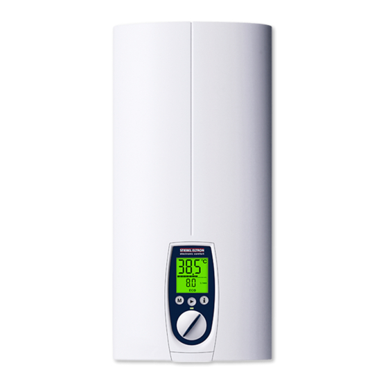
Vollelektronisch geregelter Durchlauferhitzer mit Mini-Funk-Fernbedienung | Fully
electronically controlled instantaneous water heater with mini wireless remote control |
Chauffe-eau instantané à régulation entièrement électronique avec télécommande radio |
Geheel elektronisch geregelde doorstromer met draadloze miniafstandsbediening |
Całkowicie elektronicznie regulowany przepływowy ogrzewacz wody, z miniaturowym
radiowym pilotem zdalnego sterowania | Plně elektronicky regulovaný průtokový ohřívač
s rádiovým dálkovým miniovladačem | Plne elektronicky regulovaný prietokový ohrievač s
mini rádiovým diaľkovým ovládaním
» DHE Connect 18/21/24
» DHE Connect 27
» DHE Touch 18/21/24
» DHE Touch 27
Advertisement
Table of Contents
Troubleshooting


Need help?
Do you have a question about the DHE Connect 18 and is the answer not in the manual?
Questions and answers