Advertisement
Quick Links
http://waterheatertimer.org/3-phase-water-heater.html
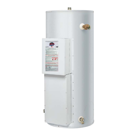
Commercial Electric Energy Saver
Energy Saver
Water Heater
IMMERSION AND SURFACE MOUNTED
THERMOSTAT MODELS
Manual 238-47174-00B - Save this manual for future reference
SERVICE
MANUAL
Troubleshooting Guide
and Instructions for Service
(To be performed ONLY by
qualifi ed service providers)
For Models
50(A)*(SF, CF)-**
80(A)*(SF, CF)-**
120(A)*(SF, CF)-**
*Denotes kW Rating
**Denotes Wiring Code
Advertisement

Related Manuals for Bock Water heaters Energy Saver 50A SF Series


Summary of Contents for Bock Water heaters Energy Saver 50A SF Series
- Page 1 http://waterheatertimer.org/3-phase-water-heater.html Energy Saver Commercial Electric Energy Saver Water Heater IMMERSION AND SURFACE MOUNTED THERMOSTAT MODELS SERVICE MANUAL Troubleshooting Guide and Instructions for Service (To be performed ONLY by qualifi ed service providers) For Models 50(A)*(SF, CF)-** 80(A)*(SF, CF)-** 120(A)*(SF, CF)-** *Denotes kW Rating **Denotes Wiring Code Manual 238-47174-00B - Save this manual for future reference...
- Page 2 This service manual is designed to aid service and maintenance professionals in the function, proper diagnosis and repair of Bock Water Heaters Commercial Electric Water Heaters. The text and illustrations in this manual provide step-by-step instructions to facilitate proper operation and troubleshooting procedures.
- Page 3 208/240 Volts kW Rating CF - Contactor w/Fuse (Immersion Thermostat) SF - Surface Thermostat w/Fuse Tank Capacity MFG FOR: BOCK WATER HEATERS, INC. 110 S. DICKINSON, MADISON WI 53703 Model Number Model No: 50SF-6, 208/240 Serial No: ZB2564812 Cap. 50(gal.)/189.3(liters)
- Page 4 GENERAL INFORMATION Contactor Models General Controls Layout Ground Lug Terminal Block Upper Control Box Fuse Block (s) Contactor (s) High Limit (ECO) Thermostat Direct Immersion Bulb Direct Immersion Bulb High Limit (ECO) Control Immersion Thermostat Lower Control Box Control Heating Elements Surface Mounted Thermostat Models General Controls Layout Ground Lug...
- Page 5 GENERAL INFORMATION 600V Surface Thermostat (w/Contactors) Models General Controls Layout Ground Lug Terminal Block Upper Control Box Contactor(s) High Limit (ECO) Control Surface Thermostats Lower Control Box Heating Elements...
- Page 6 GENERAL INFORMATION Surface Mounted Thermostats Surface mounted thermostats are mounted into a bracket above each heating element. The bracket holds the thermostat against the side of the tank responding to tank surface temperatures to sense a call for heat, set point temperature and high limit (ECO) activation.
- Page 7 GENERAL INFORMATION Surface Mounted Thermostats (w/Contactors) for 600V Models 600V models use contactors to deliver line voltage to the heating elements. However, rather than the immersion type high limit and thermostat devices, surface mounted thermostats are used to operate the control circuit of the water heater.
- Page 8 GENERAL INFORMATION Contactor Contactor operation is achieved by energizing an operating coil in response to a call for heat from the immersion thermostat. Upon a call for heat, one or more contactors will energize all heating elements simultaneously. The operating coils are voltage specifi c. When contactor replacement is required be sure to order the proper operating coil based on the voltage rating found on the rating plate located on the front of the water heater.
- Page 9 GENERAL INFORMATION Commonly Used Formulas (Single Phase) (Balanced 3 Phase) Watts Watts Volts Amps = Amps = Watts = Amps x Volts Ohms = Volts Volts x 1,732 Watts Common Service Wire 240V 1Ph Confi gurations BLACK GREEN Grounding Ungrounded Ungrounded 208 3Ph 240 3Ph...
- Page 10 SEQUENCE OF OPERATION Bock’s commercial electric water heaters can use either immersion thermostats (contactor models) or surface mounted thermostats. Sequence of operation for each confi guration is explained below. It would be impractical to show all wire diagrams applicable to both confi gurations. A “typical wiring diagram” is illustrated to aid in understanding the principles of the operating sequence.
- Page 11 SEQUENCE OF OPERATION Sequence of Operation: Line Voltage Surface Mounted Thermostats. 1. Line voltage is applied across terminals of fuse block or a terminal Fuse Block Terminal Bloc block. Line voltage continues down and connects to surface mounted thermostats at terminals L1 and L3. 2.
- Page 12 SEQUENCE OF OPERATION Sequence of Operation: Line Voltage 6 Element Configuration Shown 600V Surface Mounted Thermostats (w/Contactors). (9 Elements Possible) The system has two distinct circuits. Fuse Block Power Circuit - Line Voltage (600V) Transformer Control Circuit - 120V 60VA 1.
- Page 13 TROUBLESHOOTING The most common cause of improper electric water heater operation can be linked to heating element failure. When troubleshooting an electric water heater with the incidence of “no hot water” or “insuffi cient amount of hot water” it is always a good idea to check the heating elements fi rst following the procedure on Page 15.
- Page 14 TROUBLESHOOTING Quick Step Plan to Hot Water WARNING High voltage exposure. Use caution when 1. STOP, DANGER! Turn power “OFF” to water heater. making voltage checks to avoid hazard to 2. Check all wire connections to insure that they are snug and life or property.
- Page 15 SERVICE PROCEDURE Heating Element Testing Test for Open or Burned Out Element. WARNING 1. STOP, DANGER! Turn power “OFF” to water heater. High voltage exposure. To avoid hazard to life or property, be sure power is turned 2. Remove access cover from lower control box. Remove OFF to water heater while performing this insulation from inside of control box.
- Page 16 SERVICE PROCEDURE Line Voltage Testing Line Voltage Testing. WARNING High voltage exposure. To avoid hazard to Line voltage (single phase or three phase) will connect to a life or property, use extreme caution when terminal block or directly to a fuse block located inside the control panel.
- Page 17 SERVICE PROCEDURE Fuse Testing Fuse Testing. WARNING 1. STOP, DANGER! Turn power “OFF” to water heater. High voltage exposure. To avoid hazard to life or property, be sure power is turned 2. Open upper control box to allow access to fuse block. OFF to water heater while performing this procedure.
- Page 18 SERVICE PROCEDURE High Limit (ECO) Testing High Limit Control (ECO) Testing for WARNING Surface Thermostat Models (NOT including 600V) High voltage exposure. To avoid hazard to life or property, use extreme caution when 1. This procedure assumes line voltage and fuses are in working making voltage checks.
- Page 19 SERVICE PROCEDURE High Limit (ECO) Testing High Limit Control (ECO) Testing for WARNING 600V Surface Thermostat Models. High voltage exposure. To avoid hazard to life or property, use extreme caution when 1. This procedure assumes line voltage, transformer, fuses and making voltage checks.
- Page 20 SERVICE PROCEDURE High Limit (ECO) Testing High Limit Control (ECO) Testing for WARNING Contactor Models High voltage exposure. To avoid hazard Switch Contacts: to life or property, be sure power is turned Normally closed. OFF to water heater while performing this Open on rise @ 196°F ±...
- Page 21 SERVICE PROCEDURE Thermostat Testing Surface Mounted Thermostat. WARNING Operation Testing (NOT including 600V). High voltage exposure. To avoid hazard to Water in Tank is Cold with Power ON. life or property, use extreme caution when making voltage checks. 1. This procedure assumes line voltage, ECO and elements are in working order.
- Page 22 SERVICE PROCEDURE VIII Thermostat Testing 600V Surface Mounted Thermostat Models WARNING Operation Testing. High voltage exposure. To avoid hazard to life or property, use extreme caution when Water in Tank is Cold with Power ON. making voltage checks. 1. This procedure assumes line voltage, ECO, transformer, thermostat, and elements are in working order.
- Page 23 SERVICE PROCEDURE Thermostat Testing Immersion Thermostat Operation Testing. WARNING High voltage exposure. To avoid hazard to Thermostat Specifi cation. life or property, use extreme caution when Calibration: 184°F/176°F making voltage checks. Max Diff erential: 6°F Operating Range: 80°F to 180°F Providing the water temperature in tank is within the operating range of the thermostat, checking thermostat operation can be as simple as rotating the thermostat dial and listening to the contactor(s) to see if they respond to a call...
- Page 24 SERVICE PROCEDURE Contactor Testing Contactor Operation Testing. WARNING High voltage exposure. To avoid hazard to life or property, use extreme caution when making voltage checks. Noisy Contactor. Noisy or chattering contactor operation in most cases is due to voltage variations being supplied to the water heater. Extended periods of voltage variations will cause damage to the operating coil of the contactor causing noisy operation.
- Page 25 SERVICE PROCEDURE Contactor Testing Contactor Operation Testing (continued). WARNING High voltage exposure. To avoid hazard to This procedure assumes control circuit is operating correctly. life or property, use extreme caution when Providing the water temperature in tank is within the operating making voltage checks.
- Page 26 SERVICE PROCEDURE Thermostat Removal and Replacement Surface Mounted Thermostat Removal and Replacement WARNING High voltage exposure. To avoid hazard 1. STOP, DANGER! Turn power “OFF” to water heater. to life or property, be sure power is turned 2. Remove access cover from lower control. Remove insulation OFF to water heater while performing this from inside of control box.
- Page 27 SERVICE PROCEDURE Thermostat Removal and Replacement Immersion Thermostat Removal and Replacement WARNING High voltage exposure. To avoid hazard 1. STOP, DANGER! Turn power “OFF” to water heater. to life or property, be sure power is turned 2.Turn off cold water supply to heater. Connect hose to drain OFF to water heater while performing this spigot of water heater and route to an open drain.
- Page 28 SERVICE PROCEDURE XIII Contactor Model High Limit (ECO) Control Removal and Replacement Contactor Model High Limit (ECO) Control WARNING Removal and Replacement. High voltage exposure. To avoid hazard 1. STOP, DANGER! Turn power “OFF” to water heater. to life or property, be sure power is turned OFF to water heater while performing this 2.Turn off cold water supply to heater.
- Page 29 SERVICE PROCEDURE 600V Model High Limit (ECO) Control Removal and Replacement 600V Surface Thermostat Model High Limit (ECO) Control WARNING Removal and Replacement. High voltage exposure. To avoid hazard 1. STOP, DANGER! Turn power “OFF” to water heater. to life or property, be sure power is turned OFF to water heater while performing this 2.
- Page 30 SERVICE PROCEDURE Heating Element Removal and Replacement Heating Element Removal and Replacement. WARNING High voltage exposure. To avoid hazard 1. STOP, DANGER! Turn power “OFF” to water heater. to life or property, be sure power is turned 2. Turn off cold water supply to heater. Connect hose to drain OFF to water heater while performing this spigot of water heater and route to an open drain.
- Page 31 SERVICE PROCEDURE Anode Rod Inspection and Replacement Anode Rod Inspection and Replacement. WARNING High voltage exposure. To avoid hazard 1. STOP, DANGER! Turn power “OFF” to water heater. to life or property, be sure power is turned 2. Turn off cold water supply to heater. Connect hose to drain OFF to water heater while performing this spigot of water heater and route to an open drain.
- Page 32 GENERIC PARTS LIST TERMINAL BLOCKS FUSE BLOCKS CONTACTORS FUSES GROUND LUGS CONTACTOR COILS TRANSFORMER (600V ONLY) 11/11A 12/12A...
- Page 33 GENERIC PARTS LIST Item Description Item Description Anode Rod Lower Control Box Cover Hot Water Outlet Nipple Heating Element Plug T&P Nipple Heating Element Gasket T&P Coupling Cold Water Inlet Nipple T&P Relief Valve Plastic Snap Bushing High Limit Switch Lower Control Box Surface High Limit Switch Upper Control Box...
- Page 34 NOTES...
- Page 35 NOTES...
- Page 36 Madison, Wisconsin For U.S. and Canada fi eld service, contact your professional installer or local Bock Water Heaters sales representative Sales/608-227-3311 Fax/608-327-3311 Application & Sizing/608-227-3311 Fax/608-327-3311 Technical Support/888-784-8322 Fax/610-683-9208 Warranty/608-227-3319 Fax/608-327-3300 Email sales@bockwaterheaters.com www.bockwaterheaters.com...
Need help?
Do you have a question about the Energy Saver 50A SF Series and is the answer not in the manual?
Questions and answers