Table of Contents
Advertisement
Quick Links
Advertisement
Table of Contents

Related Manuals for IBASE Technology FWA8208 Series

Summary of Contents for IBASE Technology FWA8208 Series
- Page 1 FWA8208 Series Networking Appliance Users Manual Version: 1.1...
-
Page 2: Table Of Contents
Chapter 14 Watchdog Timer Configuration ..................33 Chapter 15 Digital I/O Sample Configuration ..................37 Chapter 16 Drivers Installation ......................42 Appendix-A I/O Port Address Map ....................... 53 Appendix-B Interrupt Request Lines (IRQ) ................... 53 Appendix-C FWA8208 Series Configurations ..................54... - Page 3 Foreword To prevent damage to the system board, please handle it with care and follow the measures below, which are generally sufficient to protect your equipment from static electricity discharge: When handling the board, use a grounded wrist strap designed for static discharge elimination grounded to a metal object before removing the board from the antistatic bag.
-
Page 4: Chapter 1 Introduction
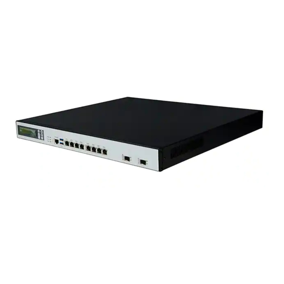
Chapter 1 Introduction FWA8208 series was specifically designed for the network security & management market. Network Security Applications: • Firewall • Unified Threat Management (UTM) • Virtual Private Network (VPN) • Proxy Server • Caching Server Network Management Applications: • Load balancing •... -
Page 5: Chapter 2 System Specification
Chapter 2 System Specification Product Name FWA8208 Form Factor 19” 1U Mainstream Networking Product Motherboard MB967 Intel® LGA1155 Series Processors Chipset Intel® Panther Point C216 PCH Intel® Xeon E3-1275 v2 Intel® Xeon E3-1225 v2 Intel® Core i7-3770 ... - Page 6 Operation Humidity 5% ~ 95% Certifications CE, FCC IBP161: 4-port RJ-45 10/100/1000 Copper LAN Module Card IBP162: 2-port 10 GbE SFP+ LAN Module Card Compatible Front IBP163: 2+2 ports GbE Copper or SFP LAN Module Card Expansion Cards ...
-
Page 7: Chapter 3 Hardware Configuration
Chapter 3 Hardware Configuration Jumper Locations on MB967... - Page 8 Jumper Settings on MB967 JP6, JP5, JP4: Bypass LANs & Reboot Setting Power ON, JP6,JP5 Power OFF Power ON OS run Setting Function software Normal Bypass Normal Bypass Normal Bypass JP4 Pin 1-2 & 3-4 System will bypass Open LANs upon the time ...
- Page 9 JP9: ATX & AT Mode Select Setting Function AT Mode Short/Closed (Default) ATX Mode Open J17: PCIE1 & PCIE2 Golden Finger PCI-e Configuration Setting Function Remarks Combine to For CPU with Open 1x16 1x16 support Short / Separate Default for CPU Closed to2x8 with 2x8 support...
- Page 10 Connector Locations on MB967...
- Page 11 CN1: USB 3.0 Box Header CN2: COM1 RJ45 Connector Pin # Signal Name (RS-232) RTS, Request to send DTR, Data terminal ready TXD, Transmit data Ground Ground RXD, Receive data DSR, Data set ready CTS, Clear to send CN3: CFast Connector CN4: USB Connector CN5, CN9: LAN Connectors CN7, CN8: SATA HDD Connector...
- Page 12 J4: COM2 Serial Port Pin # Signal Name (RS-232) DCD, Data carrier detect RXD, Receive data TXD, Transmit data DTR, Data terminal ready Ground DSR, Data set ready RTS, Request to send CTS, Clear to send RI, Ring indicator No Connect. J5: ATX 12V Power Connector Signal Name Pin #...
- Page 13 J20, J21: USB 2.0 Pin Header FAN1, 2, 3: System Fan Power Connector FAN1/2/3 are 4-pin headers for System fan power. Pin # Signal Name Ground +12V Rotation detection Control CPU_FAN1: CPU Fan Power Connector Pin # Signal Name Ground +12V Rotation detection Control...
- Page 14 Front Panel Features Console Management Port Optional LEDs Eth1 Front Expansion Card Rear Panel Features FWA8208 & FWA8208-2SLOT One or two 3x Smart Fans 300W Power Supply Add-on Card Expansion Slot Opening FWA8208-RPSU 275W 1+1 Redundant Power Supply One Add-on Card Expansion Slot Opening...
-
Page 15: Chapter 4 Console Mode Information
Chapter 4 Console Mode Information FWA8208 supports output information via Console in BIOS level. Prepare a computer as client loaded with an existing OS such as Windows XP and Windows 7. Connect client computer and FWA8208 with NULL Modem cable. Follow the steps below to configure the Windows Hyper Terminal application setting: 1. - Page 16 4. Please make the port settings to Baud rate 19200, Parity None, Data bits 8, Stop bits 1 5. Power on FWA8208. Press <Tab> key to enter BIOS setup screen in Console mode. Press <Del> key to enter BIOS setup screen in mode.
-
Page 17: Chapter 5 Open The Chassis
Chapter 5 Open the Chassis Fig. 5-2 Take off six screws and open the top lead Fig. 5-3 The base stand Chapter 6 Installing DDR3 Memory Install system memory by pulling the socket’s arm and pressing it into the slot gently. Fig. -
Page 18: Chapter 7 Installing Compactflash Card
Chapter 7 Installing CompactFlash Card Insert CompactFlash card into the socket. Fig. 7-1 Insert CompactFlash Card into the Fig. 7-2 Completion of CompactFlash Card CF interface connection Chapter 8 Removing and Installing the Battery Press the metal clip back to eject the button battery. Replace it with a new one by pressing the battery with fingertip to restore the battery Fig. -
Page 19: Chapter 9 Installing 2.5" Hdd (Fwa8208 & Fwa8208-Rpsu)
Chapter 9 Installing 2.5” HDD (FWA8208 & FWA8208-RPSU) Front Fig. 9- Take off two screws on bottom to Fig. 9-2 Fasten the four screws to lock HDD and remove 2.5” HDD bracket. bracket together. Fig. 9-3 Push HDD into connector Fig. -
Page 20: Chapter 10 Installing Optional Dual 2.5" Hdd Kit
Chapter 10 Installing Optional Dual 2.5” HDD Kit The following is for optional Dual 2.5” HDD kit: Fig. 10-2 Fasten the screws to lock 2.5” HDD Fig. 10-1 Push eight shock-absorbent pads to fasten HDD bracket. bracket and bracket together. Fig. -
Page 21: Chapter 11 Installing Add-On Card
Chapter 11 Installing Add-on Card Fig. 11-1 Loosen screw on slot bracket. Fig. 11-2 Slide in PCI-e add-on card. Fig. 11-3 Fix the add-on card Chapter 12 Installing Mini PCI-e Card Fig. 12-1 Insert Mini PCI-e card. Fig. 12-2 Push down Mini PCI-e card. -
Page 22: Chapter 13 Bios Information
Chapter 13 BIOS Information This setup allows you to view processor configuration used in your computer system and set the system time and date. Main Settings Aptio Setup Utility – Copyright © 2011 American Megatrends, Inc. Main Advanced Chipset Boot Security Save &... - Page 23 Above 4G Decoding Enables or Disables 64bit capable devices to be decoded in above 4G address space (only if system supports 64 bit PCI decoding). PCI Latency Timer Value to be programmed into PCI Latency Timer Register. VGA Palette Snoop Enables or disables VGA Palette Registers Snooping.
- Page 24 Unpopulated Links In order to save power, software will disable unpopulated PCI Express links, if this option set to ‘Disable Link’. ACPI Settings Aptio Setup Utility Advanced Main Chipset Boot Security Save & Exit ACPI Settings → ← Select Screen Enable Hibernation [Enabled] ↑↓...
- Page 25 CPU Configuration This section shows the CPU configuration parameters. Aptio Setup Utility Advanced Main Chipset Boot Security Save & Exit CPU Configuration Intel(R) Xeon(R) CPU E3-1225 V2 3.20GHz CPU Signature 306a8 Microcode Patch CPU Speed 3200 MHz Processor Cores Intel HT Technology Not Supported Intel VT-x Technology Supported...
- Page 26 SATA Mode Selection (1) IDE Mode. (2) AHCI Mode. (3) RAID Mode. Shutdown Temperature Configuration Aptio Setup Utility Advanced Main Chipset Boot Security Save & Exit APCI Shutdown Temperature [Disabled] ACPI Shutdown Temperature Set function Disabled or 70/75/80/85/90/95 ℃ AMT Configuration Aptio Setup Utility Advanced Main...
- Page 27 Acoustic Management Configuration Aptio Setup Utility Advanced Main Chipset Boot Security Save & Exit Acoustic Management Configuration Automatic Acoustic Management [Disabled] → ← Select Screen ↑↓ Select Item Enter: Select Change Field F1: General Help F2: Previous Values F3: Optimized Default F4: Save ESC: Exit USB Configuration...
- Page 28 F81866 Super IO Configuration Aptio Setup Utility Advanced Main Chipset Boot Security Save & Exit Super IO Configuration → ← Select Screen F81866 Super IO Chip F81866 ↑↓ Select Item ► Serial Port 0 Configuration Enter: Select ► Serial Port 1 Configuration Change Field Power Failure [Always off]...
- Page 29 Console Redirection Settings Aptio Setup Utility Advanced Main Chipset Boot Security Save & Exit Emulation: ANSI: COM0 Console Redirection Settings Extended ASCII char Set. VT100: ASCII char Terminal Type [VT100+] Set. VT100+: Extends Bits per second [115200] VT100 to support color, Data Bits Function keys, etc.
- Page 30 Wake on LAN Enable or disable integrated LAN to wake the system. (The Wake On LAN cannot be disabled if ME is on at Sx state.) SLP_S4 Assertion Width Select a minimum assertion width of the SLP_S4# signal. PCI Express Configuration Chipset Main Advanced...
- Page 31 System Agent (SA) Configuration Aptio Setup Utility Chipset Main Advanced Boot Security Save & Exit System Agent Bridge Name IvyBridge System Agent RC Version 1.1.0.0 VT-d Capability Supported VT-d [Enabled] CHAP Device (B0:D7:F0) [Disabled] → ← Select Screen Thermal Device (B0:D4:F0) [Disabled] ↑↓...
- Page 32 Boot Settings Aptio Setup Utility Boot Main Advanced Chipset Security Save & Exit Boot Configuration Setup Prompt Timeout Bootup NumLock State [On] Quiet Boot [Disabled] Fast Boot [Disabled] → ← Select Screen CSM16 Module Version 07.68 ↑↓ Select Item Enter: Select GateA20 Active [Upon Request] Change Field...
- Page 33 Launch PXE OpROM policy Controls the execution of UEFI and Legacy PXE OpROM. Launch Storatge OpROM policy Controls the execution of UEFI and Legacy Storage OpROM. Launch Video OpROM policy Controls the execution of UEFI and Legacy Video OpROM. Other PCI device ROM priority For PCI devices other than Network, Mass storage or Video defines which OpROM to launch.
-
Page 34: Chapter 14 Watchdog Timer Configuration
Save Changes Save Changes done so far to any of the setup options. Discard Changes Discard Changes done so far to any of the setup options. Restore Defaults Restore/Load Defaults values for all the setup options. Save as User Defaults Save the changes done so far as User Defaults. - Page 35 printf(" Parameter incorrect!!\n"); return (1); bTime = strtol (argv[1], endptr, 10); printf("System will reset after %d seconds\n", bTime); if (bTime) EnableWDT(bTime); else DisableWDT(); } return 0; //--------------------------------------------------------------------------- void EnableWDT(int interval) unsigned char bBuf; bBuf = Get_F81866_Reg(0x2B); bBuf &= (~0x20); Set_F81866_Reg(0x2B, bBuf); //Enable WDTO Set_F81866_LD(0x07);...
- Page 36 //--------------------------------------------------------------------------- #include "F81866.H" #include <dos.h> //--------------------------------------------------------------------------- unsigned int F81866_BASE; void Unlock_F81866 (void); void Lock_F81866 (void); //--------------------------------------------------------------------------- unsigned int Init_F81866(void) unsigned int result; unsigned char ucDid; F81866_BASE = 0x4E; result = F81866_BASE; ucDid = Get_F81866_Reg(0x20); if (ucDid == 0x07) //Fintek 81866 goto Init_Finish;...
- Page 37 return Result; //--------------------------------------------------------------------------- //--------------------------------------------------------------------------- // THIS CODE AND INFORMATION IS PROVIDED "AS IS" WITHOUT WARRANTY OF ANY // KIND, EITHER EXPRESSED OR IMPLIED, INCLUDING BUT NOT LIMITED TO THE // IMPLIED WARRANTIES OF MERCHANTABILITY AND/OR FITNESS FOR A PARTICULAR // PURPOSE. //--------------------------------------------------------------------------- #ifndef __F81866_H #define __F81866_H...
-
Page 38: Chapter 15 Digital I/O Sample Configuration
Chapter 15 Digital I/O Sample Configuration Filename:Main.cpp //--------------------------------------------------------------------------- // THIS CODE AND INFORMATION IS PROVIDED "AS IS" WITHOUT WARRANTY OF ANY // KIND, EITHER EXPRESSED OR IMPLIED, INCLUDING BUT NOT LIMITED TO THE // IMPLIED WARRANTIES OF MERCHANTABILITY AND/OR FITNESS FOR A PARTICULAR // PURPOSE. - Page 39 Dio5SetOutput(0x00); //clear DIO = Dio5GetInput() & 0x0F; Dio5SetOutput(0x00); //clear DIO = Dio5GetInput() & 0x0F; if (DIO != 0x0A) printf("The Fintek 81865 digital IO abnormal, abort.\n"); return(1); }//if (DIO != 0x0A) Dio5SetOutput(0xA0); //clr# is high Dio5SetOutput(0xF0); //clk and clr# is high Dio5SetOutput(0xA0);...
- Page 40 ucBuf = Get_F81865_Reg(0x30); ucBuf |= 0x01; Set_F81865_Reg(0x30, ucBuf); Set_F81865_Reg(0xA0, 0x00); //define as input mode Set_F81865_Reg(0xA3, 0xFF); //push pull mode //--------------------------------------------------------------------------- void Dio5SetOutput(unsigned char NewData) Set_F81865_LD(0x06); //switch to logic device 6 Set_F81865_Reg(0xA1, NewData); //--------------------------------------------------------------------------- unsigned char Dio5GetInput(void) unsigned char result; Set_F81865_LD(0x06); //switch to logic device 6 result = Get_F81865_Reg(0xA2);...
- Page 41 ucDid = Get_F81865_Reg(0x20); if (ucDid == 0x07||ucDid == 0x10) //Fintek 81865/66 goto Init_Finish; } F81865_BASE = 0x2E; result = F81865_BASE; ucDid = Get_F81865_Reg(0x20); if (ucDid == 0x07||ucDid == 0x10) //Fintek 81865/66 goto Init_Finish; } F81865_BASE = 0x00; result = F81865_BASE; Init_Finish: return (result);...
- Page 42 #ifndef __F81865_H #define __F81865_H //--------------------------------------------------------------------------- #define F81865_INDEX_PORT (F81865_BASE) #define F81865_DATA_PORT (F81865_BASE+1) //--------------------------------------------------------------------------- #define F81865_REG_LD 0x07 //--------------------------------------------------------------------------- #define F81865_UNLOCK 0x87 #define F81865_LOCK 0xAA //--------------------------------------------------------------------------- unsigned int Init_F81865(void); void Set_F81865_LD( unsigned char); void Set_F81865_Reg( unsigned char, unsigned char); unsigned char Get_F81865_Reg( unsigned char); //--------------------------------------------------------------------------- #endif //__F81865_H...
-
Page 43: Chapter 16 Drivers Installation
Chapter 16 Drivers Installation This section describes the installation procedures for software and drivers under the Windows. The software and drivers are included with the board. If you find the items missing, please contact the vendor where you made the purchase. - Page 44 3. When the Welcome screen to the Intel® Chipset Device Software appears, click Next to continue. 4. Click Yes to accept the software license agreement and proceed with the installation process. 5. On the Readme File Information screen, click Next to continue the installation.
- Page 45 6. The Setup process is now complete. Click Finish to restart the computer and for changes to take effect. VGA Drivers Installation NOTE: Before installing the Intel(R) C216 Chipset Family Graphics Driver, the Microsoft .NET Framework 3.5 SPI should be first installed. To install the VGA drivers, follow the steps below.
- Page 46 3. When the Welcome screen appears, click Next to continue. 4. Click Yes to to agree with the license agreement and continue the installation. 5. On the Readme File Information screen, click Next to continue the installation of the Intel® Graphics Media Accelerator Driver.
- Page 47 6. On Setup Progress screen, click Next to continue. 7. Setup complete. Click Finish to restart the computer and for changes to take effect. LAN Drivers Installation 1. Insert the CD that comes with the board. Click Intel and then Intel(R) Q7 Series Chipset Drivers.
- Page 48 3. Click Install Drivers and Software. 4. When the Welcome screen appears, click Next. 5. Click Next to to agree with the license agreement.
- Page 49 6. Click the checkbox for Drivers in the Setup Options screen to select it and click Next to continue. 7. The wizard is ready to begin installation. Click Install to begin the installation. 8. When InstallShield Wizard is complete, click Finish.
- Page 50 Intel® Management Engine Interface Follow the steps below to install the Intel Management Engine. 1. Insert the CD that comes with the board. Click Intel and then Intel(R) AMT 8.0 Drivers. 2. When the Welcome screen to the InstallShield Wizard for Intel® Management Engine Components, click the checkbox for Install Intel®...
- Page 51 3. Click Yes to to agree with the license agreement. 4. When the Setup Progress screen appears, click Next. Then, click Finish when the setup progress has been successfully installed.
- Page 52 Intel® USB 3.0 Drivers 1. Insert the CD that comes with the board. Click Intel and then Intel(R) C216 Series Chipset Drivers. 2. Click Intel(R) USB 3.0 Drivers. 3. When the Welcome screen to the InstallShield Wizard for Intel® USB 3.0 eXtensible Host Controller Driver, click Next.
- Page 53 4. Click Yes to to agree with the license agreement and continue the installation. 5. On the Readme File Information screen, click Next to continue the installation of the Intel® USB 3.0 eXtensible Host Controller Driver. 6. Setup complete. Click Finish to restart the computer and for changes to take effect.
-
Page 54: Appendix-A I/O Port Address Map
Appendix-A I/O Port Address Map Each peripheral device in the system is assigned a set of I/O port addresses which also becomes the identity of the device. The following table lists the I/O port addresses used. Address Device Description 000h - 01Fh DMA Controller #1 020h - 03Fh Interrupt Controller #1... -
Page 55: Appendix-C Fwa8208 Series Configurations
Appendix-C FWA8208 Series Configurations The following lists the available SKUs of FWA8208 for different system requirement. FWA8208 2.5” HDD x1, PCI-e add-on card rear expansion x1, front panel expansion card x1, 300W PSU MB967 x1 IP331 x1: 1-to-1 Riser Card ...
Need help?
Do you have a question about the FWA8208 Series and is the answer not in the manual?
Questions and answers