Table of Contents
Advertisement
Operating Instructions
Ident No. 822-006
BAUR Prüf- und Messtechnik GmbH
Raiffeisenstrasse 8, A-6832 Sulz / Austria
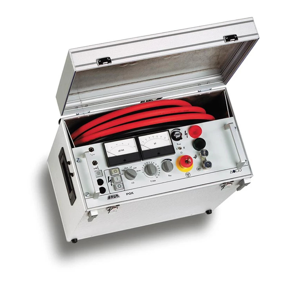
High Voltage Testing Sets
PGK 50 and PGK 80
For High Voltage Tests up to:
50 kV DC (= PGK50) and 80 kV DC (= PGK80)
01/00
e-mail: headoffice@baur.at
internet: http://www.baur.at
0-1
Tel +43 / 55 22 / 49 41-0
Fax +43 / 55 22 / 49 4 13
Advertisement
Table of Contents


Need help?
Do you have a question about the PGK 50 and is the answer not in the manual?
Questions and answers