
Related Manuals for Baur Syscompact 2000


Summary of Contents for Baur Syscompact 2000
- Page 1 User manual Syscompact 2000 Ref. No.822-117 02/2009 BAUR Prüf- und Messtechnik GmbH E-Mail: headoffice@baur.at Tel. +43/5522/4941-0 Raiffeisenstrasse 8, A-6832 Sulz/Austria internet: www.baur.at Fax +43/5522/4941-3...
- Page 2 In any case, read carefully! Important information text. Copyright © by BAUR Prüf- und Messtechnik GmbH, A-6832-Sulz / Austria. All rights reserved. No part of this publication may be reproduced, transmitted, stored in a data processing system or translated into another language without the written permission of BAUR / Sulz, Austria.
- Page 3 Operating Instructions. It is the responsibility of the customer to ensure that only authorized persons may be allowed to use the Syscompact 2000. The operator must immediately inform his superior about any conditions of the unit that could affect safety.
- Page 4 Operating Instructions! We draw attention in addition to the ‘General Sales and Business Conditions’ of: BAUR Prüf- und Messtechnik GmbH, Raiffeisenstrasse 8 A-6832-Sulz / Austria...
-
Page 5: Table Of Contents
SA 32 K High voltage socket board CS 32/2 Cable drum rack KTG M3 Connections / operation of IRG 2000 Using the Syscompact 2000 Important notices Discharge- and grounding rod Connecting the Syscompact 2000 4.3.1 Connection to different cable types Switch high voltage on and off 4.4.2 HV on... -
Page 6: Application
1 Application Syscompact 2000 is a compact designed, fully enclosed cable fault location system for prelocation and pin pointing of high impedance, low impedance and intermittent cable faults of low and medium voltage cables. Easy operation and use of latest fault location methods in combination with efficient instruments enable a rapid and reliable fault location. -
Page 7: Theory Of Cable Fault Prelocation
2 Theory of cable fault pre-location At shown examples the so called test lead is already subtracted. Therefore in the left cursor (zero cursor) is located at end of test lead (= beginning of cable under test). 2.1 Echometer (Time Domain Reflection) The IRG sends a low voltage impulse into the cable under test. -
Page 8: Secondary Impulse Method
2.2 Secondary Impulse Method The IRG sends a low voltage impulse into the cable under test, it is reflected positively by the cable end. Not visible at this first measurement is the high resistive fault. A high voltage impulse released from the SSG ignites an arc at fault. - Page 9 Both curves are putted together by the IRG. At point negative reflection the location of fault is clearly visible. The distance is calculated as follows: t × Distance to fault = propagation velocity x time ...
-
Page 10: Impulse Current Method (Icm)
2.3 Impulse Current Method (ICM) A high voltage impulse released by a SSG to a faulty cable ignites a arc at fault position. The so created transient wave is moving between arc and connection point. The waves are picked up by the impulse current coupling SK1D... -
Page 11: Arrangement Of Instruments Within The System
3 Arrangement of instruments within the system 3.1 Front view 1) Signal lamp "SIM" on 2) Measuring range selector switch for mA meter 3) mA meter 4) Pull switch: Test / SSG 5) Pull switch: SA 32 / SSG 6) Low voltage input (e.g. audio frequency generator, ohmmeter etc.) 7) Mains connection 220V (240V), 50 / 60Hz or 110V (120V) 60Hz 8) Low voltage output 9) High voltage output max. -
Page 12: Rear View
3.2 Rear view 18) High voltage connecting line SSG - SA 32 19) Protection earth clamp SSG 20) Protection earth connection 21) Mains input SSG 22) Protection earth clamp SA 32 23) BNC connecting socket IRG 2000 24) High voltage input (from SSG) 25) High voltage output (to CS 32/2) -
Page 13: Sa 32 K
3.3 SA 32 The SA 32 offers the possibility of fault location according to the Secondary Impulse Method (SIM) respectively SIM-MIM (advanced SIM). In conjunction with a surge voltage generator type SSG, the SA 32 can be used as DC testing generator up to 32kV, or as fault conditioning instrument up to max. -
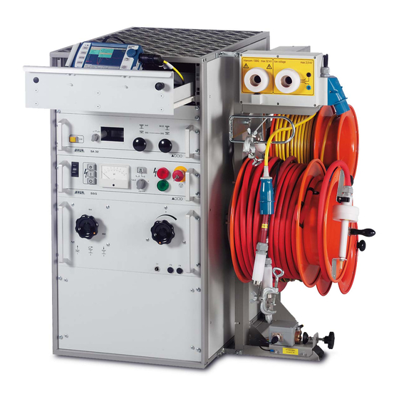
Page 14: Cable Drum Rack Ktg M3
3.6 Cable drum rack KTG M3 On the KTG M3 there are three different connection cables on lockable cable drums: mains cable earth cable high voltage cable Attention: For transportation the brakes must be locked. Mains cable Mains cable is connecting line between power supply and Syscompact. Mains connection For mains connection a 220V power supply is required with a earth connection. -
Page 15: Connections / Operation Of Irg 2000
30) Cable guiding bow 31) 220V plug-in socket 32) 220V plug (mains input) 33) Cable drum with mains cable 34) Lockable brake 35) Cable drum with earth cable 36) Cable drum with high voltage cable 37) High voltage output (9) 38) LV output (8) 39) Earth terminal (10) 40) Micro switch control for high voltage plug... -
Page 16: Using The Syscompact 2000
4 Using the Syscompact 2000 4.1 Important notices The Syscompact 2000 should only be used to test disconnected cables. Before connecting the system, the cable has to be disconnected from the supply and the discharging/grounding has to be verified. The local legal and companies’... - Page 17 After a flashover in the cable or after interrupting the test e.g. by pressing the emergency-off button, the DUT still can carry voltage. Therefore the DUT firstly has to be discharged and afterwards grounded before handling. For correct discharging and grounding, the discharge/grounding – rod has to be connected to protection/station earth correctly.
-
Page 18: Connecting The Syscompact 2000
Connecting of safety earth Connect the Syscompact 2000 with the included safety-earth-line (yellow-green) to the safety-earth-connector (B) and to the to the station earth. Use the foreseen clamps for this. For best possible earthing take care for a short connection (minimum of cable length) between safety-earth-connector and station earth. - Page 19 Please ensure that adequate precautions, as described in the chapter „discharging and grounding“ and general safety instruction are followed HV Test lead Protection earth conductor termination Syscompact 2000 sheath steady protection earth / station earth Operation of Syscompact 2000 only in vertical position!
-
Page 20: Connection To Different Cable Types
4.3.1 Connection to different cable types Connection to a 3-phase shielded cable Connection to a 1-phase shielded cable Connection to a 3-phase unshielded cable with neutral conductor... -
Page 21: Switch High Voltage On And Off
4.4 Switch high voltage on and off 4.4.2 HV on Press main switch, green lamp lights Regulating transformer to left limit stop and emergency off not pressed Press “high voltage ready”, red lamp lights Press “high voltage on”, button and red lamp lights... -
Page 22: Hv Off
Pay attention that during discharge, different and rather high discharge time constants can occur, depending on the connected test object capacity and the selected discharge rod. (Preferably by using the BAUR Discharge / Earthing Rod) -
Page 23: High Voltage Testing
The functionality of high voltage testing is mainly used to detect the breakdown voltage of a fault with the Syscompact 2000. Pull switch 4 on the SA 32 and set it to position .test.. After switching on, set pulse selector switch on the SSG (operating manual SSG, no. -
Page 24: Cable Fault Prelocation Methods
6 Cable fault pre-location methods Danger! High-voltage When using surge mode: Cordon off syscompact at a distance of 1.5 m Persons must stand only outside the barrier All measurements are started by pressing knob of IRG 2000 for two seconds. For more detailed help of using IRG 2000 please have a look to IRG 2000 user manual and the instructions displayed in the status bar. -
Page 25: Sim - Mim
Range and Gain are adjusted automatically. Automatic cursor setting indicates the position of fault or cable end. If adjustment is required, click the cursor key and select cursor by pressing knob - adjust cursor by rolling knob. 6.2 SIM – MIM For cable faults R >... -
Page 26: Application Sim - Mim With Dc Voltage (Sim Dc)
Increase voltage 20-50% higher than ignition voltage of fault, release impulse by pressing single impulse button. IRG 2000 shows secondary measurement – fault location at negative reflection case sufficient secondary measurement further three measurements of MIM could be used to locate the fault. Add this measurement by clicking on the button “line select”... - Page 27 Start operation with Syscompact 2000 as described under 6.2 After switching on SSG, pulse selection switch is set to DC “=”. Select SIM – MIM at IRG 2000 and start measurement. The IRG 2000 records an echogram showing the end of the cable (best condition image). IRG 2000 is now waiting for a HV impulse.
-
Page 28: Impulse Current Method (Icm / Surge Method)
6.4 Impulse Current Method (ICM / Surge Method) For cable faults R > 100Ω, intermittent and wet faults. Approximate fault distance should be > 150m (500ft) Put the high voltage plug into the HV socket (9). Push both pull rods at SA 32 in Switch HV on, SSG to permanent impulse, increase voltage up to a clearly visible breakdown sound is audible. -
Page 29: Accurate Fault Location (Pin Pointing)
7 Accurate fault location (pin pointing) Danger! High-voltage When using surge mode: Cordon off syscompact at a distance of 1.5 m Persons must stand only outside the barrier Accurate fault location is made with UL 30, BM 30 and SSG according to the acoustic location method. -
Page 30: Technical Data
8 Technical data IRG 2000 Output voltage of transmitting pulse 10...60V Pulse width of transmitting pulse 40ns – 10 µs Voltage withstand pulse echo mode 400V AC (50-60 Hz) Output impedance 10 - 250 Ohm adjustable Measuring ranges (at v / 2 = 80 m / µs) 0-65 km Real time sampling rate 200 MHz (5ns) -
Page 31: Maintenance
9 Maintenance The Surge Voltage Generators SSG of Syscompact 2000 has a surge capacitor available which consists of four isolated partial capacitors. Even in the turned off condition these partial capacitors can show substantial residual charges. For safety reasons, actions which involve opening the instrument may therefore be only carried out by instructed and authorized service personnel. -
Page 32: Accessories & Options
10 Accessories & options 10.1 External emergency switch-off (option) To perform save tests even in unclear locality an external emergency-off button with signal lamps is available. BAUR Prüf- und Messtechnik GmbH Raiffeisenstrasse 8, A-6832 Sulz / Austria Tel. +43/5522/4941-0 Fax.
Need help?
Do you have a question about the Syscompact 2000 and is the answer not in the manual?
Questions and answers