
Related Manuals for Pepperl+Fuchs UC F77 Series


Summary of Contents for Pepperl+Fuchs UC F77 Series
- Page 1 FACTORY AUTOMATION MANUAL UC***-F77 Series Configuring Ultrasonic Sensors with IO-Link Interface...
- Page 2 UC***-F77 series With regard to the supply of products, the current issue of the following document is ap- plicable: The General Terms of Delivery for Products and Services of the Electrical Indus- try, published by the Central Association of the Electrical Industry (Zentralverband Elektrotechnik und Elektroindustrie (ZVEI) e.V.) in its most recent version as well as the supplementary clause: "Expanded reservation of proprietorship"...
-
Page 3: Table Of Contents
UC***-F77 series Introduction................. 7 Content of this Document ..............7 Target Group, Personnel..............7 Symbols Used ..................7 Intended Use ..................8 General Safety Notes ................8 Declaration of Conformity ..............9 Product Description ..............10 Use and Application................10 Displays and Local Controls ............. - Page 4 UC***-F77 series Configuration and Analysis with DTM via IO-Link....25 Overview....................25 Sensor Information Menu Option............26 Output Configuration Menu Item ............26 Sensor Configuration Menu Option..........27 Analysis & Echo Suppression Menu Option........29 Observation Menu Option..............37 Service Menu Option................42 Information Menu Option..............43 Description of Sensor Parameters.......... 44 Sensor Information................44 Output –...
- Page 5 UC***-F77 series Sensor Configuration – Evaluation ..........52 8.4.1 Sound Beam Width................52 8.4.2 Echo Evaluation ................53 8.4.3 Evaluation Method ................54 8.4.4 Averages & Skip Count ..............55 8.4.5 Weighting of Former Measurement..........55 8.4.6 Allowed Deviation to the Former Measurement........ 56 8.4.7 Skip Time..................
- Page 6 UC***-F77 series 12 Appendix ................... 68 12.1 IO-Link Device Parameters ..............68...
-
Page 7: Introduction
UC***-F77 series Introduction Introduction Content of this Document This document contains information required to use the product in the relevant phases of the product life cycle. This may include information on the following: Product identification Delivery, transport, and storage Mounting and installation Commissioning and operation Maintenance and repair Troubleshooting... -
Page 8: Intended Use
UC***-F77 series Introduction Depending on the risk level, the warning messages are displayed in descending order as follows: Danger! This symbol indicates an imminent danger. Non-observance will result in personal injury or death. Warning! This symbol indicates a possible fault or danger. Non-observance may cause personal injury or serious property damage. -
Page 9: Declaration Of Conformity
UC***-F77 series Introduction If serious faults occur, stop using the device. Secure the device against inadvertent operation. In the event of repairs, return the device to your local Pepperl+Fuchs representative or sales office. Note! Disposal Electronic waste is hazardous waste. When disposing of the equipment, observe the current statutory requirements in the respective country of use, as well as local regulations. -
Page 10: Product Description
UC***-F77 series Product Description Product Description Use and Application The UC***-F77 series ultrasonic sensors use ultrasonic pulses to detect objects. The sensor emits ultrasound which is reflected by the object and received again by the sensor. The measured sound propagation time is used to determine the distance to the object (pulse-echo principle). - Page 11 UC***-F77 series Product Description The F77 compact housing design can be programmed and so adapted to various applications. You can program limits, output mode, output type, and sound beam width via the programming button on the sensor or the convenient IO-Link interface. Programming via the IO-Link also provides the option of setting many other parameters such as filter options, echo suppression, synchronization settings,...
-
Page 12: Displays And Local Controls
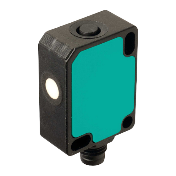
UC***-F77 series Product Description Displays and Local Controls Figure 2.2 1. Sonically-active area 2. Yellow LED 3. Green/red LED (Duo LED) 4. Programming button LED display for sensors with switching output Green LED Yellow LED Red LED In normal operation Error-free operation Switching state Fault (e.g., compressed air) -
Page 13: Accessories
UC***-F77 series Product Description LED display for sensors with analog output Green LED Yellow LED Red LED In normal operation Error-free operation Output state Fault (e.g., compressed air) Retains previous state (factory default setting, can be changed via IO-Link) Standby (high level for > 1 s at Flashing Retains previous state synchronization input) -
Page 14: Configuration Aids
UC***-F77 series Product Description 2.3.2 Configuration Aids The following configuration aids are available: Designation Description PACTware FDT frame application for operating IODDs and DTMs Pepperl + Fuchs PACTware Wizard for simple project and connection set-up of the ultrasonic Connection Wizard sensor in PACTware. -
Page 15: Installation
2. Check that all items are present and correct based on your order and the shipping documents. If you have any questions, please contact Pepperl+Fuchs. 3. Keep the original packing material in case you need to store or ship the unit at a later time. -
Page 16: Connection
UC***-F77 series Installation Mounting UC***-F77S sensors F77S sensors can be secured using either M3 cylinder head screws or an M18 nut. Tighten the M3 cylinder head screws with a maximum torque of 0.2 Nm. Tighten the M18 nut with a maximum torque of 1 Nm. Figure 3.2 Connection Note! -
Page 17: Commissioning Without Io-Link
UC***-F77 series Commissioning without IO-Link Commissioning without IO-Link Switch on the supply voltage. The operating indicator on the sensor lights up green. The sensor will now function using the preset parameters. Note! It is only possible to change configuration by programming with the programming button or by configuring via IO-Link! -
Page 18: Sensor Programming Via The Programming Button
UC***-F77 series Sensor Programming via the Programming Button Sensor Programming via the Programming Button Basic information about programming In terms of factory settings, the sensor can only be programmed during the first 5 minutes after switching on. This time is extended during the actual programming process. The option of programming the sensor is revoked if no programming activities take place for 5 minutes. -
Page 19: Programming Sensor Operating Modes (Sensor With Switching Output)
UC***-F77 series Sensor Programming via the Programming Button Programming Sensor Operating Modes (Sensor with Switching Output) The sensor features a 3-stage process for programming the sensor operating modes. In this programming routine you can program as follows: A) Output mode B) Output logic C) Sound beam width These stages of the process are programmed in succession. -
Page 20: Programming The Sensor Operating Modes (Sensor With Analog Output)
UC***-F77 series Sensor Programming via the Programming Button 1. Briefly press the programming button to navigate through the sound beam widths in succes- sion. Use this method to choose the required sound beam width. 2. Press and hold the push button for 2 seconds to save all performed settings and to return to normal operation. - Page 21 UC***-F77 series Sensor Programming via the Programming Button 1. Briefly press the programming button to navigate through the output types in succession. Se- lect the required output type. 2. Press the programming button for 2 seconds to change to the next programming step, the adjustment of the sound beam width.
-
Page 22: Commissioning With Io-Link Using Pactware And Dtm
UC***-F77 series Commissioning with IO-Link Using PACTware and DTM Commissioning with IO-Link Using PACTware and DTM Note! An M8 to M12 connection cable is necessary to connect the sensor to the IO-Link master. You can find suitable connection cables by visiting www.pepperl-fuchs.com and clicking on the product page for the relevant sensor. - Page 23 UC***-F77 series Commissioning with IO-Link Using PACTware and DTM Setting Up Sensor Communication using PACTware (Step-by-Step) 1. Launch PACTware by double-clicking on the PACTware icon. Figure 6.1 2. Click at the top left on Project (1). 3. Click on Host PC (2), then click the right mouse button and click Add device (3). Displays a window for selecting the device 4.
- Page 24 UC***-F77 series Commissioning with IO-Link Using PACTware and DTM 7. Double-click in the project on the DTM (5) here as example "UC250-F77-EP-IO-V31." The selected DTM interface is displayed. 8. Click on the icon to set up the connection (6). Data connection to the sensor is established. Status information "connected" will be displayed in the bottom left of the menu if connection is successful.
-
Page 25: Configuration And Analysis With Dtm Via Io-Link
UC***-F77 series Configuration and Analysis with DTM via IO-Link Configuration and Analysis with DTM via IO-Link Overview The sensor parameters are different for each device. These parameters are clearly set out in the DTM (Device Type Manager), with guidance being provided in the form of graphics for some of the parameters. -
Page 26: Sensor Information Menu Option
UC***-F77 series Configuration and Analysis with DTM via IO-Link Sensor Information Menu Option 42 mm Figure 7.2 Preprogrammed manufacturer and device information is displayed in the Sensor information menu option, as well as the number of operating hours. These are read-only fields. You can input application-specific tags to identify and mark your sensor in the system environment. -
Page 27: Sensor Configuration Menu Option
UC***-F77 series Configuration and Analysis with DTM via IO-Link Sensor Configuration Menu Option Overview of the Sensor Configuration menu option Figure 7.4 The sensor configuration menu option consists of 4 tabs Evaluation (with reduced and advanced view) Synchronization Echo loss and error handling Local controls Evaluation tab (advanced view) Figure 7.5... - Page 28 UC***-F77 series Configuration and Analysis with DTM via IO-Link Synchronization tab Figure 7.6 In the Synchronization tab, you can set the required synchronization mode if you want to suppress mutual interference when operating several UC***-F77-...-IO-.. sensors. Details of the individual synchronization modes can be found in the chapter "Synchronizing multiple sensors."...
-
Page 29: Analysis & Echo Suppression Menu Option
UC***-F77 series Configuration and Analysis with DTM via IO-Link Analysis & Echo Suppression Menu Option Figure 7.9 In some applications, machine parts or support bars within a tank obstruct the sensing area, preventing proper distance or level measurement. Using the Analysis & Echo Suppression menu option, you can visualize and analyze all echoes received by the ultrasonic sensor from one or a series of measurements, as well as suppress the disruptive objects in the sensing area. - Page 30 UC***-F77 series Configuration and Analysis with DTM via IO-Link Menu Description Figure 7.10 No. Name Description Echo sampling In the "Echo sampling" area, you can choose whether to record a single value, 50 values or continuous data. Using the continuous display also provides you with an alignment aid.
- Page 31 UC***-F77 series Configuration and Analysis with DTM via IO-Link No. Name Description Load file You can load previously-saved echo samples to the DTM by pressing the "Load file" button, allowing you to assess or evaluate the samples. Note: You can only load a saved file if disconnected from the sensor.
- Page 32 UC***-F77 series Configuration and Analysis with DTM via IO-Link Details about sampled echoes Using an echo sample with manual echo suppression as an example, the following sets out the graphic elements of information in the display area. Figure 7.11 No. Name Description Suppression area A rectangle indicates the specified suppression area.
- Page 33 UC***-F77 series Configuration and Analysis with DTM via IO-Link No. Name Description Details of the Clicking on a column from the echo sample displays the following selected echo detailed information in the "Details of the selected echo" area: Echo number: The echo number is a consecutive number which numbers the echoes shown in the graphic from left to right.
- Page 34 UC***-F77 series Configuration and Analysis with DTM via IO-Link Application Information for Echo Suppression In order to be able to suppress echoes, you first have to set the "Echo suppression" parameter to "enabled," provided that the parameter is not already set accordingly in the connected sensor.
- Page 35 UC***-F77 series Configuration and Analysis with DTM via IO-Link Example In terms of the following echo sample, the echo labeled with the red arrow should be suppressed. The echo labeled with the green arrow echo comes from the object that is to be detected (e.g., the level surface).
- Page 36 UC***-F77 series Configuration and Analysis with DTM via IO-Link The graphic with set suppression area for an interior application is as follows: Figure 7.13 Note! The boundaries of suppression areas can also be adjusted directly within the graphic by left- clicking and dragging with the mouse.
-
Page 37: Observation Menu Option
UC***-F77 series Configuration and Analysis with DTM via IO-Link Observation Menu Option 42 mm 42 mm Figure 7.14 You can use the Observation menu option to track and record data from the ultrasonic sensor over time, as well as the corresponding behavior of the switching and analog outputs. You can choose from the "Visual observation"... - Page 38 UC***-F77 series Configuration and Analysis with DTM via IO-Link Menu Description Figure 7.15 No. Name Description Follow mode on/off If follow mode is "On," data is displayed in accordance with the current rescale setting of the x-axis. The measured value is visible in the display.
- Page 39 UC***-F77 series Configuration and Analysis with DTM via IO-Link No. Name Description Output By clicking on the check box, you can enable or disable display of the output status (0/1) in the display area in the form of a green line.
- Page 40 UC***-F77 series Configuration and Analysis with DTM via IO-Link Data logging setting Pressing the "Settings for data logging" button opens the menu displayed below. Figure 7.16 You can use the "Name of log file" field to set the file path and file names for logging data. You can select "Data logging mode"...
- Page 41 UC***-F77 series Configuration and Analysis with DTM via IO-Link Value changes exceed defined tolerances Data recording is triggered by changes to data which exceed the specified tolerance limits. The reference value is the distance value determined during the previous measurement. The permissible tolerances can be specified either as an absolute value, i.e., in mm, or as a percentage, relative to the previous measurement.
-
Page 42: Service Menu Option
UC***-F77 series Configuration and Analysis with DTM via IO-Link Service Menu Option Figure 7.17 You can use the Service menu option to set the following service functions. Reset to factory defaults: activating the switch resets the sensor to settings as delivered. -
Page 43: Information Menu Option
UC***-F77 series Configuration and Analysis with DTM via IO-Link Information Menu Option Figure 7.18 The Information menu option consists of 3 tabs Sensor Details: information about hardware and software version IO-Link Details: information about the device ID, vendor ID and information about the IO- Link communication parameters DTM Details: Information about the DTM version... -
Page 44: Description Of Sensor Parameters
UC***-F77 series Description of Sensor Parameters Description of Sensor Parameters Sensor Information Application-specific tag Parameter name Access Value range Application-specific tag Read/write 32 alphanumeric characters Table 8.1 The user can use this parameter to tag the sensor, e.g., "Tank 2 fill level" or to tag the sensor in the plant design. - Page 45 UC***-F77 series Description of Sensor Parameters Switch Point Mode in Practice In practice, this mode is used to monitor a tank fill level at a minimum or maximum level. If the media drops below or exceeds this level, the status of the switching output changes and indicates as such.
- Page 46 UC***-F77 series Description of Sensor Parameters Hysteresis Mode in Practice A so-called two-point control can typically be implemented in practice. For example, to directly control a pump which should always be filling a tank up to a specific level (>> switch point 1). Only when a minimum fill level (>>...
-
Page 47: Output Logic
UC***-F77 series Description of Sensor Parameters Figure 8.4 Example of behavior of a "normally-open" push-pull/PNP switching output in retroreflective mode 8.2.2 Output Logic Parameter name Access Value range Output logic Read/write Normally-open Normally-closed Table 8.3 You can use this parameter to set the logic of the switching output. 8.2.3 Output Type Parameter name... -
Page 48: Switch Point 2
The DTM also accepts values between <Beginning of sensing range> and <Beginning of adjustment range> as well as values above <End of adjustment range> up to a certain limit. Values in these ranges are outside of the adjustment range specified by Pepperl+Fuchs; use them at your own risk. -
Page 49: Switching Hysteresis
UC***-F77 series Description of Sensor Parameters Figure 8.5 For example, retroreflective mode for push-pull/PNP switching output set to normally- closed Note! An offset value of at least 10 % of the reflector distance is typically recommended to prevent impact of temperature fluctuations, in outdoor applications too. 8.2.7 Switching Hysteresis Note! -
Page 50: Switch-Off Delay
UC***-F77 series Description of Sensor Parameters 8.2.9 Switch-Off Delay Note! This parameter influences the response time of the sensor. Parameter name Access Value range Switch-off delay Read/write 0 ... 60000 [ms] Table 8.10 You can use the "Switch-off delay" parameter to delay the switching output being switched off. This delay can be helpful if very fast events need to be reliably reported by programmable logic controllers with slower cycle time. -
Page 51: Near Limit
The DTM also accepts values between <Beginning of sensing range> and <Beginning of adjustment range> as well as values above <End of adjustment range> up to a certain limit. Values in these ranges are outside of the adjustment range specified by Pepperl+Fuchs; use them at your own risk. -
Page 52: Upper Output Value
UC***-F77 series Description of Sensor Parameters 8.3.6 Upper Output Value Note! The DTM will display just the appropriate upper output value depending on the set output type for the analog output (current or voltage). Parameter name Access Value range Upper output value – Current Read/write 0 ... -
Page 53: Echo Evaluation
UC***-F77 series Description of Sensor Parameters Medium beam width Parameter name Access Value range Medium beam width Read/write 10 ... 100 [% in increments of 10 %] Table 8.19 This enables you to further adjust the width of this sound beam in a range of 10 ... 100 % according to the previous selection of the medium beam width (via parameter or programming button). -
Page 54: Evaluation Method
UC***-F77 series Description of Sensor Parameters 8.4.3 Evaluation Method Note! This parameter is visible in the DTM advanced view. Parameter name Access Value range Evaluation method Read/write Average value Low pass None Table 8.22 The "Evaluation method" parameter allows you to specify the extent to which values of previous measurements are included in the evaluation of the current measurement. -
Page 55: Averages & Skip Count
UC***-F77 series Description of Sensor Parameters 8.4.4 Averages & Skip Count Note! This parameter is only relevant and visible in the DTM if the "Evaluation method" is set to "Average value." Parameter name Access Value range Averages & skip count Read/write M=2, N=0 M=3, N=0... -
Page 56: Allowed Deviation To The Former Measurement
UC***-F77 series Description of Sensor Parameters This parameter determines how much weighting in percentage terms the result of the previous measurement result is given in the current evaluation. The following formula applies: = (Res x W + Meas x (100 - W)) / 100 Res = result W = "weighting of previous measurement"... -
Page 57: Temperature Compensation
UC***-F77 series Description of Sensor Parameters 8.4.8 Temperature Compensation Note! This parameter is visible in the DTM advanced view. Parameter name Access Value range Temperature compensation Read/write Disabled Enabled Table 8.27 The speed of sound and subsequently an ultrasonic sensor’s accuracy is affected by changes in ambient temperature. -
Page 58: Operating Temperature
UC***-F77 series Description of Sensor Parameters 8.4.9 Operating Temperature Note! This parameter is visible in the DTM advanced view. Parameter name Access Value range Operating temperature Read/write -40 ... 100 [°C] Table 8.28 With disabled temperature compensation (see "Temperature compensation" parameter), the operating temperature specified here is used to calculate the object distance from the measured sound propagation time. -
Page 59: Sensor Cycle Time
UC***-F77 series Description of Sensor Parameters 8.4.12 Sensor Cycle Time Note! This parameter is only visible in the DTM advanced view. Parameter name Access Value range Sensor cycle time Read/write <min. cycle time> ... 60000 [ms] Table 8.31 You can use the "Sensor cycle time" parameter to specify the length of a measuring cycle. The minimum allowable cycle time depends on the range of the respective sensor and is set at the factory. -
Page 60: Sensor Configuration - Synchronization
UC***-F77 series Description of Sensor Parameters Sensor Configuration – Synchronization Note! In addition to setting the "Synchronization mode" parameter, further measures are necessary for synchronization to be successful. This could include connecting the devices to each other accordingly. The commissioning instructions for the respective sensor provide details on this. Synchronization Mode Parameter name Access... -
Page 61: Sensor Configuration - Echo Loss And Error Handling
UC***-F77 series Description of Sensor Parameters Sensor Configuration – Echo Loss and Error Handling 8.6.1 No Echo Parameter name Access Value range No echo Read/write No error Error Table 8.34 You can use this parameter to confirm whether "Sensor receives no echo" should be classified as an error or not. -
Page 62: Error Replacement Value - Current/Voltage
UC***-F77 series Description of Sensor Parameters Parameter value Meaning Open This setting is only available for switching outputs. It sets the output status to "Open" in the event of an error. Replacement value This setting is only available for analog outputs. It specifies that in the event of an error, a certain output value should be output at the analog output. -
Page 63: Local Controls Status
UC***-F77 series Description of Sensor Parameters 8.7.2 Local Controls Status Parameter name Access Value range Local controls status Read only Button not pressed Button pressed Table 8.38 You can use this parameter to check that the programming button on the sensor is working properly. -
Page 64: Synchronizing Multiple Sensors
UC***-F77 series Synchronizing Multiple Sensors Synchronizing Multiple Sensors The sensor is fitted with a synchronization connector that suppresses mutual interference from external ultrasonic signals. The following 3 types of synchronization can be set: Automatic multiplex mode Automatic common mode External synchronization Note! If the synchronization option is not used, the synchronization connection must be connected to ground (0 V). - Page 65 UC***-F77 series Synchronizing Multiple Sensors The synchronization connection of the sensors supplies an output current in the case of a low signal, and generates an input impedance in the case of a high signal. Please note that the device used for external synchronization must have the following driver capability: Driver current acc +UB >...
-
Page 66: Maintenance And Repair
UC***-F77 series Maintenance and Repair Maintenance and Repair 10.1 Maintenance Work The sensor itself is maintenance-free. For this reason, it is not necessary to carry out regular adjustments or maintenance work on the sensor itself. However, check that the sensor and connector are tight within the scope of routine maintenance intervals. -
Page 67: Troubleshooting
If none of the information specified in the checklist solves the problem, in the event of queries contact Pepperl+Fuchs via your sales office. Have details of the model number and firmware version of the sensor ready if possible. - Page 68 16383: no-echo Identification parameters Index Sub- Data Default Name (dec) index Type type Value value Unit Vendor name char[32] Pepperl+Fuchs Pepperl+ Fuchs Vendor text char[32] Device name char[32] Part number char[16] Device family char[32] Ultrasonic distance Ultrasonic sensor distance sensor...
- Page 69 UC***-F77 series Appendix Index Sub- Data Default Name (dec) index Type type Value value Unit User tag char[32] Operating hours 224 unit32 0.25h Device parameters Index Sub- Data Default Name (dec) index Type type Value value Unit Output Configuration Switching output unit16 UC250: 20 ...
- Page 70 UC***-F77 series Appendix Index Sub- Data Default Name (dec) index Type type Value value Unit Analog output – unit8 200 (0...20mA) 0.1 mA Upper output value (current) Analog Output – unit8 100 (0 10V) 0.1 V Lower output value (voltage) Analog output –...
- Page 71 UC***-F77 series Appendix Index Sub- Data Default Name (dec) index Type type Value value Unit Low pass – unit8 1 ... 99 Weighting of former measurement Low pass – unit8 10 ... 50 Allowed deviation to former measurement Low pass – Skip unit16 0 ...
- Page 72 UC***-F77 series Appendix Index Sub- Data Default Name (dec) index Type type Value value Unit Echo suppression Echo unit8 0x00: disabled 0x00 suppression 0x01: enabled Suppression unit16 UC250: 0 ... 425 area 1 – Start UC400: 0 ... 680 point UC800: 0 ...
- Page 73 UC***-F77 series Appendix Index Sub- Data Default Name (dec) index Type type Value value Unit Suppression unit16 UC250: 0 ... 425 area 6 – Length UC400: 0 ... 680 UC800: 0 ... 1200 Suppression unit16 UC250: 0 ... 425 area 7 – Start UC400: 0 ...
- Page 74 Twinsburg, Ohio 44087 · USA Tel. +1 330 4253555 E-mail: sales@us.pepperl-fuchs.com Asia Pacific Headquarters Pepperl+Fuchs Pte Ltd. Company Registration No. 199003130E Singapore 139942 Tel. +65 67799091 E-mail: sales@sg.pepperl-fuchs.com www.pepperl-fuchs.com Subject to modifications / DOCT-3485 Copyright PEPPERL+FUCHS • Printed in Germany 06/2017...
Need help?
Do you have a question about the UC F77 Series and is the answer not in the manual?
Questions and answers