Table of Contents
Advertisement
Quick Links
INSTRUCTIONS–PARTS LIST
This manual contains important
warnings and information.
READ AND KEEP FOR REFERENCE.
INSTRUCTIONS
For Automatic Lubrication Systems Only
Provides lubricant flow and pressure to operate a single line, parallel, automatic
lubrication system and vents the system to reset the injectors.
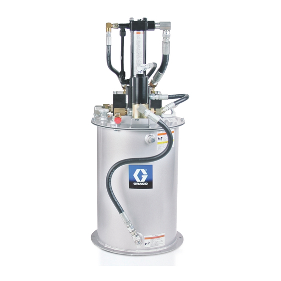
5:1 Dynastarr Pump Module
Part No. 243159, Series C
Part No. 243502 (35# Custom Tank Installation)
Part No. 243503 (120# Custom Tank Installation)
Part No. 243504 (400# Custom Tank Installation)
3500 psi (24 MPa, 240 bar) Maximum Lubricant Outlet Pressure
3500 psi (24 MPa, 240 bar) Maximum Hydraulic Fluid Input Pressure
Hydraulic Vent Valve Kit Part No. 243170
Hydraulic Control Module Kit Part No. 243501
GRACO INC. P.O. BOX 1441 MINNEAPOLIS, MN 55440–1441
ECOPYRIGHT 1999, GRACO INC.
Graco Inc. is registered to I.S. EN ISO 9001
309098F
First choice when
quality counts.t
Part No. 243159
ENG
Advertisement
Table of Contents

Related Manuals for Graco Dynastar 243159


Summary of Contents for Graco Dynastar 243159
- Page 1 3500 psi (24 MPa, 240 bar) Maximum Hydraulic Fluid Input Pressure Hydraulic Vent Valve Kit Part No. 243170 Hydraulic Control Module Kit Part No. 243501 Part No. 243159 GRACO INC. P.O. BOX 1441 MINNEAPOLIS, MN 55440–1441 ECOPYRIGHT 1999, GRACO INC. Graco Inc. is registered to I.S. EN ISO 9001...
- Page 2 D Read all instruction manuals, tags, and labels before you operate this equipment. D Use the equipment only for its intended purpose. If you are not sure, call your Graco distributor. D Do not alter or modify this equipment. Use only Graco approved repair parts.
- Page 3 WARNING INJECTION HAZARD Fluid from the dispensing valve, leaks or ruptured components can inject fluid into your body and cause extremely serious injury, including the need for amputation. Fluid splashed in the eyes or on the skin can also cause serious injury. D Fluid injected into the skin might look like just a cut, but it is a serious injury.
- Page 4 The Dynastarr pump module was carefully packaged 3. Compare the packing slip against all items in- for shipment by Graco. When the package arrives, cluded in the box. Any shortages or other inspec- perform the following procedure to unpack the units: tion problems should be reported immediately.
-
Page 5: Installation
Installation Reservoir Mount reservoir [Fig. 2, item (P)] on sturdy flat surface with 6, 3/8 in. diameter bolts. Note location of fill port (K), hydraulic lines, and lubricant outlet port (G) for easy access once installed. WARNING Hydraulic system must depressurized before connecting high pressure hydraulic supply line. - Page 6 Installation Typical Installation The installation shown in Figs. 2, 4, and 5 are only a guide for selecting and installing system components. Contact your Graco distributor for assistance in planning a system to suit your needs. Controller Capabilities Low Reservoir...
- Page 7 Vent Valve Installation Kit (243170) Hydraulic control line Vent valve Pump output connection line Pressure relief valve Lubricant output Vent line 9647A Fig. 3 Control Module Installation Kit (243501) Pump tank line Pump high pressure hydraulic line Vent valve hydraulic control Hydraulic tank connection High pressure hydraulic connection Pressure reducing valve...
- Page 8 Installation Vent return port 1/2” npt (f) Pump mounting ∅ .343 or 5/16–18 (4X) Vent valve bracket weld locations Control module ∅ .343 or 5/16–18 (2X) 18.0 Max 3.536 6.875 3.536 9653A Fig. 5 309098...
-
Page 9: Operation
Operation Pressure Relief Procedure Fill Reservoir 1. Connect lubricant supply hose from remote filling WARNING station pump to fill port (Fig. 2, item K). 2. Connect automatic lube system main supply INJECTION HAZARD line (G) to vent valve (U) outlet. To reduce the risk of serious injury, in- cluding fluid injection or splashing in the 3. -
Page 10: Troubleshooting
Operation Shut Down. CAUTION 1. For normal system shut down, disconnect power Never allow the pump to run dry of the fluid being to lubricator controller (J) by turning off the ignition pumped. A dry pump will quickly accelerate to a high switch, and turn off hydraulic supply by closing the speed, possibly damaging pump. -
Page 11: Parts Drawing
Parts Drawing Pump hydraulic outlet Pump lubricant outlet Pump hydraulic inlet 9652B 309098... - Page 12 Parts Drawing To pump hydraulic inlet To pump hydraulic outlet To pump lubricant outlet Item 4a: Torque to 40–43 ft lbs (54–58 Nm) (lubricate o–ring with oil before installation) Item 4c: Torque to 15–20 ft lbs (20–27 Nm) (lubricate o–ring with oil before installation) Item 4d: Torque to 20–25 ft lbs (27–34 Nm) (lubricate o–ring with oil before installation) Item 4e: Torque to 15–20 ft lbs (20–27 Nm) (lubricate o–ring with oil before installation) Item 4f: Torque to 68–75 ft lbs (92–102 Nm) (lubricate o–ring with oil before installation)
-
Page 13: Parts List
Parts List Model 243159, Dynastar Pump Module includes items 1 – 8 *Model 243502, 35# Dynastar Pump Module Installation Kit includes items 1, 2, 4 and 8 *Model 243503, 120# Dynastar Pump Module Installation Kit includes items 1, 2, 4 and 8 *Model 243504, 400# Dynastar Pump Module Installation Kit includes items 1, 2, 4... -
Page 14: Technical Data
Technical Data Maximum hydraulic input pressure ..........3500 psi (241 bar, 24 MPa Pump wetted parts . - Page 15 Hydraulic Control Module Circuit: 243501 Does not include pump and pump valve kit. 309098...
-
Page 16: Graco Standard Warranty
Graco distributor to the original purchaser for use. With the exception of any special, extended, or limited warranty published by Graco, Graco will, for a period of twelve months from the date of sale, repair or replace any part of the equipment determined by Graco to be defective.
Need help?
Do you have a question about the Dynastar 243159 and is the answer not in the manual?
Questions and answers