Table of Contents
Advertisement
Advertisement
Table of Contents

Related Manuals for HP 3400B


Summary of Contents for HP 3400B
- Page 2 Buyer shall prepay • are issued between other legal theory. shipping charges to HP editions, may motain Safety Symbo and HP shan pay shipping Notice additional information and charges to return the replacement pages which The information contained product to the Buyer.
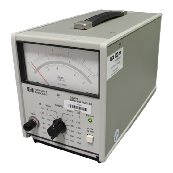
- Page 3 • The HP 3400B is a true roo t · means· square (RMS) analog voltmeter • capable of measuring ac voltages from 100 microvolts to 300 volts. It is extremely flexible for audio and RF measurements from 10 and allows you to measure broadband noise and fast rise-time pulses.
- Page 4 The Front Panel at a Glance • VOLTS • meter (RMS volts Direct raadlng Input BNC connector screw • Zero adjusb'nent 4 Range selector switch (volts and dB) • �...
- Page 5 • The Rear Panel at a Glance • • CIltSl f.tl;TQR 10:1 fvl Scalf '" - Un. l00-240V 125m ... T • • Power-line lus&-holder assembly 3 DC output jack. Provides -1 Vdc output • Power-line voltage setting .t full-scale deflection; output Is proportional dellectlon;...
- Page 6 • Specifications ranges: 1 mV. 3 mY. 10 mV, 30 mV. lOOmV, 3OO m V, 1 mV to 300 mV 10 Mn ehunted • 1 V, 3 V. 10 V. 30 V. 100 V. 30 0 VfuI acaJe. by < 50 pF. �".,.. . ranges: MO shunted 300 V...
- Page 7 • Warnings and Cautions • Warning No user serviceable paris inside. Refer servicing trained • service personnel. Avertissement Ne contient pas d'eMment que l'uti.lisateur puisse nanc e a un technicien qualifW. reparer. Confier la mainte Warning For continued f.,.e protection, use specified fuse only. Avertiss e ment Pour maintenir la capacite de protection contre l'incendie, utilisez Ie fusible recommande seulement.
- Page 8 • In This Book • Quick Start Chapter prepares the voltmeter for use and helps you get familiar with its front· panel features. Chapter 2 provides a detailed description Calibration Procedures of the voltmeter's verification and adjustment procedures. Chapter 3 describes each functional block in Theory Operation the voltmeter.
-
Page 9: Table Of Contents
• Contents • • Chapter Quick Start To prepare the voltmeter for use To select the range T o use the D C output signal To rack mount the voltmeter Chapter Calihration Procedures Calibration Interval Time Required for Calibration • Recommended Test Equipment 20 Test Considerations 20 Operation Verification Procedures 21... - Page 10 03400-66522 Replaceable Parts: (Main Assembly) (Switch Assembly) 58 03400-66523 Replaceable Parts: 03400·66523 59 03400-66522 Manufacturer's Codes: Mainframe 60 340DB Replaceable Parts: HP Manufacturer's Codes: HP 340DB Mainframe Chapter Backdating Chapter Schematics • Mechanical Disassembly Component Locator Diagrams 68 Input Attenuator, Impedance Converter, and Power Supplies...
-
Page 11: Chapter 1 Quick Start
• • • • • • • • Quick Start... - Page 12 • Quick Start • • One of the first things you will want to do with your voltmeter is to become acquainted with its front panel. We have written the exercises in this chapter to prepare the voltmeter for use and help you get familiar with some of its front·panel operations.
-
Page 13: To Prepare The Voltmeter For Use 1
Chapter • Quick Start To prepare the voltmeter f o r u se To prepare the voltmeter for use • The f ollowing steps help you verify that the voltmeter is ready for use. Check the list of supplied items. Verify that you have received the following items with your voltmeter. - Page 14 • Start Chapter Quick tor use To prepare the voltmeter 1 Remove the fuse-holder assembly from 2 Remove the line-voltage selector from rear panel. the assembly..• ....
-
Page 15: To Select The Range
• Chapter Quick Start To select the range To select the range • You can make measurements using one of voltage ranges available. The voltmeter is capable of measuring true·RMS ac voltages from 100 IlV to 300 V. When measuring an ac signal superimposed on a level, you should Cau t ion always set the range selector switch to the 300 volt position. -
Page 16: To Use The Dc Output Signal
On the 3's ranges (0.003, 0.03, 0.3, 3, etc.), the full· scale output is -0.9487 Vdc. A plwne plug for the DC output jack is available by orderiTllf HP part number 1251·0067. ACC lJIt'C I � rull xalt © CllE SI f.t.C1011 """ 1 IIf'[IWfC£... -
Page 17: To Rack Mount The Voltmeter
Chapter Quick Start rack mount the v oltmeter To rack mount the voltmeter • You can mount the voltmeter in a standard 19-inch rack cabinet using one of two optional kits available. If your application requires that you frequently remove the voltmeter from the cabinet. the combining case is recommended. - Page 18 To rack mount the voltmeter • � • -• • ..• .• @::.to 1052A 5060-8741. To use the combining case, order part number HP and rack mount • '" -� . • • (;) . " .." •...
- Page 19 • • • • • • Calibration Procedures...
- Page 20 Calibration Procedures • • This chapter contains procedures for performing the voltmeter's verification and adjustment procedures. Notice that the verification divided into two levels: Operation V erification (verifies procedures that the voltmeter meets selected testable specifi ca tions) and Performance V erification (verifies that the voltmeter meet testable specifications).
-
Page 21: Chapter 2 Calihration Procedures
This will increase your confidence that the HP 3400B will remain within specification for the next calibration interval. This criteria for re.adjustment provides the best measure of the voltmeter's long·term stability. Performance data measured using this method can easily be used to extend future calibration intervals. -
Page 22: Recommended Test Equipment
HP 8161A Pulse Generator, HP Multimetar Check OVerload Protection Circullry Fluke 5700A caJibrator, HP 3458A Multimetar Crest Factor Check (page HP 8161A Pulse Generator, HP 3458A Multimetar Front-Panel Melar Zero Adjuslment (page 28) None • Scale Full GaIn Adjuslment (page 29) -
Page 23: Operation Verification Procedures
20 MHz -1.05 V to �.95 V • HP 3400B: Select the 1 volt range. Calibrator: Select a 1 volt ac signal at 10 Hz (use the "Wideband" output on the Fluke 5700A). External Multimeter: Select the 10 Vdc range with 5\.2 digits of •... -
Page 24: Performance Verification Procedures
Chapter 2 Calibration Procedures Performa nce Verification Proced ures • Performance Verification Procedures • The procedures in this section used test the voltmeter's electrical performance using the specifications given on page 4 as the performance standard. You can use these tests for incoming inspection, periodic maintenance, and specification checks after a repair. - Page 25 Chapter 2 Calibration Procedures Performance Verification Procedures un Scale Test 1 HP 3400B: 0.001 Select the volt range. • 0.001 10 Hz. Calibrator: Select a volt ac signal at External Multimeter: Select the Vdc range with 5\;2 digits of resolution.
- Page 26 Continue checking the de output as you adjust the calibrator's output voltage and frequency to each of the remaining values shown in the table below. • HP 3400B calibrator calibrator DC Output Range Output Vo�...
- Page 27 -1 jack. This voltage is normalized Vde and is proportional input voltage Vde corresponds a full-scale meter deflection). HP 3-100 8 Source DC OUtput Source Range Ou1put Voltage Output Frequency (DMM Reading) 0 .
- Page 28 + 1 .0 V to + 5.0 V -60 V to 1 0 V 1 HP 3400B: Select the 0.1 volt range. 1 kHz Calibrator: Select a 0.1 volt ac signal at (use the low frequency output on the Fluke 5700A).
- Page 29 -1 . 0 5 Pulse Ou1put Wldth.1 mSec. Frequoncy=10 Hz. Modo=Pu!se • 1 HP 3400B: Select the volt range. 2 Source: Program the source to output a pulse train with the following characteristics: Vout= 1. 5 volta, offset=750 m V, •...
-
Page 30: Adjustment Procedures
calibration Chapter 2 Procedures Adj us tment Proced ures Adjustment Procedures • used to adjust the voltmeter for peak The procedures in this section performance. For best performance, the voltmeter should always be adjusted after repair. not perform the adjustment procedures unless they required. - Page 31 • Chapter 2 Calibration Procedures Adj ustment Proced ures • Full Scale Gain Adjustment This procedure manually adjusts the voltmeter for full scale readings. • The full scale adjustment and the tenth scale adjustment (described in the next section) interdependent and you should repeat the adjustments until both measurements within the recommended limits.
- Page 32 Ext ernal Multimet er: Select the 10 Vdc range with 5� digi ts o C resolu tion. • Remove only the top cove r from the HP 34008 (it is important R32l tha t you do rwt remove the side or bottom cove rs). Adju st until the dc voltage mea sured at the rea r-panel dc output jack is within the limits shown in the table above.
- Page 33 (DMM Reacing) • 0.0 1 V 1 kHz O . OO t -o . 1 HP 3400B: Select the 0.01 volt range. I kHz Calibrator: Select a 0.001 volt ae signal at (use the • "Wideband" output on the Fluke 5700A).
- Page 34 5700A). ·Wideband" output on the Fluke • Allow one minute for the meter pointer to stabilize. • 4 Remove the top cover from the HP 3400B only (it is important that you do rwt remove the side or bottom covers). Adjust...
- Page 35 -1 . 0 125 V to -0 . 9875 • t HP 3400B: Select the 0. 1 volt range. Calibrator: Select a 0. 1 volt ac signal at 20 MHz (use the "Wideband" output on the Fluke 5700A). • 3 External Multimeter: Select the 10 Vdc range with 51.<.! digits of resolution.
- Page 36 • Chapter 2 Calibration Procedures Adj ustment Proced ures • Input Attenuator AdjustIDent (see This procedure performs a manual adjustment of the input attenuator • First, will at 50 and 100 kHz. make the low frequency adjustment at 3V150 (see using Rl23 on the main circuit board will make the high frequency adjustment at 3V1100 kHz...
- Page 37 Exte rna l Multime ter: Select the 10 Vdc range with 51'.! digits of resolution. Remove only the right-side cover fr om the HP 3400B (as viewed from the front pane l). It is important that you do rwt remove the Rl23 left-side, top, or bottom covers.
-
Page 38: Test Connector Pinout
• Chapter 2 Calibration Procedures Test Connector Pinout Test Connector Pinout • Test connector J3 gives you access to several test points on the main circuit board. You can build your own custom ribbon cable interface convenient for your application. The table below shows the pinout for the test connector. -
Page 39: Chapter 3 Theory Of Operation
• • • • • • • ---- Theory of • Operation... -
Page 40: Block Diagram
• Theory of Operation • • This chapter is organized to provide descriptions of the circuitry contained on each schematic shown in chapter 7. A block diagram overview is provided f ollowed by more detailed descriptions of the circuitry contained in the schematics chapter. •... - Page 41 Chapter Theory of Operation Block Diagram Block Diagram • Ref erring to the instrument block diagram shown below, you can that the voltmeter's operational circuitry consists of two attenuators, an impedance converter, a wideband amplifi e r, a chopper op amp, a thermocouple pair, and a direct reading meter.
- Page 42 Chapter Theory Operation Block Diagram • A signal being measured applied to the input attenuator through the Input connector, located on the voltmeter's front panel. The input • attenuator has an input impedance of 10 Mn and provides two ranges of attenuation.
-
Page 43: Input Attenuator 4
Chapter Theory of Operation Input Attenuator Input Attenuator • The input attenuator is a capacitive-compensated attenuator which provides two ranges of attenuation for the 1 2 positions of the Range selector switch. When the selector switch is positioned to one of the six most sensitive ranges (1 m V to 300 m V), the attenuator output voltage is equal to the input voltage. -
Page 44: Post Attenuator
� . The wideband amplifier provides constant gain to the ac signal being measured over the entire frequency range of the HP 3400B. The wideband amplification required to drive the thermocouple heater is provided in two gain stages. The first stage has a gain of 36 dB and consists of a differential transistor pair Q301 and Q302 driving U301. -
Page 45: Chopper Op Amp I Thermocouple Pair
Operation Chapter Theory of Chopper Op Amp Thermocouple Pair Chopper Op Amp Thermocouple Pair • The chopper op amp and the thermocouple pair form a servo loop which functions to position the direct reading meter (Ml) to the RMS value of the ac input signal. -
Page 46: Power Supplies
Chapter Operation Power Supplies Theory of . � Power Supplies • • The power supplies provide de operating voltages for the circui try used in the 3400 8 . The input line power is applied to an input line module. The module contains a line filter, a fuse, the line switch, and voltage t ap selection for the power transformer. -
Page 47: Switch Board
Chapter Theory of Operation Switch Board Switch Board • The switch control cireuitry is located on the small circuit board which (see is connected to the front· panel Range selector switch. The Schottky board diodes (CR4I through CR60) on the switch provide the appropriate relay logic for the relay drivers on the main circuit board table... -
Page 48: Chapter 4 Service
• • • • • • Service... -
Page 49: Operating Checklist
Service • This chapter discusses the procedures involved for returning a failed voltmeter to Hewlett-Packard for service or repair. Subjects covered include the f ollowing: • Operating Checklist 49 • To Replace the Power-Line Fuse 49 • Repackaging for Shipment 50 •... - Page 50 (see page 12). A 125 mAT slow-blow fuse (HP part number 2 1 10-0894) is installed when the voltmeter is shipped - from the factory. This is the oorrect power-line fuse for 100, 120 220, or 240 Vac operation .
-
Page 51: Repackaging For Shipment
Repackaging for Shipment Repackaging for Shipment • If the instrument is to be shipped to HP for service or repair, be sure to: • Attach a tag to the voltmeter identifying the owner and indicating the required service or repair. Include the instrument model number and full serial number. -
Page 52: Chapter 6 Replaceable Parts
• • • • • • • Replaceable Parts... -
Page 53: To Order Replaceable Parts
• manufacturer using the manufacturer's part number in the replaceable parts list. To order replaceable parts from HP, do the following: Contact your nearest HP Sales Office or Service Center. Identify parts by their HP part number shown in the replaceable •... - Page 54 Chapter Replaceable Parts • Replaceable Parts: 03400·66522 - Main PC Assembly • HP Part Mfr. Number Part Deocrlpllon Codo Mfr. Part Number t 20% A1Cl0l 0180-3925 C8pacltor·Fxd 470 uF 100 V 28480 0180-3925 C8pacltor·Fxd 1 uF 56289 1730105X9035V A1Cl02 0180-4129...
-
Page 55: Replaceable Parts: 03400-66522
Chapter Replaceable Parts HP Part Reference Mfr. Code Designation Number Part Description Mfr. Part Number +80% - 04222 A1 C320 016().4844 capacilor-Fxd 1 uF 50 V SA305El0SZAA 04222 016().4835 A1 C321 capacllor-Fxd 0.1 uF ± 1 0% 50 V SA105C104KAAH... - Page 56 Replaceable Parts Chapter Replaceable Parts (continued) HP Part Mfr. Code Part Description Number Mfr. Part Number Resistor 249 ± 1% .125W TC- O±loo A1Rl0l 0698-442 1 24546 CT 4-11&-TO-249R·F A1Rl02 0757-G138 Resistor 5.11 K ± 1% .125W TC- O±loo CT 4-11&-TQ-51 11·F...
- Page 57 Chapter Replaceable Parts Retere""" HP Part Mfr. Designation Number Part Description Code Mfr. Part Number 0±'25 A1R216 0698-6323 Resis1Dr 100 ± 0.1 % .1 '25W TF TC 0698-6323 28480 0±'25 • A1R217 0698-6n4 Resis1Dr 150 ± 0.1 % .1 '25W TF TC...
- Page 58 Chapter Replaceable Parts �22 Replaceable Parts (continued) HP Part Mfr. Part DeocrIption Number Coda Mfr. Part Number A1 R339 0757-044 6 Resis1Dr 15K± 1 % .125WTF TC _ 0±100 CT4-118-TO-1502-F 2� A1 R340 0757-()410 Resis1Dr 301 ± 1% .125W TF TC _ 0±100...
-
Page 59: Replaceable Parts: 03400-66523
Chapter Replaceable Parts • Replaceable Parts: 03400·66523 Switch PC Assembly • Reference HP Part Mfr. Number Designation Part Description Code Mfr. Part Number 5008 8 SIgnal A2CR341-CR3eO 1� DIode-Schol1ky Small lN5711 A2Pl 03400-6 1 607 SWitch Cable 28480 03400-6 1 607... -
Page 60: Manufacturer's Codes: 03400-66522
Chapter Replaceable Parts • • Manufacturer's Codes: 03400-66522 and 03400-66523 Manufacturer's Name Manufacturer's Addr e ss ZJp Codo 00779 AMP Inc Harrisburg, PA U.S.A. 171 1 1 01121 Allen-Bradley Co Inc EI Paso, U.S.A. 79935 03888 Corp KDI Pyrofilm Whippany, NJ U.S.A. 07981 0Q22 Greal Neck, NY U.S.A. - Page 61 Chapter Replaceable Parts Replaceable Parts: HP 3400B Mainframe • • Reference HP Part Mfr. Designation Number Part Description Coda Mfr. Part Number 034()().900 1 4 English Manual (UserlService Guide) 28480 034()().900 1 4 1 120-0308 Metsr Mechanism - dB Scale (Opt 001 only)
- Page 62 • Chapter Replaceable Parts 3400 8 Mainframe ReplK8ll b le Parts (continued) HP Part Mfr. Number Part Deacription Mfr. Part Number Code 5041-0564 Pushbutton · Power-On Push Rod 2&480 5041-0564 030l00-0 020 5 Instrument Panel · Front PNL1 2&480 034()().O()2() S...
-
Page 63: Manufacturer's Codes: Hp
• Chapter Replaceable Parts • Manufacturer's Codes: HP 3400B Mainframe • • Mfr. Code Code ManufacbJrer's Name Manufacb,ner's Adci'ess AMP Inc Harrisbu r g, PA U.S.A. 171 1 1 00779 05275 ITT Pomona Electronics Pomona, CA U.S.A. 91766 06090 Menlo... -
Page 64: Chapter 6 Backdating
• • • • • • • • Backdating... - Page 65 • Backdating • • this This chapter rwrmally contains inf ormalUJn necessary to adnpt manual to instruments rwt dire£tly covered by the current content. At this printing, however, the manual does apply to all instruments. this 1'h£ref ore, rw inf ormation incUuled in chapter.
-
Page 66: Chapter 7 Schematics
• • • • • • • • Schematics... -
Page 67: Mechanical Disassembly Component Locator Diagrams
• Schematics • • • Mechanical Disassembly • Component Locator Diagrams 68 • Input Attenuator, Impedance Converter, and Power Supplies • Relay Drivers and Post Attenuator • Wideband Amplifier, Chopper Op Amp, and Overload Detector • Switch Board Schematic • •... - Page 68 Rl07 � 0 0 0 ° oumDa � CXlO4 � o g • o D!ll[J o ocm![]a (321 UJJ I oDm[]a oOl!lH]a !DOl a 0 []!Ji[J a g ill � o O @]o � 0 om:J om:J 0 !lID oCii!iIl a 1326 �...
- Page 69 >. r- "- � :0 <0 ::;: .."- '" ::;: '" '" '" > "- •...
- Page 70 5t<IElD ----------------------------------- IMPEDENCE CONVERTER " INPUT AITENUATOR " • CL�I " • / . 1 '" �. • Dill CI" "" '" (Ill ) • _Ill Y!� 1.1'" • • " tlUI 'lOl.ul OIL!' IS.' " � � am ",. �15V tII lll ·...
- Page 71 IIIM ' ''(A� " (I�I'" � (I � R[lIlY RELAY [t£RGllED DE -(t.[RGllEO � 1Il111 � .'011 voc.rs itO\ K21)\ 1<202 K20. K20) • oQO'_ UZ'I( .001 """n.> • .(0) � . ( 1 1) .0)0 . 1 00 . 3 0 0 GHll I 000 3 000...
- Page 72 • "1!. '18 OVERLOAD OETECTOR n,· . • • • • " " r" '" '" ·.Il' • t'l� '"' WI DEBAND AMPl l r IE� (R1Gl • • " ..w • � : :: I : " " -:- l lll IS._ .
- Page 73 • • K l 0 l K2 0 1 K202 , K204 K203 • "- MOUNT I NG BRACKET FOR C> S�-COM C> C> REAR-DC REAR-DC, C> TP I O METER 11 METER "- SHLD4t2 0... " lPI2 I ) LED TPI4 JHP02 165 SW-COM...
-
Page 74: Index
5 c ecklist HP 3458A items included, 1 1 needle adjustment. 28. 32 Multimeter, 20 HP SI61A Pul operating, 49 chopper qJ amp description, 43 .. Generator. 20 needle adjustment. full scale. 32 ooefficient, temperature, 4 •... - Page 75 Index • • rack adapter frame, 16 voltage range selection, 13 oft8et, zero, 4, 13 voltage range swikh. 2, 13 operation verifi c ation pl'OCedures, 21 rack mounting operating checklist, 49 adapter frame, 16 voltage, power-line case, changing, 12 output jack, rear-panel, 3, 1 4 combining factory setting, I I overload protection check, 26...
- Page 76 • Declaration of Conformity According to ISO/lEG Guide 22 aIId EN 45014 Hewlett·Packard Company declares that the HP 34008 V oltmeter conf orms to the following Product Specifications. (1990 ) Safety: IEC 1010· 1 CSA 231 1244 CISPR 1 1: 1990IEN5501 1 (1991): Group 1 Class A EMC: IEC 801·2: 1991IEN500 8 2·1 (1992): 4 kV CD, 8 kV...
- Page 77 Contents • The Front Panel at a Glance 2 • The Rear Panel at a Glance 3 Specifications 4 In This Boo k 5 Quick Start 9 Chapter 1 Chapter 2 Calibration Procedures 1 7 Chapter 3 Theory of Operation 37 •...
Need help?
Do you have a question about the 3400B and is the answer not in the manual?
Questions and answers