
Subscribe to Our Youtube Channel
Related Manuals for Tektronix MultiPaq VX4101A


Summary of Contents for Tektronix MultiPaq VX4101A
- Page 1 (217) 352-9330 | Click HERE Find the Tektronix VX4101A at our website:...
- Page 2 User Manual VX4101A MultiPaq Instrument 071-0049-01 This document supports firmware version 2.0 Warning The servicing instructions are for use by qualified personnel only. To avoid personal injury, do not perform any servicing unless you are qualified to do so. Refer to the Safety Summary prior to performing service.
- Page 3 Commercial Computer Software – Restricted Rights clause at FAR 52.227-19, as applicable. Tektronix products are covered by U.S. and foreign patents, issued and pending. Information in this publication supercedes that in all previously published material. Specifications and price change privileges reserved.
- Page 4 Tektronix, with shipping charges prepaid. Tektronix shall pay for the return of the product to Customer if the shipment is to a location within the country in which the Tektronix service center is located.
- Page 5 Artisan Technology Group - Quality Instrumentation ... Guaranteed | (888) 88-SOURCE | www.artisantg.com...
-
Page 6: Table Of Contents
Table of Contents General Safety Summary ........Service Safety Summary . - Page 7 Table of Contents Measuring Frequency ..........2–27 Measuring Time Interval .
- Page 8 Table of Contents CONFigure Subsystem ..........3–63 FETCh? Subsystem .
- Page 9 Table of Contents CALCulate Subsystem ..........3–202 CALibrate Subsystem .
- Page 10 Table of Contents STATus : QUEStionable : CONDition? ....... . 4–16 STATus : QUEStionable : ENABle .
- Page 11 Table of Contents List of Figures Figure 1–1: VX4101A VXIbus Connectors, Fuses, and Switch Locations ........1–7 Figure 1–2: VX4101A Front Panel .
- Page 12 Table of Contents List of Tables Table 1–1: VX4101A Performance Options ..... 1–2 Table 1–2: Standard Accessories ......1–12 Table 1–3: Optional Accessories .
- Page 13 Table of Contents Table 4–2: VX4101 A Operational Status Register ....4–5 Table 4–3: Status Byte Register ....... 4–6 Table 4–4: IEEE 488.2 Standard Event Status Register .
- Page 14 Table of Contents Table A–35: Accuracy Specifications for 2-Second Aperture ..A–14 Table A–36: Accuracy Specification for v 1 Millisecond Aperture A–15 Table A–37: DC Input Resistance ......A–16 Table A–38: DC Input Protection .
- Page 15 Table of Contents VX4101A MultiPaq Instrument User Manual Artisan Technology Group - Quality Instrumentation ... Guaranteed | (888) 88-SOURCE | www.artisantg.com...
-
Page 16: General Safety Summary
General Safety Summary Review the following safety precautions to avoid injury and prevent damage to this product or any products connected to it. To avoid potential hazards, use this product only as specified. Only qualified personnel should perform service procedures. While using this product, you may need to access other parts of the system. - Page 17 General Safety Summary Symbols and Terms Terms in this Manual. These terms may appear in this manual: WARNING. Warning statements identify conditions or practices that could result in injury or loss of life. CAUTION. Caution statements identify conditions or practices that could result in damage to this product or other property.
-
Page 18: Service Safety Summary
Service Safety Summary Only qualified personnel should perform service procedures. Read this Service Safety Summary and the General Safety Summary before performing any service procedures. Do Not Service Alone. Do not perform internal service or adjustments of this product unless another person capable of rendering first aid and resuscitation is present. - Page 19 Service Safety Summary VX4101A MultiPaq Instrument User Manual Artisan Technology Group - Quality Instrumentation ... Guaranteed | (888) 88-SOURCE | www.artisantg.com...
-
Page 20: Preface
Preface This manual assumes you are familiar with the operation of VXIbus instruments and with the purpose and function of this instrument. Please read and follow all instructions for installation and configuration. Use the Installation Checklist to ensure proper installation and to record your initial settings. - Page 21 Preface VX4101A MultiPaq Instrument User Manual Artisan Technology Group - Quality Instrumentation ... Guaranteed | (888) 88-SOURCE | www.artisantg.com...
-
Page 22: Getting Started
Getting Started Artisan Technology Group - Quality Instrumentation ... Guaranteed | (888) 88-SOURCE | www.artisantg.com... - Page 23 Artisan Technology Group - Quality Instrumentation ... Guaranteed | (888) 88-SOURCE | www.artisantg.com...
-
Page 24: Product Description
Digital Input and Output Full function Digital Multimeter (DMM) Digital to Analog Converter (DAC) Relay Drivers Scanner master function for the Tektronix SurePath family of VXI relay modules Features All instruments included in the VX4101A are VXI message-based. Each function is located at the same logical address, but can be accessed and used separately. -
Page 25: Table 1-1: Vx4101A Performance Options
Product Description The VX4101A is programmed by issuing ASCII characters from the system controller via the VXIbus commander and the VXIbus mainframe backplane. Refer to the manual for the VXIbus device that will be the commander for details on the operation of that device. Instrument Control. - Page 26 Product Description Measurement gating comes from one of several sources, including VXI TTL triggers, counter front panel arm, software triggers, periodic trigger, and another VX4101A instrument, such as SurePath relay switched and settled. Other key features of the Universal Counter are as follows: Frequency measurements with ten-digit resolution at 1 second aperture, with a range of 1 Hz - 250 MHz The option 1C extends the maximum frequency beyond 500 MHz...
- Page 27 Product Description Digital Input. The Digital Input has a single programmable voltage threshold for all 32 bits. The range of the input threshold voltage is from 0 volts to 20 volts. The Digital Input has 8 K samples of digital input memory, 4 K samples each for the pre-match pattern buffer and the post-match memory.
- Page 28 About the SurePath The scanner master control enables you to use the VX4101A to control the Modules Tektronix SurePath family of VXI relay modules, including the VX4320, VX4330, VX4350, VX4351, and VX4380. Some of the features of the Sur- ePath family are as follows: VX4320 1.3 GHz RF Multiplexor.
- Page 29 Product Description programmed to connect it to the section above or below to produce a 1 4-wire multiplexor, a 1 120 2-wire multiplexor, or a 1 240 1-wire multiplex- VX4350 64-Channel SPST/SPDT Switching Module. This module provides 64 independent single-pole double-throw relays. A 0 resistor is placed in series with the common contact of each relay.
-
Page 30: Power-On Sequence
Product Description Power-On Sequence The power-on sequence of the VX4101A meets the timing requirements of the VXIbus specification that communications may begin even if the instrument has not completely initialized. At either power-on or a VXIbus reset, the VX4101A initializes the VXIbus interface and all hardware and firmware necessary to begin communication. -
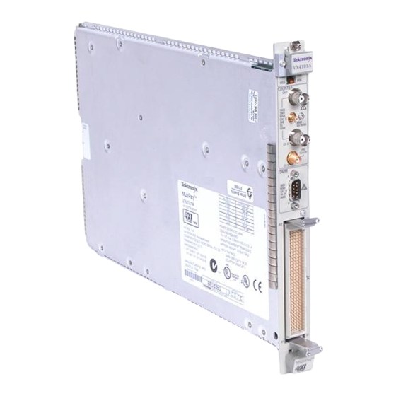
Page 31: Figure 1-2: Vx4101A Front Panel
Product Description Figure 1–2: VX4101A Front Panel Controls and Indicators The following logical address switches must be correctly set to ensure proper operation. Refer to Figure 1–1 for their physical locations. Logical Address Switches. The VX4101A supports VXI dynamic addressing. It is shipped with the switches set to FF so that the Slot 0 will automatically assign an address to the module. - Page 32 Product Description NOTE. If you do not want to use dynamic addressing, align the desired switch position with the arrow on the module shield. The physical address of the instrument is on a 64 byte boundary. If the Logical Address switch representing the most significant digit (LA-HI) of the logical address is set to position X and the switch representing the least significant digit (LA-LO) of the logical address is set to position Y, then the base physical address of the module will be [(40...
-
Page 33: Fuses
Product Description Fuses The VX4101A has 6 fuses that limit the amount of current that each module can draw from the VXI backplane +5, -5.2, +24, -24, +12, and -12 V power pins. These fuses protect the module in case of an accidental shorting of the power bus or any other situation where excessive current might be drawn. - Page 34 Product Description Counter Self-Test The self-test for the Counter tests the following components: The two 4 Kb Counter measurement buffers. Logic registers The analog front end pre-amp offset, pre-amp inverter, and pre-amp gain digital to analog converters (DACs). A 2.5 MHz signal is routed in through a test source and checked for accuracy.
-
Page 35: Accessories
Product Description Accessories The following tables list the standard and optional accessories for the VX4101A: Table 1–2: Standard Accessories Tektronix part Mfr. number Name and description Mfr. Code part number VX1784S CONN HOODED; DE–9 FEMALE SOCKET TK2548 071–0049–XX MANUAL,TECH:USERS,VX4101A TK2548 071–0049–XX... -
Page 36: Performance Options
Product Description Performance Options You can purchase the following options to enhance performance of the VX4101A: Table 1–4: VX4101A Performance Options Description Option Number 500 MHz Counter Channel One and Channel Two 3 GHz Counter prescaler Channel Three Eight Channel DAC 32 Bit Digital I/O with Eight Relay Drivers TCXO... - Page 37 Product Description Using the VXI plug&play Double clicking on the appropriate instrument icon launches the soft front panel Software (SFP). The SFP displays a representation of the traditional controls and indicators for an instrument. By selecting the appropriate controls on the SFP, you can verify that the instrument has been correctly installed and is functional, and perform almost all of the functions of the instrument.
-
Page 38: Installation
At the end of the section, you will find a checklist to summarize your installation choices. Installing the Module in the Mainframe Installing the VX4101A in a Tektronix mainframe meets all instrument cooling requirements. Tools Required A slotted screwdriver set is required for proper installation. -
Page 39: Figure 1-3: Module Installation
If the jumpers are not installed properly, there will be no interrupts and bus masters will not operate properly. Jumpers are not necessary for auto-configuring backplane designs such as those in Tektronix mainframes. Module Installation Follow these steps to install the VX4101A: Procedure CAUTION. -
Page 40: Installing The Vxiplug&Play Software
About the Device Drivers The device driver distributed with the Tektronix VX4101A complies with all current VXIplug&play requirements. The device driver uses VISA calls that are portable across platforms and development environments. Tektronix uses only the ANSI C implementation in instrument driver source code. -
Page 41: Table 1-5: Instrument-Specific Files
Installation 3. Launch setup.exe as follows: In Windows or Windows NT/3.x, use the File menu and select Run. Then, browse to find setup.exe or type the drive letter and program name In Windows 95 or or Windows NT/4.x, use Start and select Run. Browse to locate setup.exe and click on OK 4. - Page 42 Installation tkvx4101.hlp tksf4101.exe Supporting driver files will be located in the following directories: VXIPNP\<Framework>\support\tkmpdmm: tkmpdmm.c tkmpdmm.fp tkmpdmm.mak tkmpdmm.def tkmpdmm.hlp VXIPNP\<Framework>\support\tkmpctr: tkmpctr.c tkmpctr.fp tkmpctr.mak tkmpctr.def tkmpctr.hlp VXIPNP\<Framework>\support\tkmpscan: tkmpscan.c tkmpscan.fp tkmpscan.mak tkmpscan.def tkmpscan.hlp VXIPNP\<Framework>\support\tkmpdac: tkmpdac.c tkmpsdac.fp tkmpdac.mak tkmpdac.def tkmpdac.hlp VXIPNP\<Framework>\support\tkmpdigo: tkmpdigo.c tkmpdigo.fp tkmpdigo.mak tkmpdigo.def tkmpdigo.hlp...
- Page 43 Installation tkmpdigi.def tkmpdigi.hlp VXIPNP\<Framework>\support\tkmprdrv: tkmprdrv.c tkmprdrv.fp tkmprdrv.mak tkmprdrv.def tkmprdrv.hlp VXIPNP\<Framework>\support\tkfdc: tkfdc.c tkfdc.fp tkfdc.mak tkfdc.def tkfdc.hlp The directories listed above contain several *.uir (User Interface Resource) files that support the GUI executables (CVI files). The following files are installed in the VXIPNP\<Framework>\INCLUDE directory: tkvx4101.h tkmpdac.h...
- Page 44 .DLL file with the modifications. NOTE. Tektronix recommends that you back up your original source files before modifying the driver files CAUTION. The Soft Front Panel (SFP) distributed with this driver is built using the distributed .DLL files.
-
Page 45: Powering-On The Vx4101A
Installation Powering-On the VX4101A The VX4101A instrument runs its interface test and is ready for communication within five seconds. The VXIbus Resource Manager can add an additional delay. The Power LED will be on. The Failed LED will be off. The default condition of the module after power-on is listed in the *RST command description. - Page 46 Installation Table 1–6: Commands Available at Power-On (Cont.) Command Syntax Command Type Description *SRE? IEEE 488.2 Queries the contents of the IEEE 488.2 Service Request Enable Register. *STB? IEEE 488.2 Queries the contents of the IEEE 488.2 Status Byte Register. STATus:OPERation:CONDition? Status and Events Returns the current operational...
- Page 47 Installation Table 1–6: Commands Available at Power-On (Cont.) Command Syntax Command Type Description STATus:QUEStionable:ENABle? Status and Event Queries the Questionable Enable Reporting System Register for the VX4101A STATus:QUEStionable:PTRansi- Status and Event Sets the Questionable Positive tion Reporting System Transition Filter for the VX4101A STATus:QUEStionable:PTRansi- Status and Event Queries the Questionable Positive...
-
Page 48: Sysfail* Operation
Installation The format and syntax for the command strings are described in the Command Syntax section. A complete description if each command in alphabetical order is in the Command Descriptions section. Using VXIplug&play Device Drivers. If you are using instrument drivers to control the VX4101A, instrument initialization occurs automatically. -
Page 49: Operational Check
Installation 488.2 commands can be used to run more extensive self-tests of instrument specific functions. During the interface test, or during a hard or soft reset, the following actions take place: 1. The backplane SYSFAIL* line is asserted, indicating that the module is not ready for communication. - Page 50 Operational Check for To perform the operational check, do the following: Standard Configuration 1. Double click on the TKVX4101A icon to start the SFP. The Tektronix VX4101A MultiPaq SFP displays on the screen: 2. Launch the DMM by clicking on the DMM icon.
- Page 51 Installation 7. Any SurePath modules that are installed immediately to the right of the VX4101A in the card cage will appear in the list box. Select the module number that you want to use to close a relay. NOTE. If there are no SurePath modules in the system, the list box will be empty and a Demo button will be available to the right of the list box.
- Page 52 Installation b. Digital Output: c. Relay Driver: 2. Close the Digital Input, Digital Output, and Relay Driver and do one of the following: Exit the Soft Front Panel Perform the operational check(s) for option 1A Option 1A Operational If you purchased Option 1A, your VX4101A includes the Digital to Analog Check Converter (DAC) .
-
Page 53: Installation Checklist
Installation Installation Checklist Revision Level: __________ Serial No.: __________ Mainframe Slot Number: __________ Switch Settings:__________ VXIbus Logical Address Switch: __________ Cable Installed (if any): __________ VXIplug&play software installed: __________ Notes Performed by: _______________________ Date: _____________ 1–30 VX4101A MultiPaq Instrument User Manual Artisan Technology Group - Quality Instrumentation ... -
Page 54: Operating Basics
Operating Basics Artisan Technology Group - Quality Instrumentation ... Guaranteed | (888) 88-SOURCE | www.artisantg.com... - Page 55 Artisan Technology Group - Quality Instrumentation ... Guaranteed | (888) 88-SOURCE | www.artisantg.com...
-
Page 56: About Global And Instrument Commands
About Global and Instrument Commands The SCPI command set included with the VX4101A controls both overall functions of the MultiPaq instrument, and commands with unique behaviors for each individual instrument associated with the MultiPaq Instrument. The command set includes the following types of commands: Global commands Instrument commands For detailed descriptions of global commands and specific commands for each... - Page 57 About Global and Instrument Commands 2–2 VX4101A MultiPaq Instrument User Manual Artisan Technology Group - Quality Instrumentation ... Guaranteed | (888) 88-SOURCE | www.artisantg.com...
-
Page 58: Vx4101A Operational Modes
VX4101A Operational Modes The VX4101A MultiPaq Instrument incorporates multiple instruments in a single C-Size VXIbus slot. This maximizes functionality while minimizing cost and space. The innovative design enables you to use each instrument of the VX4101A as a conventional instrument compliant with IEEE 488.2 protocols. You can also override IEEE 488.2 protocols and query multiple instruments simultaneously. - Page 59 NOTE. Although it is possible to switch back and forth between strict 488.2 enforcement and the Asynchronous Protocol during instrument operation, Tektronix recommends that you choose one mode or the other and leave the instrument in that mode until it is reset. Switching back and forth during operation could cause the instrument to enter an undesirable state under some circumstances.
- Page 60 VX4101A Operational Modes If the currently selected language is SYNChronous, any attempt to use an Asynchronous Mode command or query will generate the following error message: -210,“Settings conflict;Execute <:SYST:LANG ASYN> first” This command turns the <sequence #> style of tags on or off. See the section Response Formats for detailed information.
- Page 61 VX4101A Operational Modes Sequence Name Format This format shows each instrument name in ASCII format. In the default, the <tag> field is defined as follows: The <instrument name> is the same name which would be used by the command INSTrument:SELect <instrument name>. For global queries not associated with a specific instrument, the <instrument name>...
- Page 62 VX4101A Operational Modes card. As a query is received, it is assigned the current sequence number. The next query received will have a sequence number one larger than the last. NOTE. Note that sequence numbers are global to the card and have no direct correlation with the instrument number.
- Page 63 VX4101A Operational Modes 2–8 VX4101A MultiPaq Instrument User Manual Artisan Technology Group - Quality Instrumentation ... Guaranteed | (888) 88-SOURCE | www.artisantg.com...
-
Page 64: About Instrument Triggering
About Instrument Triggering For digital multimeters, scanners, and sources such as the DAC and Digital I/O, it is common to think of the devices as triggering to start an operation. For counters, on the other hand, it is more common to think of the counter as arming to take a measurement. -
Page 65: Table 2-2: Vx4101A Counter-Specific Trigger Sources
About Instrument Triggering Table 2–1: VX4101A Global Trigger Sources (Cont.) Trigger Source Trigger is generated whenever the DMM has completed a measure- ment. This trigger is delayable. COUNTER Trigger is generated whenever the Counter has completed a measurement. This trigger is delayable. CTR_EXTARM This trigger is the digital representation of the analog signal input into the Counter front panel arm signal. -
Page 66: Vx4101A Trigger Architecture
About Instrument Triggering Additional In addition to the above trigger sources, the Digital Multimeter (DMM), Digital Instrument-Specific to Analog Converter (DAC), Digital Input, and Digital Output use the following fixed source: Trigger Sources Table 2–3: VX4101A Fixed Trigger Sources for the DMM, DAC, Digital Input and Digital Output Trigger Source... - Page 67 About Instrument Triggering ARM:STARt Sources for Counter ARM:STOP Sources for Counter IMMediate IMMediate HOLD HOLD TIMer TIMer Internal Level CHANnel2 EXTernal TTLTrg<0-7> TTLTrg<0-7> COMMand<0-4> Pass through Pass through COMMand<0-4> COUNTER SUREPATH COUNTER ARM:STARt ARM:STop SUREPATH Delay-by-time Delay-by-time COUNTER 16-bit 16-bit 1 MHz 1 MHz COUNTER...
-
Page 68: About Fast Data Channel (Fdc) Operation
About Fast Data Channel (FDC) Operation The following section tells you about using the Fast Data Channel (FDC), a high-speed protocol for data transfer, with the VX4101A MultiPaq Instrument. The VXIplug&play driver provided with the VX4101A implements FDC and does not require full knowledge of the protocol. The description that follows is only for users who choose not to use the driver. -
Page 69: Figure 2-1: Typical Fdc Process
About Fast Data Channel (FDC) Operation 2. Configure and open the FDC channel 3. Transfer data via the FDC channel 4. Close the FDC channel 5. Terminate the instrument session NOTE. The Commander/Servant hierarchical structure of the VXIbus architecture requires the Commander device to initiate communication with the Servant device. - Page 70 About Fast Data Channel (FDC) Operation Establishing a Before VXIbus instruments can communicate with each other, you must Communications Session establish an I/O linkage between the instruments. The complexity of this communications session varies with the host environment, but typically involves Operating System calls that return I/O driver reference handles.
-
Page 71: Fdc Operation With The Dmm And Dac
About Fast Data Channel (FDC) Operation Closing the FDC Channel When your application program completes its FDC data transfer, you must close the FDC channel to recover the system resources required to maintain the channel, as well as to put the I/O connection in an appropriate state to re-estab- lish a channel for the next FDC transfer. -
Page 72: Fdc Example
About Fast Data Channel (FDC) Operation Selects the FDC logical channel number. Returns the FDC current logical FDC channel number. Opens the selected FDC channel in the selected mode (Read Only, Write Only or Read/Write). Closes the selected FDC channel. Returns configuration data on FDC channel. - Page 73 About Fast Data Channel (FDC) Operation Establishing a You must establish the I/O linkage between the host and the VX4101A DAC. Communications Session You use both Word Serial Protocol (WSP) and FDC I/O drivers. Two commu- nications sessions will be required: one for WSP and one for FDC. Command Syntax.
- Page 74 About Fast Data Channel (FDC) Operation Since the DMM and DAC only have 1 FDC channel, the list returned by either device contains a single channel value. This physical FDC channel number is passed to the host FDC drivers through the Host session with a viSetAttribute command.
- Page 75 About Fast Data Channel (FDC) Operation process varies with the VX4101A configuration and behavior at the time the OPEN command is issued. To ensure that an opened FDC channel is not used to transfer data until it is ready to do so, you should poll the FDC channel to determine if it is ready for data transfers.
- Page 76 About Fast Data Channel (FDC) Operation Example Code for Retrieving Data. Use the following example code to retrieve the data: Once the waveform has been returned to the host in binary format, the data can be re-sent to the VX4101A DAC with the host FDC driver’s write function. Example Code for Re-Sending Data.
- Page 77 About Fast Data Channel (FDC) Operation 2–22 VX4101A MultiPaq Instrument User Manual Artisan Technology Group - Quality Instrumentation ... Guaranteed | (888) 88-SOURCE | www.artisantg.com...
-
Page 78: Using The Vx4101A Multipaqt Instrument
Using the VX4101A MultiPaq Instrument This section includes guidelines and procedures for the following operations of the VX4101A MultiPaq Instrument: Using Asynchronous Mode Using Asynchronous Mode Using Asynchronous Mode, the VX4101A can return responses in a different chronological order than their associated queries. To keep track of the actual order in which the responses are returned, the VX4101A MultiPaq Instrument assigns a unique tag to each response. - Page 79 Using the VX4101A Multipaq Instrument 2. Enter the following query for error conditions: After a VXIbus read, the instrument returns the following response (note the <tag> field preceding the response): 3. Send the following two queries without performing an intervening VXIbus read: Two VXIbus reads in succession will return the following responses: 4.
- Page 80 Using the VX4101A Multipaq Instrument 10. Approximately 30 seconds after the DMM measurement was initiated, the results will be ready. At this point a VXIbus read will return these results: 11. Another VXIbus read returns a message indicating that the message queue is once again empty: 2–25 VX4101A MultiPaq Instrument User Manual...
- Page 81 Using the VX4101A Multipaq Instrument 2–26 VX4101A MultiPaq Instrument User Manual Artisan Technology Group - Quality Instrumentation ... Guaranteed | (888) 88-SOURCE | www.artisantg.com...
-
Page 82: Using The Counter
Using the Counter This chapter contains procedures and hardware tips for using the Counter for the following measurements: Measuring frequency Measuring time interval Measuring rise time What You Should Know About See the Appendix Counter Architecture for a block diagram of how the Counter front end is constructed. -
Page 83: Measuring Time Interval
Using the Counter Measuring Time Interval In this procedure, you will make a time interval measurement using external gating. 1. Select the Counter: 2. Set the input 1 coupling to DC: 3. Set input 1 impedance to 50 : 4. Set the input 1 signal lowpass filter state On: 5. -
Page 84: Measuring Rise Time
Using the Counter Measuring Rise Time In this procedure, you will make a rise time measurement using a 10 ns aperture time. Programming Example 1. Select the Counter: 2. Set input 1 coupling to DC: 3. Set input 1 impedance to 50 : 4. -
Page 85: Measuring Time Interval With Delay
Using the Counter Measuring Time Interval with Delay Programming Example 1. Select the Counter: 2. Set input 1 coupling to DC: 3. Set input 1 impedance to 50 : 4. Set the input 1 signal lowpass filter state to On: 5. - Page 86 Using the Counter This will return the time interval from the first edge on channel one to the first edge on channel two that is at least 1 msec later. 12. Set the aperture to minimum: 13. Initiate the configured measurement: 14.
- Page 87 Using the Counter 2–32 VX4101A MultiPaq Instrument User Manual Artisan Technology Group - Quality Instrumentation ... Guaranteed | (888) 88-SOURCE | www.artisantg.com...
-
Page 88: Using The Digital Input
Using the Digital Input This section includes guidelines and procedures for the following operations of the Digital Input: Program the Digital Input Read the current input Read points using external handshake What You Should Know About Start-Up Upon start-up, all Digital Input pins are active. Shared Pin Assignments Since both the Digital Input and Output share the same pins, the Digital Input with Digital Output... -
Page 89: Programming The Digital Input
Using the Digital Input Programming the Digital Input This section describes how to program the Digital Input using the described command set. 1. Select the Digital Input as the active instrument: 2. Set the return format to hexadecimal: 3. Enable all bits as input: 4. -
Page 90: Reading Current Input
Using the Digital Input Reading Current Input This procedure will show you how to read current input to the Digital Input. 1. Select the Digital Input as the active instrument: 2. Set the data format to hexadecimal: 3. Enable all input bits: 4. - Page 91 Using the Digital Input 6. Program the instrument for the external handshake: 7. Manually send 20 external input strobes 8. Retrieve the number of measurements taken: 9. Retrieve the data taken by the measurements: 2–36 VX4101A MultiPaq Instrument User Manual Artisan Technology Group - Quality Instrumentation ...
-
Page 92: Using The Digital Output
Using the Digital Output This section includes guidelines and procedures for the following operations of the Digital Output: Outputing one 32-bit word Outputing a sequence What You Should Know About About Segments and You should understand the following definitions: Sequences Segments: a programmable number of points Sequence: a programmable number of segments Shared Pins With the... -
Page 93: Outputing One 32-Bit Word
Using the Digital Output Outputing One 32-Bit Word This procedure will show you how to continuously output a 32-bit word at a specified frequency with the Digital Output. 1. Select the Digital Output: 2. Load the first memory location: 3. Load the sample rate at the specified frequency: 4. -
Page 94: Outputing A Sequence
Using the Digital Output Outputing a Sequence This procedure will show you how to output a sequence of x segments of y points with the Digital Output. The internal clock is set to 1 kHz. 1. Select the Digital Output: 2. - Page 95 Using the Digital Output 2–40 VX4101A MultiPaq Instrument User Manual Artisan Technology Group - Quality Instrumentation ... Guaranteed | (888) 88-SOURCE | www.artisantg.com...
-
Page 96: Using The Digital Multimeter
Using the Digital Multimeter This section shows you how to make the following types of measurements with the Digital Multimeter (DMM): DC Voltage AC Voltage Resistance Current What You Should Know About MEASure and CONFigure The following command subsystems enable you to take measurements: Commands MEASure CONFigure... - Page 97 Using the Digital Multimeter might receive errors resulting from this impedance. A voltage divider circuit is created by the measurement source impedance and the VX4101A input impedance. For example, a 1000 source impedance loaded by the VX4101A 10 M input impedance will result in a .01% error. For voltage measurements less than 3 VDC, this error may be essentially eliminated by sending the command INPut:IMPedance 10e9.
- Page 98 Using the Digital Multimeter About Power Line Noise Three sets of common mode specifications are provided for the VX4101A: and Common Mode DC Common Mode Rejection Rejection AC Common Mode Rejection AC Effective Common Mode Rejection Power line noise is generally at a frequency of 60 Hz or 50 Hz depending on the power system prevalent in the area of the world where you are located.
-
Page 99: Making A Dc Volt Measurement
Using the Digital Multimeter Making a DC Volt Measurement This procedure will show you how to make a DC measurement with the DMM. Hardware Tips DC voltage measurements are made by connecting to pins 6 V+ and 1 V– of the D-sub connector. -
Page 100: Making A 2-Wire Resistance Measurement
Using the Digital Multimeter NOTE. To make a DC coupled AC voltage measurement, use ACDC in place of AC in the CONF:VOLT:AC command 3. Initiate and acquire the AC V measurement: 4. Return the AC V measurement: Making a 2-Wire Resistance Measurement Hardware Tips It is possible to make both 4-wire and 2-wire measurements. -
Page 101: Making A Current Measurement
Using the Digital Multimeter Making a Current Measurement Hardware Tips Current measurements are made by connecting to pins 7 (I+) and 3 (I–) of the D-sub connector. Making a current measurement results in a voltage drop, known as burden voltage, across the VX4101A current terminals. The voltage drop may affect your circuit for which you are measuring current. -
Page 102: Using The Digital To Analog Converter (Dac)
Using the Digital to Analog Converter (DAC) This section contains the following procedures for using the DAC: Generating continuous and multiple waveforms Generating repetitive waveforms Reading a trace from the DAC in binary Using the sample handshake mechanism Programming a trace with a numeric array list What You Should Know About Key Concepts Sample. -
Page 103: Generating Continuous And Multiple Waveforms
Using the Digital to Analog Converter (DAC) If the waveform repetition mechanism is enabled, the repetition period must be greater than or equal to the waveform period. Calculate the waveform period as follows: Sample Period * Number of Points DAC Trigger Modes The DAC has the following trigger modes. - Page 104 Using the Digital to Analog Converter (DAC) Programming Example Perform the following steps: 1. Select the DAC with the following command: 2. Enter the following command to set the number of data points used in the waveforms: 3. Enter the next command to set the sample rate for the waveforms: 4.
-
Page 105: Generating Repetitive Waveforms
Using the Digital to Analog Converter (DAC) Generating Repetitive Waveforms This procedure shows you how to generate the same waveforms as in the previous example, with continuous output, at a repetition frequency of 50 Hz. As before, you will use Numeric Array Lists. Programming Example Perform the following steps: 1. -
Page 106: Reading A Trace From The Dac In Binary
Using the Digital to Analog Converter (DAC) 9. Enter the following command to initialize a continuous DAC output of signals: 10. Enter the following command to abort the signals currently being generated: Reading a Trace from the DAC in Binary 1. -
Page 107: Using The Sample Handshake Mechanism
Using the Digital to Analog Converter (DAC) Using the Sample Handshake Mechanism The handshake mechanism is similar to external trigger except that it adds a second signal to notify the unit under test that the instrument is ready to accept the next trigger. -
Page 108: Programming A Trace With A Numeric Array List
Using the Digital to Analog Converter (DAC) 5. Program channel 1, starting at index 1 to a 10 Vpp triangle waveform: 6. Program a sequence of 10 segments: 7. Set the handshake polarity: 8. Start the DAC: 9. Stop the DAC: Programming a Trace with a Numeric Array List This programs a 5 Vpp square wave with zero offset and 256 points per period. - Page 109 Using the Digital to Analog Converter (DAC) 5. Start the waveform: 6. Stop the waveform: 2–54 VX4101A MultiPaq Instrument User Manual Artisan Technology Group - Quality Instrumentation ... Guaranteed | (888) 88-SOURCE | www.artisantg.com...
-
Page 110: Using The Relay Drivers
Using the Relay Drivers You can perform the following operation with the Relay Drivers: Opening and closing relays Opening and Closing Relays This procedure shows you how to open and close the relay drivers. The procedure is as follows: Programming Example 1. - Page 111 Using the Relay Drivers 2–56 VX4101A MultiPaq Instrument User Manual Artisan Technology Group - Quality Instrumentation ... Guaranteed | (888) 88-SOURCE | www.artisantg.com...
-
Page 112: Using The Surepatht Modules
Using the SurePath Modules You can perform the following operations with the SurePath modules: Closing a relay Opening a relay What You Should Know About SurePath Module The procedure demonstrates closing a relay on a VX4330 SurePath module. You can use a similar procedure for the other SurePath modules compatible with the VX4101A. - Page 113 Using the SurePath Modules 5. When the relays close, pulse the front panel encode signals corresponding to sections one, two, and three. 2–58 VX4101A MultiPaq Instrument User Manual Artisan Technology Group - Quality Instrumentation ... Guaranteed | (888) 88-SOURCE | www.artisantg.com...
-
Page 114: Syntax And Commands
Syntax and Commands Artisan Technology Group - Quality Instrumentation ... Guaranteed | (888) 88-SOURCE | www.artisantg.com... - Page 115 Artisan Technology Group - Quality Instrumentation ... Guaranteed | (888) 88-SOURCE | www.artisantg.com...
-
Page 116: Command Syntax
Command Syntax About Protocol and Syntax Command protocol and syntax for the VX4101A Module are as follows: The following is a command for the DMM: Each of the following commands is a valid form of this command. This is only a partial list of commands and is intended only for illustrative purposes: NOTE. - Page 117 Command Syntax White space characters can be used to make a command string more readable. These characters are ASCII-encoded bytes in the range hexadeci- mal 00-09 and 0B-20 (decimal 0-9 and 11-32). This range includes the ASCII control characters and the space, but excludes the line feed <NL>. White space characters are ignored when legally encountered in a command string.
- Page 118 Command Syntax should not be sent. If an optional field is omitted, the default for the command is applied Brackets indicate an optional field A bar indicates a logical OR choice A colon is used to separate command fields < > Field indicator SCPI/IEEE 488.2 The definition of elements used in SCPI/IEEE 488.2 commands and command...
- Page 119 Command Syntax 3–4 VX4101A MultiPaq Instrument User Manual Artisan Technology Group - Quality Instrumentation ... Guaranteed | (888) 88-SOURCE | www.artisantg.com...
-
Page 120: Scpi Commands For The Vx4101A
SCPI Commands for the VX4101A This section summarizes the SCPI commands that control overall functions of the VX4101A, including: Querying different firmware versions Querying measurement options Selecting which instrument to use Selecting the IEEE 488.2 Synchronous Mode or the Asynchronous Mode Command Summary The following is a listing of the available command subsystems and syntax: ABORt Subsystem... - Page 121 SCPI Commands for the VX4101A OUTput Subsystem Commands Queries SOURce Subsystem Commands Queries SYStem Subsystem Commands Queries 3–6 VX4101A MultiPaq Instrument User Manual Artisan Technology Group - Quality Instrumentation ... Guaranteed | (888) 88-SOURCE | www.artisantg.com...
-
Page 122: Abort Subsystem
SCPI Commands for the VX4101A TRIGger Subsystem Commands Queries ABORt Subsystem Command Syntax Query Syntax *RST Value Limits Related Commands Command Description ABORt[:COMPlete] Place all instruments in the IDLE state, aborting after the current SEGMent or SEQuence is complete. The instrument configuration is unchanged and a subsequent INIT command will cause the instrument to re-start the same type of measurement. - Page 123 SCPI Commands for the VX4101A NOTE. While the instrument is initiated, any command or query which would cause the instrument to change its configuration or start a new measurement will first cause the instrument to abort immediately. After this implicit abort has been issued, the ABORt bit of the Operational Status Register will toggle to signal that the abort has completed and the new command or query will be executed.
-
Page 124: Calibrate Subsystem
SCPI Commands for the VX4101A Command Response ABOR FETC:COUN? FETC:COUN? NOTE. After the ABORt command, the instrument will take no more measure- ments. CALibrate Subsystem Command Syntax Query Syntax *RST Value Parameter Values <frequency> Calibration Value Stored in non-volatile memory Limits Parameter Value... - Page 125 SCPI Commands for the VX4101A CALibrate:ROSCillator:MANual <frequency> This command allows you to manually specify the calibrated frequency to be used for the currently selected reference oscillator. The specified frequency value is stored in non-volatile memory and overwrites the calibrated value stored previously.
-
Page 126: Instrument Subsystem
SCPI Commands for the VX4101A INSTrument Subsystem Command Syntax Query Syntax *RST Value Parameter Values <instrument id> <instrument name> VX4101A Limits Parameter Values <instrument id> 0–99 <instrument name> VX4101A, SUREPATH, DMM, COUNTER, DAC, DIGI, DIGO, RDRV <number of instruments> 0-99 Related Commands Command Description INSTrument:NSELect <instrument id>... - Page 127 SCPI Commands for the VX4101A Query Response INSTrument:CATalog? This query lists the names of the individual instruments which comprise the VX4101A. These names can be used to select the instrument using the INST:SEL command. INSTrument:CATalog:FULL? This query lists the names and numbers of the individual instruments which comprise the VX4101A.
- Page 128 SCPI Commands for the VX4101A Examples INSTrument:CATalog? Command Values INST:CAT? VX4101A, SurePath, DMM, Counter INSTrument:CATalog:FULL? Parameter Values INST:CAT:FULL? VX4101A, 0, SurePath, 1, DMM, 2, Counter, 3 INSTrument:CATalog:LONG? Parameter Values INST:CAT:LONG 2 DMM,2,tksfdmm.exe,”DMM” INSTrument:COUNt? Parameter Values INST:CAT? VX4101A, SurePath, DMM, Counter INST:COUN? INSTRument:NSELect Command...
-
Page 129: Output Subsystem
SCPI Commands for the VX4101A OUTPut Subsystem Command Syntax Query Syntax Command Class Global *RST Value Parameter Values <ext source> Hold <trig source> Hold <N> Limits Parameter Values <ext source> HOLD,IMMEDIATE,BUS,EXTERNAL,TTLTRG0, TTLTRG1, TTLTRG2, TTLTRG2, TTLTRG3, TTLTRG4, TTLTRG5, TTLTRG6, TTLTRG7, COMMAND0, COMMAND1, COM- MAND2, COMMAND3, COMMAND4, TIMER, SUREPATH, DMM, COUNTER, CTR_EXTARM, DAC, DIGI, DIGO <trig source>... - Page 130 SCPI Commands for the VX4101A Query Response OUTPut:EXTernal:SOURce:CATalog? Lists available trigger sources for use with the OUTP:EXT:SOUR command. OUTPut:EXTernal:SOURce? Lists the current external trigger source. OUTPut:TTLTrg[<N>]:SOURce? Queries the trigger source for the specified VXIbus TTL trigger. OUTPut:TTLTrg[<N>]:SOURce:CATalog? Lists available trigger sources for use with the OUTP:TTLT:SOUR command. The possible values are: HOLD, BUS, COMMAND0, COMMAND1, COMMAND2, COMMAND3, COMMAND4, TIMER, SUREPATH, DMM, COUNTER, CTR_EXTARM...
-
Page 131: Source Subsystem
SCPI Commands for the VX4101A SOURce Subsystem Command Syntax Query Syntax *RST Value Parameter Values <source> INTernal <frequency> Calibrated internal source value Limits Parameter Values <source> INTernal|CLOCk10|USER1|USER2|USER3|USER4| USER5|USER6|USER7|USER8|USER9|USER10 <frequency> DEFault or 9 MHz value 11 MHz Related Commands Command Description SOURce:ROSCillator[:SOURce] <source>... - Page 132 SCPI Commands for the VX4101A NOTE. The reference oscillator should only be changed when the instrument is not active. Switching the reference oscillator source during measurements will result in indeterminate instrument operation. SOURce:ROSCillator:VALue <frequency> This command provides a temporary override of the calibrated oscillator frequency with a frequency supplied that you enter.
-
Page 133: System Subsystem
SCPI Commands for the VX4101A SYSTem Subsystem Command Syntax Query Syntax *RST Value Parameter Values <language> SYNC <qmode> NEXT <snumber> <state> <timeout> 0 (infinite timeout) Limits Parameter Values <language> SYNChronous | ASYNchronous <qmode> NEXT | ALL <snumber> 0 to 2,147,483,647 for normal sequence numbers –1 for empty queue –2 for queue overflow <state>... - Page 134 SCPI Commands for the VX4101A Parameter Values <timeout> 0, disable timeout 1–100,000 seconds SYSTem:READy? Related Commands Command Description SYSTem:LANGuage <language> This command enables or disables the IEEE 488.2 Message Exchange Protocol Enforcer (MEPE). MEPE is enabled when you select Synchronous Protocol. The MEPE is disabled and Query Responses are tagged when the you select ASYNchronous Protocol.
- Page 135 SCPI Commands for the VX4101A effect if the VX4101A is using the Asynchronous Protocol. For more informa- tion on Asynchronous Protocol, see Theory of Operation in Operating Basics. Query Response SYSTem:ERRor? This query returns returns in first-in first-out order any error messages which have been queued.
-
Page 136: Table 3-1: Commands Available At Power-On
SCPI Commands for the VX4101A You use this query to determine if full power-on initialization has completed for all instruments and that all commands and queries are available. A return value of (1) indicates that initialization is complete and that all commands are loaded. A return value of (0) indicates that only the following set of commands are available: Table 3–1: Commands Available at Power-On... - Page 137 SCPI Commands for the VX4101A Table 3–1: Commands Available at Power-On (Cont.) Command Syntax Command Type Description STATus:OPERation[:EVENt]? Status and Events Returns contents of Opera- tional Event Register for the VX4101A. STATus:OPERation:NTRansition Status and Events Sets the Operational Negative Transition Filter for the VX4101A.
- Page 138 SCPI Commands for the VX4101A Table 3–1: Commands Available at Power-On (Cont.) Command Syntax Command Type Description STATus:QUEStionable:PTRansition? Status and Event Queries the Questionable Reporting System Positive Transition Filter for the VX4101A STATus:QUEStionable:NTRansition Status and Event Sets the Questionable Nega- Reporting System tive Transition Filter for the VX4101A...
- Page 139 SCPI Commands for the VX4101A SYSTem:RQUeue:SNUMber:STATe? Returns the SNUMber state of 0|1|ON|OFF when the VX4101A is in Asynchro- nous Mode. SYSTem:SNUMber? This query returns the serial number of the VX4101A. SYSTem:TIMeout? This query returns the maximum amount of time a query is allowed to take when the VX4101A is in Synchronous Mode.
- Page 140 SYST:READY? INST:CAT? VX4101A. SurePath, DMM, Counter, DAC, DIGI, DIGO, RDriv SYSTem:RQUeue:QMODe Command Response SYST:LANG ASYN SYST:RQU:QMOD ALL *IDN? SYST:ERR? “VX4101A:*IDN?”, Tektronix, VX4101A, B00000021, Firmware v.2.0.0/SCPI:95.0; “VX4101A:SYST:ERR?”, 0, “No error” SYSTem:RQUeue:SNUMber[:SET] Command Response SYST:LANG ASYN SYST:RQU:SNUM 100 SYST:RQU:SNUM? 0:100,101 SYSTem:RQUeue:SNUMber:STATe Command...
-
Page 141: Trigger Subsystem
SCPI Commands for the VX4101A SYSTem:TIMeout Command Response SYST:TIM 10 INST:SEL DMM CONF:ARR:VOLT:DC 512,MAX READ? <wait 10 seconds> TIMEOUT SYSTem:VERSion? Command Response SYST:VERS? 2.0.0 TRIGger Subsystem Command Syntax Query Syntax *RST Value Parameter Values <command trigger> 0–4 <timer seconds> 0 seconds, <off> Limits Parameter Values... - Page 142 SCPI Commands for the VX4101A Command Description TRIGger ([:SEQuence1] |:STARt)[:LAYer]:FIRe <command trigger> Generates one of five software triggers: COMMAND0 through COMMAND4. TRIGger ([:SEQuence1] |:STARt)[:LAYer]:TIMer <timer seconds> Sets or queries the value of the period trigger source. Note that this is a global class command and there is only one periodic timer for the VX4101A.
- Page 143 SCPI Commands for the VX4101A TRIGger ([:SEQuence1] |:STARt)[:LAYer]:TIMer Command Response TRIG:TIM 500E–6 TRIG:TIM? 500E–6 INST:SEL DMM TRIG:TIM? 500E–6 TRIG:TIM 45E–3 INST:SEL COUNTER TRIG:TIM? 45E–3 TRIG:TIM .001 TRIG:TIM? 1E–3 INST:SEL DMM TRIG:TIM? 1E–3 3–28 VX4101A MultiPaq Instrument User Manual Artisan Technology Group - Quality Instrumentation ... Guaranteed | (888) 88-SOURCE | www.artisantg.com...
-
Page 144: Scpi Commands For The Counter
SCPI Commands for the Counter This section contains SCPI commands for the Universal Counter (Counter). The commands are organized by command subsystem. Some commands within each subsystem are organized by type of command rather than in alphabetical order. The command subsystems for the Counter are as follows: Command Summary The following is a listing of the available command subsystems and syntax: ARM Subsystem... - Page 145 SCPI Commands for the Counter CALCulate Subsystem Commands Queries 3–30 VX4101A MultiPaq Instrument User Manual Artisan Technology Group - Quality Instrumentation ... Guaranteed | (888) 88-SOURCE | www.artisantg.com...
- Page 146 SCPI Commands for the Counter CALibrate Subsystem Commands CONFigure Subsystem Commands 3–31 VX4101A MultiPaq Instrument User Manual Artisan Technology Group - Quality Instrumentation ... Guaranteed | (888) 88-SOURCE | www.artisantg.com...
- Page 147 SCPI Commands for the Counter NOTE. If you specify SCALar in the command, <array size> is not a valid parameter. If ARRay is specified, <array size> is a required parameter. Queries FETCh? Subsystem Queries 3–32 VX4101A MultiPaq Instrument User Manual Artisan Technology Group - Quality Instrumentation ...
- Page 148 SCPI Commands for the Counter INITiate Subsystem Commands Queries INPut Subsystem Commands Queries 3–33 VX4101A MultiPaq Instrument User Manual Artisan Technology Group - Quality Instrumentation ... Guaranteed | (888) 88-SOURCE | www.artisantg.com...
- Page 149 SCPI Commands for the Counter INSTrument Subsystem Commands MEASure? Subsystem Queries 3–34 VX4101A MultiPaq Instrument User Manual Artisan Technology Group - Quality Instrumentation ... Guaranteed | (888) 88-SOURCE | www.artisantg.com...
- Page 150 SCPI Commands for the Counter NOTE. If SCALar is specified, <array size> is not a valid parameter. If ARRay is specified, <array size> is a required parameter. OUTPut Subsystem Commands Queries READ? Subsystem Queries SENSe Subsystem Commands 3–35 VX4101A MultiPaq Instrument User Manual Artisan Technology Group - Quality Instrumentation ...
- Page 151 SCPI Commands for the Counter Queries 3–36 VX4101A MultiPaq Instrument User Manual Artisan Technology Group - Quality Instrumentation ... Guaranteed | (888) 88-SOURCE | www.artisantg.com...
-
Page 152: Arm Subsystem
SCPI Commands for the Counter SOURce Subsystem Commands Queries STATus? Subsystem TEST Subsystem UNIT Subsystem Commands Queries ARM Subsystem Command Syntax Query Syntax 3–37 VX4101A MultiPaq Instrument User Manual Artisan Technology Group - Quality Instrumentation ... Guaranteed | (888) 88-SOURCE | www.artisantg.com... - Page 153 SCPI Commands for the Counter Command Class Instrument (Counter) *RST Value Parameter Value <time delay> 0 seconds (pass-through) <event delay> 0 triggers (pass-through) <threshold> 1.4 V <mode> <slope> POSitive <source> IMMEDIATE Limits Parameter Value <time delay> <delay in seconds> 0 = pass through, 1 to 65,535 triggers in 1 s steps <event delay>...
- Page 154 SCPI Commands for the Counter Parameter Value <slope> POSitive | NEGative <source> BUS, TTLTRG0, TTLTRG1, TTLTRG2, TTLTRG3, TTLTRG4, TTLTRG5, TTLTRG6, TTLTRG7, COMMAND0, COMMAND1, COMMAND2, COMMAND3, COMMAND4, SUREPATH, DMM, COUNTER, CTR_EXTARM, CTR_CHAN2, DAC, DIGI, DIGO, INTERNAL LEVEL Related Commands Description The following summarizes the ARM subsystem functionality: ARM ([:SEQuence1] |:STARt) [:LAYer]:DELay <time delay>...
- Page 155 SCPI Commands for the Counter upon receipt of one arm signal. If the mode is ONCE, then the instrument will perform one operation and reenter the initiated state. This will continue until the specified number of arm signals have been received. At that point, the specified number of operations have been completed.
- Page 156 SCPI Commands for the Counter Query Response Query Response ARM ([:SEQuence1] |:STARt) <delay in seconds> [:LAYer]:DELay? ARM ([:SEQuence1] |:STARt) <triggers to count> [:LAYer]:ECOunt? ARM ([:SEQuence1] |:STARt) TTL | ECL | ZERO | MAXimum | MINimum | AUTO | <desired [:LAYer]:LEVel? voltage>...
- Page 157 SCPI Commands for the Counter Query Response ARM(:SEQuence2 |:STOP) Lists all trigger sources available for use with the [:LAYer]:SOURce:CATalog[: ARM:STOP:SOUR command. This command specifies the ALL]? stop arming source for the Counter. The possible responses are as follows: HOLD, IMMEDIATE, BUS, TTLTRG0, TTLTRG1, TTLTRG2, TTLTRG3, TTLTRG4, TTLTRG5, TTLTRG6, TTLTRG7, COMMAND0, COMMAND1, COMMAND2, COMMAND3, COMMAND4, TIMER, SUREPATH, DMM, COUNTER,...
- Page 158 SCPI Commands for the Counter ARM ([:SEQuence1] |:STARt) [:LAYer]:IMMediate Command Response INST:SEL COUNTER Selects the Counter ARM:SOUR:CAT? HOLD, IMMEDIATE, BUS, TTLTRG0, TTLTRG1, TTLTRG2, TTLTRG3, TTLTRG4, TTLTRG5, TTLTRG6, TTLTRG7, COMMAND0, COMMAND1, COMMAND2, COMMAND3, COMMAND4, TIMER, SUREPATH, DMM, COUNTER, CTR_EXTARM, CTR_CHAN2, DAC, DIGI, DIGO CONF:FREQ Configures the Counter to read frequency ARM:SOUR TTLT0...
- Page 159 SCPI Commands for the Counter Command Response ARM:MODE ONCE Sets up Counter to take one measurement and then re-enter the initiated state. ARM:SOUR COMM0 Selects COMM0 as the start arming source INIT Begins the measurement FETC:COUN? TRIG:FIR0 FETC:COUN? TRIG:FIR0 TRIG:FIR0 FETCH:COUN? FETC? #2411.234567891E6, 1.234567890E6, 1.234567892E6...
- Page 160 SCPI Commands for the Counter ARM ([:SEQuence1] |:STARt)[:LAYer]:SOURce:CATalog:DELayable? Command Response ARM:SOUR:CAT:DEL? BUS, EXTERNAL, TTLTRG0, TTLTRG1, TTLTRG2, TTLTRG3, TTLTRG4, TTLTRG5, TTLTRG6, TTLTRG7, COMMAND0, COMMAND1, COMMAND2, COMMAND3, COMMAND4, SUREPATH, DMM, COUNTER, CTR_EXTARM, DAC, DIGI, DIGO ARM (:SEQuence2 |:STOP) [:LAYer]:SOURce:CATalog:[ALL] Command Response ARM:STOP:SOUR:CAT? HOLD, IMMEDIATE, BUS, EXTERNAL, TTLTRG0, TTLTRG1, TTLTRG2, TTLTRG3, TTLTRG4, TTLTRG5, TTLTRG6, TTLTRG7, COMMAND0, COMMAND1, COMMAND2,...
- Page 161 SCPI Commands for the Counter ARM (:SEQuence2 |:STOP) [:LAYer]:IMMediate Command Response CONF:FREQ ARM:STOP:SOUR TTLT0 INIT FETC:COUN? ARM:STOP:IMM FETC:COUN? ARM (:SEQuence2 |:STOP) [:LAYer]:SOURce:CATalog:ALL Command Response INST:SEL COUNTER ARM:STOP:SOUR:CAT? HOLD, IMMEDIATE, BUS, EXTERNAL, TTLTRG0, TTLTRG1, TTLTRG2, TTLTRG3, TTLTRG4, TTLTRG5, TTLTRG6, TTLTRG7, COMMAND0, COMMAND1, COMMAND2, COMMAND3, COMMAND4, TIMER, SUREPATH, DMM, COUNTER, CTR_EXTARM, INTERNAL, LEVEL, DAC, DIGI, DIGO...
-
Page 162: Calculate Subsystem
SCPI Commands for the Counter ARM (:SEQuence2 |:STOP) [:LAYer]:SOURce:CATalog:DELayable? Command Response ARM:STOP:SOUR:CAT:DEL? BUS, TTLTRG0, TTLTRG1, TTLTRG2, TTLTRG3, TTLTRG4, TTLTRG5, TTLTRG6, TTLTRG7, COMMAND0, COMMAND1, COMMAND2, COMMAND3, COMMAND4, SUREPATH, DMM, COUNTER, CTR_EXTARM, DAC, DIGI, DIGO ARM (:SEQuence2 |:STOP) [:LAYer]:SOURce:CATalog:FIXed? Command Response ARM:STOP:SOUR:CAT:FIX? HOLD,IMMEDIATE,TIMER,INTERNAL,LEVEL CALCulate Subsystem The CALCulate commands enable you to process data acquired by the instru-... - Page 163 SCPI Commands for the Counter Command Class Instrument *RST Value Parameter Value <threshold1> <threshold2> <threshold> <numeric value> <min> <max> <count> size of last array measurement <offset> <step size> Limits Parameter Value <threshold1> <threshold2> <threshold> <numeric value> <min> <max> <count> 1 to 1000 <offset>...
- Page 164 SCPI Commands for the Counter range of the envelope is determined by the <threshold1> and the <threshold2> values. For example: If the <threshold2> is greater than the <threshold1>, the range of data values searched for is above the <threshold1> value or below the <thresh- old1>...
- Page 165 SCPI Commands for the Counter Bin # Limits 25 –30 30 –35 Data CALCulate:TRANsform:HISTogram:RANGe <minimum>,<maximum> This command sets the minimum and maximum values to use in a histogram calculation. CALCulate:TRANsform:HISTogram:RANGe:AUTO <ON|OFF> This command sets the minimum and maximum values to use in a histogram calculation to be automatically determined.
- Page 166 SCPI Commands for the Counter Query Response NOTE: You must execute the CALCulate:LIMit:...[DATA] command before running the CALCulate:REPort command. If no data values were found, the instrument will return a value of zero. (The first point in memory is “1”) NOTE: You must send a CALC:LIMit:UPPer, LOWer, or ENVelope command before sending the above query.
- Page 167 SCPI Commands for the Counter Query Response CALCulate:MEDian? This query calculates and returns the median value for a set of [<count>[,<offset>[, data. <step size>]]] The <data_index> returned indicated which data point in memory where the median value is. The <median_value> returns the value of the median data point.
- Page 168 SCPI Commands for the Counter Query Response CALCulate:SDEViation? This query calculates and returns the standard deviation for a [<count>[,<offset> set of data. The formula used for standard deviation is: [,<step size>]]] = sqrt ( (data – average)2/(n–1) (n = amount of data summed) If no valid data values were found “No Data”...
- Page 169 SCPI Commands for the Counter Query Response CALCulate:TRANsform: <ON|OFF> HISTogram:AUTO? CALCulate:VARiance? This query calculates and returns the variance for a set of data. [<count>[,<offset> The variance is the standard deviation squared or: [,step size>]]] = sqrt ( (data – average)2/(n–1) (n = amount of data summed) If no valid data values were found “No Data”...
- Page 170 SCPI Commands for the Counter CALCulate:LIMit:FCOunt? Command Response inst:sel ctr Selects the Counter calc:lim:upp 5000 Sets upper threshold value calc:lim:fco? Returns the number of data points outside of a defined thresh- old. CALCulate:LIMit:LOWer[:DATA] Command Response inst:sel ctr Selects the Counter calc:lim:lower 5.0 Sets lower threshold value calc:lim:lower?
- Page 171 SCPI Commands for the Counter CALCulate:MINimum Command Response inst:sel ctr Selects the Counter CALC:MINimum? Finds the minimum value CALCulate:MAXimum Command Response inst:sel ctr Selects the Counter CALC:MAXimum? Finds the maximum value CALCulate:SDEViation Command Response inst:sel ctr Selects the Counter CALC:SDEViation? Calculates and returns the standard deviation on a set of data CALCulate:TRANsform:HISTogram Command...
- Page 172 SCPI Commands for the Counter CALCulate:TRANsform:HISTogram:BELow Command Response inst:sel ctr Selects the Counter CALC:TRAN:HIST:BEL? Returns the number of data points below 10 CALCulate:TRANsform:HISTogram:COUNt Command Response inst:sel ctr Selects the Counter CALC:TRAN:HIST:COUNt 5 Sets the number of data to use in a histogram calculation to 5 CALC:TRAN:HIST:COUNt? Returns the number of data points to use in a histogram calculation...
- Page 173 SCPI Commands for the Counter CALCulate:VARiance Command Response inst:sel ctr Selects the Counter CALC:VARiance? Calculates and returns the variance on a set of data CALibrate Subsystem The CALibrate commands enable you to set the Counter functions to their correct values. Command Syntax Query Syntax *RST Value...
- Page 174 SCPI Commands for the Counter Command Description CALibrate:ARM[:VALue] <arm input voltage> The CALibrate:ARM:VALue command performs a gain and zero calibration on the ARM input. This command requires an <arm_input_voltage> calibration source set to 0.0 0.001 V for calibrating the offset, and 20.0 V 0.1% for calibrating the gain.
-
Page 175: Table 3-3: Input Calibration Source Settings
SCPI Commands for the Counter correction factors for the Counter attenuation and gain settings. This command requires an input calibration source set to the <input voltage> values below ( 0.1%). Table 3–3: Input Calibration Source Settings <input voltage> +50.0 +5.0 +2.0 +1.0 +0.5... - Page 176 SCPI Commands for the Counter CALibrate:DTI The CALibrate:DTI command performs a statistical analysis of the internal hardware for determining the setting of the digital time interpolation bit used by the Counter hardware. This command requires an input frequency source set to a 10 MHz square wave at 0.5 V 0.1 V.
- Page 177 SCPI Commands for the Counter CALibrate[<channel>]:HYSTeresis Command Response CALIBRATE1:HYSTERESIS Performs the hysteresis linearization for channel 1 CAL2:HYST Performs the hysteresis linearization for channel 2 CALibrate[<channel>]:LFCOmp Command Response CALIBRATE1:LFCOMP Performs the low frequency compensation for channel 1 CAL2:LFCO Performs the low frequency compensation for channel 2 CALibrate[<channel>]:LINearity Command Response...
- Page 178 SCPI Commands for the Counter CALibrate [3] :ROSCillator <input frequency> Command Response/Description SOUR:ROSC INT; –313,“Calibration memory lost; VX4101; Reference Oscillator SYST:ERR? Uncalibrated” Display the reference oscillator error SOUR:ROSC:VAL? 10000000.0000 INST:SEL COUNTER Selects the Counter CAL:ROSC 10.001E6 SOUR:ROSC:VAL? 9999999.0000 CONFigure Subsystem The CONFigure commands tell the Counter what type of measurement to make and the input channel(s) to use.
- Page 179 SCPI Commands for the Counter Command Syntax NOTE. If you specify SCALar in the command, <array size> is not a valid parameter. If ARRay is specified, <array size> is a required parameter. Query Syntax 3–64 VX4101A MultiPaq Instrument User Manual Artisan Technology Group - Quality Instrumentation ...
- Page 180 SCPI Commands for the Counter *RST Value Parameter Value <array size> <delay time> 1E–6 <delay events> 1000 <dcycle reference> <pwidth reference> <low reference> <high reference> Limits Parameters Value <array size> 1 to 1000 <delay time> 1E–9 to 9E6 <delay events> 1 to 9E15 <dcycle reference>...
- Page 181 SCPI Commands for the Counter Aperture Characteristics The aperture is set for all measurement commands except for totalize as follows: If the optional resolution argument is not specified, then aperture is set to the default value. If the optional expected value and resolution arguments are not specified, then the aperture is set to the default value.
- Page 182 SCPI Commands for the Counter The <expected value> and <resolution> arguments have no units. The parame- ters <expected value> and <resolution> are accepted but are not used. This command will modify the following: function - set to FREQ:RAT aperture - set to default aperture/events mode - set to APERture if autosetup mode is ON or ONCE, the input channel attenuation, offset, gain, level, slope can be modified...
- Page 183 SCPI Commands for the Counter seconds. If the <expected value> argument is used, the expected period of the input signal should be used, not the expected pulse width. This measurement uses both comparators of the input channel. The reference value is used to set the comparator threshold levels to a percentage of the peak-to-peak signal.
- Page 184 SCPI Commands for the Counter If only the <expected value> argument is used: aperture is set to the default value If both <expected value> and <resolution> are used the aperture is calculated as follows: (–9 log expected – log resolution ) aperture with a minimum of 1e–8 and a maximum of 5 seconds.
- Page 185 SCPI Commands for the Counter comparator 2 level will be set to +.25 V for a rise time measurement. For fall time, the reverse is set. This command will modify the following: function - set to RTIMe or FTIMe aperture - described below aperture/events mode - set to APERture The input channel attenuation, offset, gain, level and slope can be modified If neither of the optional arguments are used:...
- Page 186 SCPI Commands for the Counter If only the <expected value> argument is used: aperture is set to the default value If both <expected value> and <resolution> are used the aperture is calculated as follows: (–9 log expected – log resolution ) aperture with a minimum of 1e–8 and a maximum of 5 seconds.
- Page 187 SCPI Commands for the Counter with a minimum of 1e–8 and a maximum of 5 seconds. A longer aperture may be set with the SENSe:TINTerval:APERture command. CONFigure[1|2|10|20][:SCALar]:TOTalize Configures a totalize measurement. The counter totalizes two selected channels simultaneously. Channels 1 and 2 are selected by either 1 or 2. Channel one and the 1 GHz VCO are selected by 10.
- Page 188 SCPI Commands for the Counter Examples Command/Query Response/Description CONF2:ARR:NDUT 1000,25 Configures the instrument to take 1000 negative duty cycle measurements with a trigger point of 25% of the signal’s peak on Channel 2. CONFigure1: ARRay :Dcycle Configures the instrument to take 100 positive duty cycle 100,50 measurements with a trigger point of 50% of the signal’s peak on Channel 1.
- Page 189 SCPI Commands for the Counter NOTE. The Counter will not perform an implied abort for a fetch query that is received during a measurement. Command Syntax Query Syntax *RST Value Parameter Value <count> The number of measurements requested for the array. <start>...
- Page 190 SCPI Commands for the Counter Limits Parameter Value <count> 1 to 1000 <start> 1 to 1000 <step> 1 to 1000 Related Commands CONFigure, SENSe Description Query Response FETCh[:...]? [<count>[,<start>[,<step>]]] If a single measurement is made, the format of the returned value is: n.nnnnnnnnnnnnnnnesxx<lf>...
- Page 191 SCPI Commands for the Counter CAUTION. Do not continuously issue FETCh?COUNt or STAT:OPER:COND? queries to check if the measurement is complete. Provide a minimum 100 ms delay between each query to permit the multitasking system to process the measurement efficiently or use *SRQ to avoid processing delays caused by polling.
- Page 192 SCPI Commands for the Counter Examples FETCh[:...]? Command Response meas:arr:freq? 5 #3114 1.000028872529214e+07, 1.000028882397919e+07, 1.000028897200977e+07, 1.000028892266624e+07, 1.000028879930743e+07 FETCh:TOTalize? Command Response meas:tot? “9179, 0” fetc? “62710055, 0” fetc? “72161385, 0” fetc? “81704262, 0” fetc? “100501585, 0” fetc? “112160067, 0” abort INITiate Subsystem Command Syntax Query Syntax *RST Value...
- Page 193 SCPI Commands for the Counter INITiate:CONTinuous Measurements are continuously made until a *RST or ABORt command is used while the Counter is continuously making measurements, the FETCh? command may be used to return the results of the most recently completed measurement. Initiates its current trigger sequence.
- Page 194 SCPI Commands for the Counter Query Syntax *RST Value Parameter Value <attenuation> <absolute level> <relative level> <absolute hysteresis> <relative hysteresis> <slope> POSitive <coupling> 3–79 VX4101A MultiPaq Instrument User Manual Artisan Technology Group - Quality Instrumentation ... Guaranteed | (888) 88-SOURCE | www.artisantg.com...
- Page 195 SCPI Commands for the Counter Parameter Value <frequency> 20e6 <filter state> <gain> <impedance> <absolute offset> <relative offset> <expected PTP>[, <expected offset>] <auto> Limits Command or Query Value <attenuation> 1 to 100 DEFault = 1 MINimum = 1 MAXimum = 100 <absolute level>...
- Page 196 SCPI Commands for the Counter Related Commands Command Description The following summarizes the INPut commands: INPut[1|2]:ATTenuation <attenuation>|DEFault|MINimum|MAXimum This command sets the input block signal attenuator for the specified channel. If <attenuation> is less than 2, the attenuator is set to 1. If <attenuation> is between 2 and 20, the attenuator is set to 10.
- Page 197 SCPI Commands for the Counter where VL = comparator level voltage S = slope, 1 for positive, –1 for negative G = current gain setting VLR = relative comparator level previously set A = current attenuator setting VO = current offset setting (converted from a relative offset if necessary) INPut[1|2]:COMParator[1|2]:HYSTeresis[:ABSolute] <absolute hysteresis>|DE- Fault|MINimum|MAXimum This command sets the hysteresis of the channel and comparator selected.
- Page 198 SCPI Commands for the Counter INPut[1|2]:IMPedance <impedance>|DEFault This command sets the input terminating impedance for the specified channel. If <impedance> is less than 60, the impedance is set to 50 . If <impedance> is greater than 60, the impedance is set to 1E6 (1 M ).
-
Page 199: Table 3-4: Optimum Sensitivity Settings
SCPI Commands for the Counter Table 3–4: Optimum Sensitivity Settings Measurement Gain Filter <20 MHz 20 MHz <100 MHz 100 MHz <500 MHz X2.5 None INPut[1|2]:OFFSet[:ABSolute] <absolute offset>|MINimum|MAXimum|DEFault This command sets the offset voltage for the channel specified by the INPut suffix. - Page 200 SCPI Commands for the Counter INPut commands which manually set the input channel hardware other than COUPling, IMPedance and FILTering will remain in effect when a measurement is initiated only if autosetup is set to OFF. The time a measurement is taken is influenced by the ARM subsystem. Query Response INPut[1|2]:ATTenuation? Without one of the optional parameters, this command moves to the output-buff-...
- Page 201 SCPI Commands for the Counter If the hysteresis was previously set with the relative hysteresis command, the query will calculate the hysteresis voltage to put in the output buffer by the formula: VH = G(VHR/A) where VH = comparator hysteresis that will be output for query G = current gain setting VHR = relative comparator hysteresis voltage previously set A = current attenuator setting...
- Page 202 SCPI Commands for the Counter INPut[1|2]:FILTer[:LPASs]:FREQuency? Without one of the optional arguments, this command moves to the output buffer the current setting in Hz of the input lowpass filter. If one of the optional arguments is included, the MINimum, MAXimum or DEFault value for filter is moved to the output-buffer instead.
- Page 203 SCPI Commands for the Counter Examples INPut[1|2]:OFFSet[:ABSolute] The channel one input signal is a 0.5 V sine wave with a +.25 VDC compo- nent and the user wishes to remove the DC component with the INPut:OFFset command. Command Response INSTrument:SELect Counter Selects the Counter INPut:SETup:AUTo off SENSe:FUNCtion...
- Page 204 SCPI Commands for the Counter INSTrument Subsystem The Instrument subsystem controls the instrument’s status. You can use it to end a measurement or to make the instrument available for a measurement. Command Syntax Query Syntax Command Class Instrument *RST Value Limits Related Commands ABORt...
- Page 205 SCPI Commands for the Counter Examples INSTrument:ABORt Command Response/Description INST:SEL Counter Selects the Counter CONF:ARR:FREQ 512 INIT Begins the measurement FETC:COUN? INST:ABOR Ends the measurement FETC:COUN? Shows the number of measurements made prior to receiving the ABORt command NOTE. After abort, no more measurements are taken. INSTrument:RESet Command Response...
- Page 206 SCPI Commands for the Counter MEASure? Subsystem The MEASure queries tell the Counter what type of measurement to make and the input channel(s) to use. It also INITiates a measurement and moves to the results of the completed measurement to the output buffer. The input filtering, coupling, and impedance are not changed by these com- mands.
- Page 207 SCPI Commands for the Counter The aperture for totalize is 9E6 seconds. An ABORt command must be issued to terminate the measurement. NOTE. The Counter will perform an implied abort for a measurement query that is received during a measurement. The measurement in progress will be terminated and the measure command will be executed.
- Page 208 SCPI Commands for the Counter NOTE. If SCALar is specified, <array size> is not a valid parameter. If ARRay is specified, <array size> is a required parameter. NOTE. If SCALar is specified, <array size> is not a valid parameter. If ARRay is specified, <array size>...
- Page 209 SCPI Commands for the Counter Parameter Value <expected value> none or ignored <resolution> none or ignored Related Commands CONFigure, SENSe Command Description Query Response MEASure[1|2][:SCALar|:ARRay]:DCYCle|NDUTycycle|PDUTycycle? [<array size>[,<reference>[,expected value>[,<resolution>]]] This query performs a positive or negative duty cycle measurement. The reference is the percent of the signal’s peak value, e.g. percent of peak to peak as measured from the signal’s minimum.
- Page 210 SCPI Commands for the Counter If both <expected value> and <resolution> are used the aperture is calculated as follows: (–9 log expected log resolution ) aperture with a minimum of 1e–8 and a maximum of five seconds. A longer aperture may be set with the SENSe:FREQuency:APERture command.
- Page 211 SCPI Commands for the Counter If the optional arguments <expected value> and <resolution> are not used: aperture is set to the default value If only the <expected value> argument is used: aperture is set to the default value If both <expected value> and <resolution> are used the aperture is calculated as follows: (–9 log expected –...
- Page 212 SCPI Commands for the Counter with a minimum of 1e–8 and a maximum of five seconds. A longer aperture may be set with the SENSe:PWIDth:APERture command. MEASure[1|2]([:SCALar]|:ARRay):PHASe? [<array size>[,<expected value>[,resolu- tion>]]] This query performs a phase measurement. The suffix selects the channel for the beginning of the measurement.
- Page 213 SCPI Commands for the Counter MEASure[1|2]([:SCALar]|:ARRay):TINTerval? Sets the Counter to make a time interval measurement and fetch the result. This measurement is made between input channels 1 and 2. The MEASure suffix selects the input channel for the beginning of the interval, the end of the interval will be from the remaining channel.
- Page 214 SCPI Commands for the Counter NOTE. Time Interval With Delay, Phase, and Duty Cycle use all available hardware timers. When the counter is in one of these modes, the aperture is controlled by software and has a minimum period of approximately 10 ms. MEASure[1|2|10|20][:SCALar]:TOTalize? This query performs a totalize measurement.
- Page 215 SCPI Commands for the Counter MAXimum = maximum MINimum = minimum PTPeak = maximum – minimum These commands can or will modify the following: function - set to AC, DC, MIN, MAX or PTP autosetup mode - no effect aperture/events mode - no effect Examples Command/Query Response/Description...
- Page 216 SCPI Commands for the Counter Command Description OUTPut:TRIGger:SOURce <channel>,<count> This command allows a Counter input to be used as a trigger source. Either channel 1 or 2 can be selected. Selecting channel 0 turns this feature off. The divisor is the number by which the input signal is divided (e.g. a divisor of 10 on a 10 MHz signal will result in a 1 MHz trigger output).
- Page 217 SCPI Commands for the Counter READ? Subsystem Command Syntax Query Syntax Query Response The read query causes an INITiate:IMMediate action and a FETCh? query. See the INITiate and FETCh command descriptions. *RST Value Limits Related Commands INITiate, FETCh? Description SENSe Subsystem The SENSe commands enable you to select the input channel, type of measure- ment to be made and the manner in which it is made.
- Page 218 SCPI Commands for the Counter Query Syntax 3–103 VX4101A MultiPaq Instrument User Manual Artisan Technology Group - Quality Instrumentation ... Guaranteed | (888) 88-SOURCE | www.artisantg.com...
- Page 219 SCPI Commands for the Counter *RST Value Parameter Value <array size> <time> 1e–01 <#of events> 1E to 3 <mode> APERture SENSe[1|2|3]:FUNCtion “FREQ” SENSe[1|2|10|11|12|20|21|22] “FREQ” :FUNCtion <time delay> le–6 <event delay> Limits Parameter Value <array size> 1 to 1000 <time> 1e–8 to 9e6 <# of events>...
- Page 220 SCPI Commands for the Counter (APERture) or for a number of cycles of the input signal (EVENTs). However some functions don’t have one or both of the APERture and EVENts modes. Those functions ignore the mode setting. CONFigure and MEASure commands set the mode to APERture. NOTE.
- Page 221 SCPI Commands for the Counter SENSe[1,2]:FUNCtion Selects a function and input channel without changing most of the set up of the Counter. The input coupling and impedance are not changed by these commands. The user must select the coupling and impedance that makes sense for the input signal.
- Page 222 SCPI Commands for the Counter The possible parameters for this command are as follows: “TINTerval:DELay:TIMe” “TINTerval:DELay:EVENTS” SENSe[1|2|10|20]:FUNCtion The SENSe:FUNCtion command selects a function and input channel without changing most of the Counter setup. The input filtering, coupling, and imped- ance are not changed by these commands. You must select the filtering, coupling and impedance that makes sense for the input signal.
- Page 223 SCPI Commands for the Counter SENSe:MODE? [DEFault] This query moves the currently set mode, as set by the most recent SENSe:...:MODE, CONFigure or MEASure command, to the output buffer. If the optional DEFault argument is used, then the default value of aperture mode will be moved to the output buffer instead.
- Page 224 SCPI Commands for the Counter SENSe:MODe Command Response SENSE:MODE EVENTS Set mode to events SENS:MOD? EVEN Queries for the current mode SENSe[1|2|10|11|12|20|21|22]:FUNCtion Command Response SENSE1:FUNCTION “FRE- Set mode to events QUENCY” SENS1:FUNC? FREQ Query Function SENSe:TINTerval:DELay:EVENts Command Response SENS:TINT:DEL:EVEN MIN Set event delay to minimum SENSE:TINT:DELAY: EVENTS?
- Page 225 SCPI Commands for the Counter Related Commands Command Description SOURce:COSCillator[:SOURce] ROSCillator|TCXO1 This command selects the source of the Counter reference oscillator. Choices are the VX4101A Reference Oscillator (ROSCILLATOR) or the Temperature Controlled Crystal Oscillator (TCXO1). Specifying TCX01 as a source will generate an error if Option 1T is not available on the VX4101A.
- Page 226 SCPI Commands for the Counter During continuous single-shot, or array measurements, one of the following actions take place: a. The firmware behaves as described above for single-shot measurements. It checks the coincident bit for each measurement and returns the calibrated delay value if it is set. No errors are generated. During gated measurements, using either an external gate, events mode where events are larger than 1, or aperture mode where the aperture is longer than just a single event:...
- Page 227 SCPI Commands for the Counter Definition Function Calibrating Set when any CALibration operation is running. Cleared when the CALibration operation is complete Settling Set when the instrument changes its function or range. Cleared when the all circuitry has settled Ranging Set when the instrument is auto-ranging.
- Page 228 SCPI Commands for the Counter TEST Subsystem The TEST subsystem handles the self test operations of the instrument. The Counter self test tests the Counter memory, the Read/Write hardware control registers, the analog front end, and a 2.5 MHz test signal. The query returns pass/fail information.
- Page 229 SCPI Commands for the Counter UNIT Subsystem The UNIT subsystem command specifies the units for the phase measurements as either degrees or radians and determines whether the units will be positive or centered around zero. Command Syntax Query Syntax *RST Value Parameter Value <units>...
- Page 230 SCPI Commands for the Digital Input This section contains the SCPI commands for the Digital Input. You can use the commands to calibrate the instrument, prepare it for operation, or to trigger a measurement. Command Summary The following is a listing of the available command subsystems and syntax: CALibration Subsystem CONFigure Subsystem Commands...
- Page 231 SCPI Commands for the Digital Input Queries FETch? Subsystem Queries FORMat Subsystem Commands Queries INITiate Subsystem Command INSTrument Subsystem Commands MEASure Subsystem Queries 3–116 VX4101A MultiPaq Instrument User Manual Artisan Technology Group - Quality Instrumentation ... Guaranteed | (888) 88-SOURCE | www.artisantg.com...
- Page 232 SCPI Commands for the Digital Input READ? Subsystem SENSe Subsystem Commands 3–117 VX4101A MultiPaq Instrument User Manual Artisan Technology Group - Quality Instrumentation ... Guaranteed | (888) 88-SOURCE | www.artisantg.com...
- Page 233 SCPI Commands for the Digital Input Queries STATus Subsystem TEST Subsystem Queries TRIGger Subsystem Commands Queries 3–118 VX4101A MultiPaq Instrument User Manual Artisan Technology Group - Quality Instrumentation ... Guaranteed | (888) 88-SOURCE | www.artisantg.com...
- Page 234 SCPI Commands for the Digital Input CALibration Subsystem The CALibration subsystem handles the calibration operations of the instrument. Command Syntax Query Syntax *RST Value Limits Parameter Value <cal value> 2.5|12 Related Commands Command Description This command calibrates the Digital Input threshold. This is a 2-point calibra- tion.
- Page 235 SCPI Commands for the Digital Input CONFigure Subsystem The CONFigure subsystem commands sets up the instrument to take a measure- ment. Command Syntax Queries Query Syntax 3–120 VX4101A MultiPaq Instrument User Manual Artisan Technology Group - Quality Instrumentation ... Guaranteed | (888) 88-SOURCE | www.artisantg.com...
- Page 236 SCPI Commands for the Digital Input *RST Value Parameter Value <NORMal|INVerted> NORM <voltage_threshold> 2.3 V <input_mask> #hffffffff <repetitions> <numeric_port_list> (1:4) <channel_bit_list> (@1:32) Limits Parameter Value <NORMal|INVerted> NORMal|INVerted <voltage_threshold> 0.0–20.0 V <input_mask> #h00000000 to #hffffffff <repetitions> 1–4096 <numeric_port_list> 1–4 <channel_bit_list> 1–32 Related Commands READ? INITiate...
- Page 237 SCPI Commands for the Digital Input Port Bits 17 through 24 25 through 32 If a bit_list is used, specific input bits will be enabled or disabled. Only bits enabled as input bits can be read from and queried for its input. The bit list can be comma separated or listed as (@x:y) for bits x through y.
- Page 238 SCPI Commands for the Digital Input *RST Value Parameter Value <count> Currently specified array size, which is 1+postmatch count if pattern match is used. <offset> (without match pattern) <step_size> <postmatch measurement 0,0 (match not found yet) count, prematch count> Limits Parameter Value <count>...
- Page 239 SCPI Commands for the Digital Input NOTE. If you enable the Digital Input pattern match, both the prematch and postmatch values remain at zero until a match is found. Examples FETCh? Command Response/Description FORM HEX Sets the return format to hexadecimal. SENSE:PSEL:DIGL ENAB Enables all bits as input CONF:ARRAY:DIGLOBAL...
- Page 240 SCPI Commands for the Digital Input FORMat Subsystem This subsystem defines the format for returned data. Command Syntax Query Syntax *RST Value Parameter Value <format> Limits Parameter Value <format> INTeger|HEXadecimal|BINary Related Commands Query Response Command Description The FORMat[:DATA] command specifies the format of the data returned from all queries returning numeric data.
- Page 241 SCPI Commands for the Digital Input INITiate Subsystem Command Syntax Query Syntax Command Class Instrument *RST Value Limits Related Commands ABORt INSTrument:ABORt Command Description INITiate:IMMediate This command initiates the current programed trigger sequence. After the instrument has completed the current trigger sequence, it enters the idle state. See instrument documentation for details on instrument state after an INITiate.
- Page 242 SCPI Commands for the Digital Input Limits Command Description INSTrument:ABORt [:IMMediate] This command places the Digital Input in the idle state, and terminates any activities that are currently in progress. A subsequent INIT command will cause the Digital Input to initiate a new operation based upon the current configuration, which is unchanged by the ABORt.
- Page 243 SCPI Commands for the Digital Input MEASure Subsystem The MEASure subsystem configures and initiates a measurement, and then returns the results. Command Syntax Query Syntax 3–128 VX4101A MultiPaq Instrument User Manual Artisan Technology Group - Quality Instrumentation ... Guaranteed | (888) 88-SOURCE | www.artisantg.com...
- Page 244 SCPI Commands for the Digital Input *RST Value Parameter Value <NORMal|INVerted> NORM <voltage_threshold> 2.3 V <input_mask> #hffffffff <repetitions> <numeric_port_list> (1:4) <channel_bit_list> (@1:32) Limits Parameter Value <NORMal|INVerted> NORMal|INVerted <voltage_threshold> 0.0–20.0 V <input_mask> #h00000000 to #hffffffff <repetitions> 1–4096 <numeric_port_list> 1–4 <channel_bit_list> 1–32 Related Commands CONFigure READ?
- Page 245 SCPI Commands for the Digital Input Port Bits 1 through 8 9 though 16 17 through 24 25 through 32 If a bit_list is used, specific input bits will be enabled or disabled. Only bits enabled as input bits can be read from and queried for its input. The bit list can be comma separated or listed as (@x:y) for bits x through y.
- Page 246 SCPI Commands for the Digital Input Related Commands CONFigure FETCh? INITiate Query Response This query performs an INITiate, followed by a FETCh? query. The number of data points read, voltage threshold and bits read are setup with a CONFigure or SENSe command.
- Page 247 SCPI Commands for the Digital Input Query Syntax *RST Value Parameter Value <array size> <mode> FORMatted <ENABle|DISable> ENABle <channel_bit_list> (@1:32) <port_list> (1:4) <numerical_bit_mask> #hffffffff <sample rate> 48000.0 <voltage threshold Limits Parameter Value <array size> 1-4096 <mode> FORMatted|UNFormatted <channel_bit_list> 1-32 <numerical_bit_mask> #h00000000 to #hfffffffff <ENABle|DISable>...
- Page 248 SCPI Commands for the Digital Input Parameter Value <channel_bit_list> <port_list> <sample rate> 3.662-48000.0 <voltage threshold 0.00-20.000 Resolution Command or Query Value SENSe:SRATe? (240e+03/n) where 5 65536 SENSe:THReshold? 5 mV Related Commands FETCh? READ? CONFigure MEASure Description SENSe:ARRay <array size> Sets the number of postmatch data points. The match pattern is defined as index 0.
- Page 249 SCPI Commands for the Digital Input enable/disable state of all the input bits. A one in a bit position indicates that the bit is enabled. SENSe:PSELect:DIPort [:NORMal]|:INVerted <ENABle|DISable>,<port_list> Enables or disables selected ports as input bits. The port list can be comma separated or listed as (x:y) for ports x through y.
- Page 250 SCPI Commands for the Digital Input Examples SENSe:ARRay Command Response/Description SENS:ARR 5 Sets the number of postmatch points to 5 SENSe:ARRay? Queries the number of specified postmatch data points. SENSe:PSELect:DIGLobal Command Response/Description FORMAT HEX Sets the return format to hexadecimal. SENS:PSEL:DIGL ENAB Enables all bits as input bits.
- Page 251 SCPI Commands for the Digital Input Command/Query Response/Description SENS:PSEL:DIB DIS- Disables bits 5 – 8 as input bits. ABLE,#hf0 SENSe:PSELect? #h0000000f Queries all bit states. SENSe:MODE <FORMatted|UNFormatted> Command/Query Response/Description SENS:MODE FORM Sets the data returned to be formatted. SENS:MODE? FORMATTED Queries the mode for the data format.
- Page 252 SCPI Commands for the Digital Input STATus? Subsystem The STATus queries enable you to inquire on the current operational state of the instrument. Many STATus commands are available for use for all instruments. For a summary of those commands, see the Status and Events section. Command Syntax Query Syntax Command Class...
- Page 253 SCPI Commands for the Digital Input Definition Function Triggering Set when the instrument is waiting for a trigger signal. Cleared when the trigger is received Arming Not used Correcting Not used Testing (User 1) Set when the instrument is performing a self-test. Cleared when the self-test is complete Aborting (User 2) Set when the instrument is in the process of aborting an...
- Page 254 SCPI Commands for the Digital Input Limits Related Commands *TST? Query Response Initiates the Digital Input self test operation and returns one of two possible responses: “DIGI: Self Test Passed” “DIGI: Self Test Failed” NOTE. If the self-test fails, you can obtain further information with a SYST:ERR? query.
- Page 255 SCPI Commands for the Digital Input Command Class Instrument *RST Value Command Values <mask> #h00000000 <pattern> <time delay> 0 seconds <event delay> 0 triggers (pass-through) <polarity> INVerted <mode> <source> IMMEDIATE <mode> ONCE, ALL Limits Command Values <mask> #h00000000 – #hffffffff <pattern>...
- Page 256 SCPI Commands for the Digital Input Related Commands Command Description TRIGger:MASK <mask> Defines a mask for the match pattern. Bits set to 0 in the mask are “don’t care” bits for the match pattern. Thus, setting the mask to #h00000000 will disable pattern matching completely.
- Page 257 SCPI Commands for the Digital Input trigger. This command is often used to “prime the pump” in cases such as setting up a scan list measurement. TRIGger([:SEQuence1]|:STARt)[:LAYer]:MODE <mode> When an instrument has been configured for some type of array measurement, this command specifies whether the instrument will perform one or all operations when a trigger is received.
- Page 258 SCPI Commands for the Digital Input Query Response TRIGger([:SEQuence1]|: Lists all delayable trigger sources available for use with the STARt)[:LAYer]:SOURce: TRIG:SOUR command. CATalog:DELayable? BUS, EXTERNAL, TTLTRG0, TTLTRG1, TTLTRG2, TTLTRG3, TTLTRG4, TTLTRG5, TTLTRG6, TTLTRG7, COMMAND0, COMMAND1, COMMAND2, COMMAND3, COMMAND4, SUREPATH, DMM, COUNTER, CTR_EXTARM, DAC, DIGI, DIGO TRIGger([:SEQuence1]|: Lists all fixed trigger sources available for use with the...
- Page 259 SCPI Commands for the Digital Input TRIGger ([:SEQuence1] |:STARt)[:LAYer]:IMMediate Command Response TRIG:SOUR:CAT? IMMEDIATE, BUS, TTLTRG0, TTLTRG1, TTLTRG2, TTLTRG3, TTLTRG4, TTLTRG5, TTLTRG6, TTLTRG7, COMMAND0, COMMAND1, COMMAND2, COMMAND3, COMMAND4, TIMER, SUREPATH, DMM, COUNTER, CTR_EXTARM, DAC, DIGI, DIGO, HANDSHAKE INST:SEL DMM CONF:VOLT:DC TRIG:SOUR TTLT0 INIT FETC:COUN? TRIG:IMM...
- Page 260 SCPI Commands for the Digital Input TRIGger([:SEQuence1] |:STARt)[:LAYer]:SOURce Command Response TRIG:SOUR:CAT? HOLD, IMMEDIATE, BUS, TTLTRG0, TTLTRG1, TTLTRG2, TTLTRG3, TTLTRG4, TTLTRG5, TTLTRG6, TTLTRG7, COMMAND0, COMMAND1, COMMAND2, COMMAND3, COMMAND4, TIMER, SUREPATH, DMM, COUNTER, CTR_EXTARM, DAC, DIGI, DIGO, HANDSHAKE INST:SEL DMM CONF:VOLT:DC TRIG:SOUR BUS INIT FETC:COUN? *TRG...
- Page 261 SCPI Commands for the Digital Input 3–146 VX4101A MultiPaq Instrument User Manual Artisan Technology Group - Quality Instrumentation ... Guaranteed | (888) 88-SOURCE | www.artisantg.com...
- Page 262 SCPI Commands for the Digital Output The Digital Output command syntax enables you to control the 32 output bits of the instrument. The bits can be programmed with pattern segment lengths to a maximum of 4096 sample points. If not all of the 32 bits are required, you can use the commands to turn the appropriate bits on or off.
- Page 263 SCPI Commands for the Digital Output Queries STATus? Subsystem TEST Subsystem Queries TRACe Subsystem Commands Queries TRIGger Subsystem Commands 3–148 VX4101A MultiPaq Instrument User Manual Artisan Technology Group - Quality Instrumentation ... Guaranteed | (888) 88-SOURCE | www.artisantg.com...
- Page 264 NOTE. The Digital Output shares pins with the Digital Input. When using a pin as an input, Tektronix recommends that you clear and initialize the Digital Output for High (inactive) output, unless the pin is intended to be a bi-direction- al input/output pin.
- Page 265 SCPI Commands for the Digital Output Query Response INTeger|HEXadecimal|BINary Examples Command Response/Description TRACe 1,#hffffffff Stores data in 1 memory location. FORMat HEX Sets the return format to hexadecimal. FORMat? Queries the return format TRACe? 1 #hffffffff Queries the first data point in memory. FORMat BIN Sets the return format to binary.
- Page 266 SCPI Commands for the Digital Output *RST Value Parameter Value <control> Limits Parameter Value <control> 0|1|OFF|ON NOTE: 0=OFF, 1=ON Related Commands Command Description INITiate:CONTinuous <control> Initiates its current trigger sequence. After the instrument has completed the current trigger sequence, it re-enters the initiated state. It will continue this cycle until an abort, reset, or INIT:CONT OFF is received.
- Page 267 SCPI Commands for the Digital Output Examples INITiate:CONTinuous Command Response INST:SEL:DIGO INITCONT:ON INSTrument Subsystem The INSTrument subsystem aborts, resets, or selects the Digital Output instrument. Command Syntax Query Syntax *RST Value Limits Related Commands ABORt Command Description INSTrument:ABORt([:IMMediate]|COMPlete) This command places the Digital Output in the idle state, and terminates any activities that are currently in progress.
- Page 268 SCPI Commands for the Digital Output Examples INSTrument:ABORt Command Response/Description inst:sel digo Selects the Digital Output (Digital Input configuration commands) INIT Initiates command inst:abort Ends instrument operation INSTrument:RESet Command Response/Description inst:sel digo Selects the Digital Output instrument:reset Aborts instrument operation and resets the Digital Output to default state inst:sel? DIGO...
- Page 269 SCPI Commands for the Digital Output Command Description OUTPut:LEVel <voltage level> This command sets the output voltage level for all 32 output bits. The output voltage can be set to 5V, 12V, 24V or can be input from an external source. The external input voltage source must be limited between 0V and 36V.
- Page 270 SCPI Commands for the Digital Output STATus? Subsystem The STATus queries enable you to inquire on the current operational state of the instrument. Many STATus commands are available for use for all instruments. For a summary of those commands, see the Status and Events section. Command Syntax Query Syntax Command Class...
- Page 271 SCPI Commands for the Digital Output Definition Function Arming Not used Correcting Not used Testing (User 1) Set when the instrument is performing a self-test. Cleared when the self-test is complete Aborting (User 2) Set when the instrument is in the process of aborting an operation.
- Page 272 SCPI Commands for the Digital Output Related Commands Query Response Initiates the Digital Output self test operation and returns one of two possible responses: “DIGO: Self-Test Passed” “DIGO: Self-Test Failed” NOTE. If the test fails, you can obtain further information on the failure with the SYST:ERR? query.
- Page 273 SCPI Commands for the Digital Output *RST Value Parameter Value TRACe:INDice? <number_of_points> <repeat_frequency> 48000 <repeat_period> <sample_rate> 48000 Limits Parameter Value <indice> 1-4096 <index> 1-4096 TRACe:INDice? segment length 4096 sample index 4096 <number_of_points> 1 - 4096 <repeat_frequency> 0.0625 - 48000.0 and greater than: <sample_rate>...
- Page 274 SCPI Commands for the Digital Output NOTE. The number of data values following the memory index must not exceed the number of memory locations (for example, a command argument of 4093 + 5 data_values specifies location 4097 which is not permitted). If the <index>...
- Page 275 SCPI Commands for the Digital Output The repeat frequency must be less than: Sample Frequency x Number of Output Trace Points <sample_rate> x <number_of_points> TRACe:RPERiod <repeat_period> Sets the repeat period of a trace pattern in seconds. The commands RFRequency and RPERiod program the same parameter. The RPERiod command is the reciprocal of the RFRequency command.
- Page 276 SCPI Commands for the Digital Output Query Response NOTE: For high sample traces, the <sample index> data might be old. You can use TRACe:IN- Dice? query to determine the approximate sample index. After completing the output of a sequence, this query returns the final segment and final sample since the Digital Output will retain the data in the buffer until the instrument is reset or initiated.
- Page 277 SCPI Commands for the Digital Output TRACe:POINts <number_of_points> Command Response/Description TRACe:POINts 11 Sets the number of trace data points to 11 TRACe:POINts? Queries the number of trace data points. TRACe:RFRequency <repeat_frequency> Command Response/Description TRACe:RFRequency 10000.0 Sets the repeat frequency to 10 kHz TRACe:RFRequency? Queries the repeat frequency.
- Page 278 SCPI Commands for the Digital Output TRIGger Subsystem Command Syntax Query Syntax Command Class Instrument *RST Value Parameter Values <time_delay> 0 seconds (pass-through) <event_delay 0 triggers (pass-through) <polarity> INVerted <mode> SEQuence,1 <source> IMMEDIATE 3–163 VX4101A MultiPaq Instrument User Manual Artisan Technology Group - Quality Instrumentation ... Guaranteed | (888) 88-SOURCE | www.artisantg.com...
- Page 279 SCPI Commands for the Digital Output Limits Parameter Values <time_delay 1E+06 to 65.535E–03 seconds in 1E–06 steps <event_delay> 0 = pass through, 1 to 65,535 triggers <polarity> NORMal | INVerted <mode> SAMPle|SEGMent|(SEQuence, <sequence count>) <source> BUS, TTLTRG0, TTLTRG1, TTLTRG2, TTLTRG3, TTLTRG4, TTLTRG5, TTLTRG6, TTLTRG7, COMMAND0, COMMAND1, COMMAND2, COMMAND3, COMMAND4, SUREPATH, DMM, COUNTER, CTR_EXTARM, DAC, DIGI, DIGO, HANDSHAKE...
- Page 280 SCPI Commands for the Digital Output the next location in the active trace will be output by the instrument and the location in the trace will be incremented. Each subsequent trigger will cause the instrument to output a new value. If the <mode>...
- Page 281 SCPI Commands for the Digital Output Query Response TRIGger([:SEQuence1]|: Lists all delayable trigger sources available for use with the STARt)[:LAYer]:SOURce: TRIG:SOUR command. CATalog:DELayable? BUS, EXTERNAL, TTLTRG0, TTLTRG1, TTLTRG2, TTLTRG3, TTLTRG4, TTLTRG5, TTLTRG6, TTLTRG7, COMMAND0, COMMAND1, COMMAND2, COMMAND3, COMMAND4, SUREPATH, DMM, COUNTER, CTR_EXTARM, DAC, DIGI, DIGO TRIGger([:SEQuence1]|: Lists all fixed trigger sources available for use with the...
- Page 282 SCPI Commands for the Digital Output Command Response INIT TRIG:IMM Outputs one sequence of two segments TRIGger([:SEQuence1]|:STARt)[:LAYer]:MODE Command Response INST:SEL DIGO TRIG:MODE SAMP TRIG:SOUR COMM0 INIT TRIG:FIR0 Outputs one sample TRIG:FIR0 Outputs one sample TRIG:FIR0 Outputs one sample TRIGger([:SEQuence1] |:STARt)[:LAYer]:SOURce Command Response INST:SEL DIGO...
- Page 283 SCPI Commands for the Digital Output TRIGger([:SEQuence1]|:STARt)[:LAYer]:SOURce:CATalog:DELayable? Command Response INST:SEL DIGO TRIG:SOUR:CAT:DEL? BUS, EXTERNAL, TTLTRG0, TTLTRG1, TTLTRG2, TTLTRG3, TTLTRG4, TTLTRG5, TTLTRG6, TTLTRG7, COMMAND0, COMMAND1, COMMAND2, COMMAND3, COMMAND4, SUREPATH, DMM, COUNTER, DAC, DIGI, DIGO, CTR_EXTARM TRIGger([:SEQuence1] |:STARt)[:LAYer]:SOURce:CATalog:FIXed? Command Response INST:SEL:DIGO TRIG:SOUR:CAT:FIX? HOLD,IMMEDIATE,TIMER 3–168 VX4101A MultiPaq Instrument User Manual...
- Page 284 SCPI Commands for the Digital to Analog Converter This section includes a summary of SCPI commands you can use to control the Digital to Analog Converter (DAC) of the VX4101A MultiPaq Instrument. The commands enable you to calibrate the instrument, define the format for your input or output, prepare and initiate waveform generation, and query the instrument’s current status.
- Page 285 SCPI Commands for the Digital to Analog Converter Queries STATus? Subsystem TEST Subsystem TRACe Subsystem Commands Queries TRIGger Subsystem Commands Queries 3–170 VX4101A MultiPaq Instrument User Manual Artisan Technology Group - Quality Instrumentation ... Guaranteed | (888) 88-SOURCE | www.artisantg.com...
- Page 286 SCPI Commands for the Digital to Analog Converter VXI:FDC Subsystem Commands Queries CALibrate Subsystem You use these commands to calibrate the DAC. For more information on calibration, see Calibration for the Digital to Analog Converter in Appendix G: Calibration. Command Syntax Query Syntax *RST Value Parameter...
- Page 287 SCPI Commands for the Digital to Analog Converter Limits Parameter Value <channel> <DVM reading> Offset Gain Related Commands Command Description CALibrate[<channel>]:OUTput <voltage> Sets the DAC output for the selected channel at the specified nominal voltage. Enter a different <channel> to calibrate output for a different channel. CALibrate[<channel>]:VALue <channel>,<DVM reading>...
- Page 288 SCPI Commands for the Digital to Analog Converter Related Commands Command Description The command specifies how data is returned from a waveform (TRACe subsystem) voltage value query. Data can be returned in ASCII or binary format. Query Response The query returns the currently selected response data format. Examples Command Response/Description...
- Page 289 SCPI Commands for the Digital to Analog Converter a second time. It will continue this cycle until an abort, reset, or INIT:CONT OFF command is received. This command applies to all trigger sources. INITiate[:IMMediate] This command initiates the current programmed trigger sequence. After the instrument has completed the current trigger sequence, it enters the idle state.
- Page 290 SCPI Commands for the Digital to Analog Converter *RST Value Limits Related Commands ABORt:IMMEDiate ABORt:COMPlete Command Description INSTrument:ABORt([:IMMediate]|COMPlete) This command places the DAC in the idle state, and terminates any activities that are currently in progress. The instrument configuration is unchanged and a subsequent INIT command will cause the DAC to re-start its previous activity.
- Page 291 SCPI Commands for the Digital to Analog Converter INSTrument:RESet Command Response/Description INST:SEL DAC Selects the DAC INIT:CONT ON Initiates the DAC instrument INST:RES Resets the DAC to default state INST:SEL? Query returns DAC OUTPUT Subsystem The commands in this subsystem select when the DAC will generate an output trigger.
- Page 292 SCPI Commands for the Digital to Analog Converter points> command to enter the number of points in a segment. At the end of a segment, the DAC output amplitude remains at the last segment value until you initiate a new segment. You can initiate a new segment continuously, by the repetition frequency, or by a trigger.
- Page 293 SCPI Commands for the Digital to Analog Converter STATus? Subsystem The STATus queries enable you to inquire on the current operational state of the instrument. Many STATus commands are available for use for all instruments. For a summary of those commands, see the Status and Events section. Command Syntax Query Syntax Command Class...
- Page 294 SCPI Commands for the Digital to Analog Converter Definition Function Measuring Not used Triggering Not used Arming Not used Correcting Not used Testing (User 1) Set when the instrument is performing a self-test. Cleared when the self-test is complete Aborting (User 2) Set when the instrument is in the process of aborting an operation.
- Page 295 SCPI Commands for the Digital to Analog Converter Command Description Initiates the DAC self test operation and returns one of two possible responses: “DAC: Self Test Passed” “DAC: Self Test Failed” Query Response The query returns basic pass/fail information. NOTE. In a failed situation, you can get more detailed failure information with the SYStem:ERRor? query.
- Page 296 SCPI Commands for the Digital to Analog Converter Query Syntax Related Commands FORMat *RST Value Parameter Value <trace voltages> TRACe:INDice? NOTE: At reset, the DAC clears its memory and returns a segment index of 0. The DAC will not perform an output operation and remains at the 0,0 indice until you send a TRACe|DATA command and the instrument is initiated.
- Page 297 SCPI Commands for the Digital to Analog Converter Resolution Parameter Resolution <ASCII Trace Voltages> 8 mV <Channel> <Numeric List of Indices> <ASCII Trace Voltages>} 8 mV <repeat frequency> 240 E3/n where 16 3,840,000 <repeat period> n/240 E3 where 16 3,840,000 <sample_rate>...
- Page 298 SCPI Commands for the Digital to Analog Converter and execute the TRACe command. The instrument must be re-initiated to start generating a waveform again. TRACe|DATA[:DATA] <Channel>,<Numeric List of Indices>{,<ASCII Trace Voltages> This command enables you to use the arbitrary waveform generator capabilities of the DAC.
- Page 299 SCPI Commands for the Digital to Analog Converter TRACe:RPERiod <repeat period|OFF> This command defines the repeat period of each waveform segment. This is the inverse of the TRACe:RFREQency command. NOTE. The waveform segment period is the sample period times the number of data points.
- Page 300 SCPI Commands for the Digital to Analog Converter Query Response The TRACe: subsystem queries have the following responses: TRACE | DATA [:DATA]? <Channel Select>,<Numeric List of Indices> TRACE | DATA [:DATA]? <Channel Select> There are two forms for this query as shown above. In either case, the return data can be either ASCII decimal or binary data as defined by the FORMAT subsystem command.
- Page 301 SCPI Commands for the Digital to Analog Converter NOTE. The VX4101A will round the TRACe:RFRequency, TRACe:RPER and TRACe:SRATe values off to the nearest values supported by the VX4101A hardware. The rates are rounded to 240000/n, where n is an integer. The period is rounded to n/240000 where n is an integer.
- Page 302 SCPI Commands for the Digital to Analog Converter TRACe:INDice? Command Response/Description *RST Resets the output trace index TRAC:IND? Returns the output trace segment and sample index TRACe:POINts <Trace Buffer Points> Command Response/Description TRACE:POINTS 100 Defines the trace buffer size to be 100 points for each DAC TRAC:POIN? 100<LF>...
- Page 303 SCPI Commands for the Digital to Analog Converter Trigger Subsystem The TRIGger subsystem commands control the DAC trigger operation. The DAC supports trigger commands that initiate continuous DAC output operation. Command Syntax Query Syntax Command Class Instrument *RST Value Parameter Values <time delay>...
- Page 304 SCPI Commands for the Digital to Analog Converter Limits Parameter Values <time delay> 0 seconds <event count> 0 = pass through, 1 to 65,535 triggers in 1 s steps <polarity> NORMal | INVerted <mode> SAMPle|SEGMent|(SEQuence, <sequence count>) <source> BUS, TTLTRG0, TTLTRG1, TTLTRG2, TTLTRG3, TTLTRG4, TTLTRG5, TTLTRG6, TTLTRG7, COMMAND0, COMMAND1, COMMAND2, COMMAND3, COMMAND4, SUREPATH, DMM, COUNTER, CTR_EXTARM, DAC, DIGI, DIGO, HANDSHAKE...
- Page 305 SCPI Commands for the Digital to Analog Converter the next location in the active trace will be output by the instrument and the location in the trace will be incremented. Each subsequent trigger will cause the instrument to output a new value. If the <mode>...
- Page 306 SCPI Commands for the Digital to Analog Converter Query Response TRIGger([:SEQuence1]|: Lists all delayable trigger sources available for use with the STARt)[:LAYer]:SOURce: TRIG:SOUR command. CATalog:DELayable? BUS, EXTERNAL, TTLTRG0, TTLTRG1, TTLTRG2, TTLTRG3, TTLTRG4, TTLTRG5, TTLTRG6, TTLTRG7, COMMAND0, COMMAND1, COMMAND2, COMMAND3, COMMAND4, SUREPATH, DMM, COUNTER, CTR_EXTARM, DAC, DIGI, DIGO TRIGger([:SEQuence1]|:...
- Page 307 SCPI Commands for the Digital to Analog Converter TRIGger([:SEQuence1]|:STARt)[:LAYer]:MODE Command Response INST:SEL DAC TRIG:MODE SAMP Selects the sample mode TRIG:SOUR COMM0 Selects the COMM0 trigger source INIT FIR0 Issues trigger TRIGger([:SEQuence1] |:STARt)[:LAYer]:SOURce Command Response TRIG:SOUR:CAT? HOLD, IMMEDIATE, BUS, TTLTRG0, TTLTRG1, TTLTRG2, TTLTRG3, TTLTRG4, TTLTRG5, TTLTRG6, TTLTRG7, COMMAND0, COMMAND1, COMMAND2, COMMAND3, COMMAND4, TIMER, SUREPATH, DMM, COUNTER,...
- Page 308 SCPI Commands for the Digital to Analog Converter TRIGger([:SEQuence1] |:STARt)[:LAYer]:SOURce:CATalog:FIXed? Command Response INST:SEL:DAC TRIG:SOUR:CAT:FIX? HOLD,IMMEDIATE,TIMER VXI:FDC Subsystem This subsystem contains the command set that allows the setup and use of the DAC’s Fast Data Channel. Command Syntax Query Syntax *RST Value Parameter Value <buffer length>...
- Page 309 SCPI Commands for the Digital to Analog Converter Description VXI[:SERVant]:FDC:CLOSe [<channel number>] This command closes the selected logical FDC channel. If the optional channel number is omitted, the channel referenced by the VXI:FDC:SEL command is used. Closed FDC channels must be opened before they can be accessed for data transfer.
- Page 310 SCPI Commands for the Digital to Analog Converter BUFFer command prior to each utilization of the host’s FDC drivers to transfer data back from the servant to the host. The buffer length is specified in number of DAC samples. Note that all 8 DAC channels are always transferred in any FDC transaction.
- Page 311 SCPI Commands for the Digital to Analog Converter be Opened before it can be accessed. In practice, a channel will be in one of the four active states: (CLOSED, READ ONLY, WRITE ONLY, or both). The <channel number> parameter is the logical FDC channel number for the instrument.
- Page 312 SCPI Commands for the Relay Drivers This section contains the SCPI commands for the Relay Drivers of the VX4101A MultiPaq Instrument. You can use these commands to open and close relays, direct signals through the 8 relay drivers, and inquire on device status. Command Summary The following lists the available commands for the relay drivers: ROUTe Subsystem...
- Page 313 SCPI Commands for the Relay Drivers Limits Parameter Value <channel list> @1:8 Related Commands Command Description The ROUTe commands perform the following operations: [ROUTe:]CLOSe <channel list> This command closes between one and eight relay drivers on the VX4101A. [ROUTe:]OPEN <channel list> This command opens between one and eight relay drivers on the VX4101A.
- Page 314 SCPI Commands for the Relay Drivers [ROUTe]CLOSe:STATe? Command Response ROUT:CLOSe(@1,3,5,7) Closes relay drivers 1,3,5, and 7 ROUTe:CLOSe:STATe? “01010101” Queries which relay drivers are closed ROUT:OPEN(@1,3,5,7) Opens relay drivers 1,3,5, and 7 STATus? Subsystem The STATus subsystem queries the status of the Relay Drivers Command Syntax Query Syntax *RST Value...
- Page 315 SCPI Commands for the Relay Drivers 3–200 VX4101A MultiPaq Instrument User Manual Artisan Technology Group - Quality Instrumentation ... Guaranteed | (888) 88-SOURCE | www.artisantg.com...
- Page 316 SCPI Commands for the Digital Multimeter This section contains summaries of SCPI commands for the Digital Multimeter (DMM) instrument in the VX4101A MultiPaq Instrument. You can use the commands to calibrate the instrument, define the types of measurements you want to make, the voltage levels you want to use, begin the measurement, and retrieve measurement results.
- Page 317 SCPI Commands for the Digital Multimeter CALibrate Subsystem Commands Queries CONFigure Subsystem Commands NOTE. If SCALar is specified, the <array size is not valid. If ARRay is specified, <array size> is a required parameter. Queries FETCh? Subsystem Queries INITiate Subsystem Commands 3–202 VX4101A MultiPaq Instrument User Manual...
- Page 318 SCPI Commands for the Digital Multimeter Queries INPut Subsystem Commands Queries INSTrument Subsystem Commands MEASure? Subsystem Queries NOTE. If SCALar is specified, the <array size is not valid. If ARRay is specified, <array size> is a required parameter. READ? Subsystem TEST Subsystem SENSe Subsystem Commands...
- Page 319 SCPI Commands for the Digital Multimeter Queries STATus? Subsystem TEST Subsystem 3–204 VX4101A MultiPaq Instrument User Manual Artisan Technology Group - Quality Instrumentation ... Guaranteed | (888) 88-SOURCE | www.artisantg.com...
- Page 320 SCPI Commands for the Digital Multimeter TRIGger Subsystem Commands Queries VXI:FDC Subsystem Commands Queries 3–205 VX4101A MultiPaq Instrument User Manual Artisan Technology Group - Quality Instrumentation ... Guaranteed | (888) 88-SOURCE | www.artisantg.com...
- Page 321 SCPI Commands for the Digital Multimeter CALCulate Subsystem The CALCulate commands apply mathematical operations to a series of measurements, or retrieve measurements according to specific criteria. Command Syntax Query Syntax 3–206 VX4101A MultiPaq Instrument User Manual Artisan Technology Group - Quality Instrumentation ... Guaranteed | (888) 88-SOURCE | www.artisantg.com...
- Page 322 SCPI Commands for the Digital Multimeter *RST Value Parameter Value <count> <offset> <step_size> <threshold> User defined, depending on measurement <threshold1> User defined, depending on measurement <threshold2> User defined, depending on measurement <numeric_value> <min> <max> Limits Parameter Value <count> 1–4096 <offset> 1–4096 <step_size>...
- Page 323 SCPI Commands for the Digital Multimeter Threshold Threshold Threshold Threshold Threshold Threshold Threshold Threshold Threshold Threshold CALCulate:LIMit:LOWer[DATA] <threshold> This command sets a lower threshold limit. This command is different from the envelope command in that it checks only a lower threshold CALCulate:LIMit:UPPer[DATA] <threshold>...
- Page 324 SCPI Commands for the Digital Multimeter Data CALCulate:TRANsform:HISTogram:RANGe <min>,<max> This command sets the minimum and maximum values to use in a histogram calculation. The CALCulate:TRANsform:HISTogram:RANGe:AUTO <ON|OFF> This command sets the minimum and maximum values to use in a histogram calculation to be automatically determined. The minimum and maximum data points will be used.
- Page 325 SCPI Commands for the Digital Multimeter CALCulate:LIMit:LOWer[:DATA]? This query returns the boundary value. The example below uses voltage. NOTE. You must call a CALCulate:LIMit:Upper, lower, or envelope command before you can use this query. CALCulate:LIMit:REPort[:DATA]? This query returns the indices of the data values collected in the most recent CALCulate:LIMit:...[:DATA] command.
- Page 326 SCPI Commands for the Digital Multimeter optional <offset> parameter determines at which point in memory values will start to be searched. The optional <step_size> parameter determines the number of measurements to skip before taking a value to be compared. Note: In order to specify a <step_size>, you must enter the <count>...
- Page 327 SCPI Commands for the Digital Multimeter CALCulate:TRANsform:HISTogram:BELow? Returns the number of points below the minimum value in a histogram calculation. CALCulate:VARiance? [<count>[,<offset>[,<step_size>]]] This query calculates and returns the variance for a set of data. The variance is the standard deviation squared or: σ...
- Page 328 SCPI Commands for the Digital Multimeter CALCulate:LIMit:FCOunt? Command Response inst:sel dmm Selects the DMM calc:lim:fco? 4 Returns the number of data points outside of a defined threshold. CALCulate:LIMit:LOWer[:DATA] Command Response inst:sel dmm Selects the DMM calc:lim:lower 5.0 Sets lower voltage threshold calc:lim:lower? Returns the lower threshold voltage CALCulate:LIMit:REPort[:DATA]?
-
Page 329: Vx4101A Multipaq Instrument User Manual
SCPI Commands for the Digital Multimeter CALCulate:MAXimum? Command Response inst:sel dmm Selects the DMM CALC:MAXimum? Calculates and returns the maximum value CALCulate:SDEViation? Command Response inst:sel dmm Selects the DMM CALC:SDEViation? Calculates and returns the standard deviation on a set of data CALCulate:TRANsform:HISTogram? Command Response... - Page 330 SCPI Commands for the Digital Multimeter CALCulate:TRANsform:HISTogram:BELow? Command Response inst:sel dmm Selects the DMM CALC:TRAN:HIST:COUNt 5 Sets the number of data to use in a histogram calculation to 5 CALC:TRAN:HIST:POINts 3 Sets the number of intervals in a histogram calculation to 3 CALC:TRAN:HIST:RANGE:A Turns off Autoranging.
- Page 331 SCPI Commands for the Digital Multimeter CALCulate:TRANsform:HISTogram:RANGe:AUTO Command Response inst:sel dmm Selects the DMM CALC:TRAN:HIST:RANGe: Automatically sets the range of a histogram calculation AUTO ON CALC:TRAN:HIST:RANGe: Tells if the histogram auto range is on or off AUTO? CALCulate:VARiance? Command Response inst:sel dmm Selects the DMM CALC:VARiance?
- Page 332 SCPI Commands for the Digital Multimeter Limits Parameter Value <Line Frequency> 50|60|400 CALibrate:VALue 0 to 300,000,000 <Calibration Input Value> <AUTO> OFF|ON|ONCE Related Commands Command Description CALibrate:LFRequency <line frequency> The CALibrate:LFRequency command defines the power line frequency at which the DMM performs noise rejection. You can define the frequency as 50, 60, or 400 Hz.
- Page 333 SCPI Commands for the Digital Multimeter The CALibrate:VALue command is used to perform the calibration. The set of modes and ranges that must be calibrated are as follows: DC (10 G input impedance), 0.030, 0.300, 3.00 V ranges DC (10 M input impedance, all ranges) AC/DC, all ranges 4-wire , all ranges 2-wire , 30...
-
Page 334: Table 3-5: Limits Of Calibration Input
SCPI Commands for the Digital Multimeter Table 3–5: Limits of Calibration Input Mode/Range Low Limit High Limit DC Gain, All Ranges 100% AC/DC Null, 30 mV Range AC/DC Null, other Ranges 3.33% AC/DC Gain, All Ranges 100% 4 wire Resistance, Gain, All Ranges 100% Current, Gain, All Ranges 100%... - Page 335 SCPI Commands for the Digital Multimeter NOTE. You must issue the CALibrate:SOURce INT command before autozero will work. If data sampling is in progress, issuing a CALibrate:ZERO:AUTO ONCE command will abort the acquisition. If you program CALibrate:ZERO:AUTO ON, the DMM performs an autozero operation each time it receives a MEASure?, READ? or INITiate command prior to the first measurement, and whenever a measurement is taken which changes either the current function, or the current range.
- Page 336 SCPI Commands for the Digital Multimeter Examples Command Response calibrate:lfrequency 60 Defines the line rejection frequency to be 60 Hz CAL:LFR? 60<LF> The programmed line rejection frequency cal:lfr 400 Defines the line rejection frequency to be 400 Hz CALibrate:LFRequency? 400<LF> Calibrate:source ext Specifies an external calibration source CAL:SOUR?
- Page 337 SCPI Commands for the Digital Multimeter CONFigure Subsystem The CONFigure commands enable you to set up the DMM for a specific type of input measurement. Command Syntax NOTE. If SCALar is specified, the <array size> parameter is not valid. If ARRay is specified, <array size>...
- Page 338 SCPI Commands for the Digital Multimeter Related Commands Command Description The CONFigure commands are sublevel commands to the MEASure? com- mands. They define the input configuration for a measurement without taking a measurement. If desired, you can customize the configuration setups via the lower level SENSe commands.
- Page 339 SCPI Commands for the Digital Multimeter NOTE. See the MEASure? command for detailed descriptions of the [<Expected Value>],[<Resolution>], and <Array Size> fields. The CONFigure[..]? queries return detailed setup information for the requested function. NOTE. If data sampling is in progress, it will be aborted on receipt of a CONFigure command to prevent ambiguous data interpretation.
-
Page 340: Table 3-6: Meaning Of Returned String
SCPI Commands for the Digital Multimeter Table 3–6: Meaning of Returned String Returned Meaning AutoRange OFF The state of the autorange enable (ON | OFF | ONCE) AutoZero OFF The state of the autozero enable (ON | OFF) Aperture=0.00166667 The aperture setting RPSec=600 The number of readings per second corresponding to the aperture... - Page 341 SCPI Commands for the Digital Multimeter Limits Parameter Value <Count> 1-4096 <Offset> 1-4096 <Step Size> 1-4096 Related Commands Command Description Query Response FETCh:COUNt? The FETCh:COUNt? query returns the number of measurements acquired since the last INITiate command was received. You can use this query to monitor the progress of a measurement or array of measurements.
- Page 342 SCPI Commands for the Digital Multimeter Examples Command Response FETCh? #239+1.23456E+00,+2.34567E+00<LF> FETCh? 1 +1.23456E+00<LF> FETCh? 2,2 #226+2.34567E+00,+3.45678E+00<LF> FETCh? 2,1,2 #226+1.23456E+00,+3.45678E+00<LF> Fetch:count? 3<LF> INITiate Subsystem The INITiate commands initiate the DMM to begin making a measurement. Command Syntax Query Syntax *RST Value Parameter Value <Boolean>...
- Page 343 SCPI Commands for the Digital Multimeter The INITiate:CONTinuous OFF command aborts any measurements currently in progress. INITiate[:IMMediate] Instrument initiates its current trigger sequence. After the instrument has completed the current trigger sequence, it enters the idle state. See instrument documentation for details on instrument state after an initiate. NOTE.
- Page 344 SCPI Commands for the Digital Multimeter Related Commands The related commands for INPut subsystem are as follows: Command Description INPut:IMPedance <impedance> The INPut:IMPedance command defines the input impedance for DC voltage measurements on the 30 mV, 300 mV, and 3 V ranges. The impedance may be defined as either 10e6 or 10e9 .
- Page 345 SCPI Commands for the Digital Multimeter Limits Related Commands The related commands of INSTrument subsystem are as follows: Command Description INSTRument:ABORt This command places the active instrument in the IDLE state, aborting any measurement or other instrument activity in progress. The instrument configura- tion is unchanged and a subsequent INIT command will cause the instrument to restart the same type of measurement.
- Page 346 SCPI Commands for the Digital Multimeter INSTrument:RESet Command Response INST:SEL DMM CONF:RES CONF? “:SCAL:RES 3e+08,180000” INST:RES INST:SEL? CONF? “:SCAL:VOLT:DC 300,0.001” MEASure? Subsystem The MEASure? queries enable you to set up and initiate a measurement and return the results. Command Syntax Query Syntax NOTE.
- Page 347 SCPI Commands for the Digital Multimeter Limits Parameter Value <array_size> 1–4096 <expected_value> See tables 3-7 - 3-10 NOTE. The <array_size> limit is 2048 when the aperture time is one second. Related Commands Command Description Query Response MEASure([:SCALar]|:ARRay)[:VOLTage][:DC]? [<Array Size>[,<Expected Value>]]] Performs DC voltage measurements.
- Page 348 SCPI Commands for the Digital Multimeter [:SCALar]:ARRay The [:SCALar] and :ARRay fields define the number of measurements to be taken. Specifying [:SCALar] defines a single measurement acquisition (<Array Size> = 1). Specifying :ARRay defines multiple measurement acquisitions of count <Array Size>. If <Array Size> is less than 1 or greater than 4096, an error will be generated.
-
Page 349: Table 3-7: Measure:voltage[Dc]? And
SCPI Commands for the Digital Multimeter Table 3–7: MEASure:VOLTage[DC]? and <Expected Value> ranges <Expected Value> Range Input Impedance +0.000 |EV| +0.030 30 mV 10 M or 10 G +0.030 < |EV| +0.300 300 mV 10 M or 10 G +0.300 < |EV| +3.000 3.00 V 10 M or 10 G +3.000 <...Ranges -
Page 350: Table 3-9: Measure:current? And
SCPI Commands for the Digital Multimeter For the MEASure:CURRent? command, <expected value> selects the range as specified below: Table 3–9: MEASure:CURRent? and <expected value> ranges <Expected Value> Range 0.000 |EV| 0.150 150 mA 0.150 < |EV| 1.000 1.00 A MAXimum 1.00 A DEFault Autorange...Ranges - Page 351 SCPI Commands for the Digital Multimeter NOTE. Each of the six functions of the DMM maintains a configuration table of its setup, which is independent of the other functions (DC Volts, AC Volts, ACDC Volts, DC Current, 2-wire Resistance, 4-wire Resistance). Issuing a MEASure? command defines the active measurement function for the READ? command, in addition to the array size, range, and resolution (aperture), values of the function’s configuration table.
- Page 352 SCPI Commands for the Digital Multimeter Command/Query Response/Description meas:resistance? +12.3456<LF> CONF? :SCAL:RES 30,0.0001 Perform a 2-wire, autorange resistance measurement. The default resolution is used to set the aperture to 200 ms. Issue the following commands: Meas:arr:curr? 3,0.15, +0.109876,+0.109678,+0.109444<LF> maximum conf? :ARR:CURR:DC 3,0.15,1.58114e-07 Perform three current measurements on the 150 mA range.
- Page 353 SCPI Commands for the Digital Multimeter NOTE. If the test fails, you can obtain further information on the failure with the SYST:ERR? query. Examples Command Response INSTRUMENT:SELECT DIGO Select the Digital Output TEST:ALL? “Digital Output passes self test.” Run self test. READ? Subsystem The READ queries enable you to initiate and acquire a measurement.
- Page 354 SCPI Commands for the Digital Multimeter range. The READ? query always uses the currently active measurement function. If the CONFigure command above were followed by a SENSe:FUNCtion AC command, a READ? query would execute an AC V measurement. NOTE. If data sampling is in progress, issuing a READ? will cause the acquisi- tion to be aborted, and a new acquisition initiated.
- Page 355 SCPI Commands for the Digital Multimeter Query Syntax Command Class Instrument *RST Value Parameter Values <expected frequency> <measurement function> <Input Voltage Range> 300 VDC, 300 V range <auto> <Aperture Value> 0.2 seconds <readings/second> 3–240 VX4101A MultiPaq Instrument User Manual Artisan Technology Group - Quality Instrumentation ... Guaranteed | (888) 88-SOURCE | www.artisantg.com...
- Page 356 SCPI Commands for the Digital Multimeter Parameter Values <Number of Power Line 12 (60 Hz),10 (50/400 Hz) Cycles> <Expected Resolution> 0.001 <array size> <input resistance range> 300e6 range <input current range> 1 A range Limits Parameter Value <expected frequency> 20-100000 Hz <measurement function>...
- Page 357 SCPI Commands for the Digital Multimeter INPut CALibrate:LFRequency Command Description SENSe:FUNCtion <measurement function> The SENSe:FUNCtion commands define the measurement function for subsequent READ? commands. For example, if the present configuration mode is a DC voltage measurement, issuing a SENSe:FUNCtion RESistance command will cause the next measurement to be a 2-wire resistance measurement.
- Page 358 SCPI Commands for the Digital Multimeter For example, the command MEAS:ARR? 100 would autorange prior to the first measurement, and would then use the range determined for making the 100 measurements. If any measurement exceeded the determined range, a +9.9E+37 (or –9.9E+37) value is stored as the measurement value.
- Page 359 SCPI Commands for the Digital Multimeter The rounded aperture values permitted by the hardware design are as follows For 60 Hz line frequency rejection: From .000833... to .2725 seconds in .000833... second steps. From .2733... to 1.0933... seconds in .00333... second steps. From 1.10 to 2.0 seconds in .00833...
- Page 360 SCPI Commands for the Digital Multimeter NOTE. The formula to calculate aperture from expected resolution is the inverse. Aperture = .2 * Range^2 / (300000. * Resolution)^2 For the 1.5 A current range and the 300 M resistance range, use a Range of 1.5 Amps and 54 Gohms respectively, in the formulas above.
- Page 361 SCPI Commands for the Digital Multimeter NOTE. If data sampling is in progress, issuing a SENSE command for any function of the configuration currently in effect, or issuing a SENSe:FUNCtion command will cause the acquisition to be aborted. Query Response The response is the specific requested Information Examples Command/Query...
- Page 362 SCPI Commands for the Digital Multimeter Command/Query Response/Description sense:fres:res? 0.0001<LF> The calculated resolution sense:volt:range: Enables DC V autoranging. 1 is interchangeable with ON auto 1 sense:volt:range:auto? 1<LF> STATus? Subsystem The STATus queries enable you to inquire on the current operational state of the instrument.
- Page 363 SCPI Commands for the Digital Multimeter Query Response The STATus:OPERation:CONDition query returns the current operational status of the DMM board. The bit definitions of the value are (bit 0 = the least significant bit): Definition Function Calibrating Set when any CALibration operation is running. Cleared when the CALibration operation is complete Settling Set when the instrument changes its function or range.
- Page 364 SCPI Commands for the Digital Multimeter TEST Subsystem The TEST queries enable you to initiate an instrument self-test. Command Syntax Query Syntax Command Class Instrument *RST Value Limits Related Commands *TST Query Response This query is used to perform a self test of the DMM. If the test fails, an error message is placed in the error queue and the error LED begins to blink.
- Page 365 SCPI Commands for the Digital Multimeter TRIGger Subsystem Command Syntax Query Syntax Command Class Instrument *RST Value Parameter Value <time delay> 0 seconds <event count> 0 triggers (pass-through) <polarity> INVerted <mode> <source> IMMEDIATE 3–250 VX4101A MultiPaq Instrument User Manual Artisan Technology Group - Quality Instrumentation ... Guaranteed | (888) 88-SOURCE | www.artisantg.com...
- Page 366 SCPI Commands for the Digital Multimeter Limits Parameter Value <time delay> 0 seconds <event count> 0 = pass through, 1 to 65,535 triggers <polarity> INVerted <mode> ONCE|ALL <source> BUS, TTLTRG0, TTLTRG1, TTLTRG2, TTLTRG3, TTLTRG4, TTLTRG5, TTLTRG6, TTLTRG7, COMMAND0, COMMAND1, COMMAND2, COMMAND3, COMMAND4, SUREPATH, DMM, COUNTER, CTR_EXTARM, DAC, DIGI, DIGO, HANDSHAKE Related Commands Description...
- Page 367 SCPI Commands for the Digital Multimeter TRIGger([:SEQuence1]|:STARt)[:LAYer]:MODE <mode> When an instrument has been configured for some type of array measurement, this command specifies whether the instrument will perform one or all operations when a trigger is received. If the mode is ALL, then all operations will be completed upon receipt of one trigger condition.
- Page 368 SCPI Commands for the Digital Multimeter Examples TRIGger ([:SEQuence1] |:STARt)[:LAYer]:DELay Command Response INST:SEL DMM Selects the DMM CONF:VOLT:DC Configures the DMM for DC measurements TRIG:SOUR TTLT0 Selects TTLT0 as the trigger source TRIG:DEL 1E-3 Sets the trigger delay INIT Initiates the measurement TRIGger ([:SEQuence1] |:STARt)[:LAYer]:ECOunt Command Response...
- Page 369 SCPI Commands for the Digital Multimeter TRIGger([:SEQuence1]|:STARt)[:LAYer]:MODE Command Response INST:SEL DMM Selects the DMM CONF:ARR:VOLT:DC 3 Configures for 3 DC voltage measurements TRIG:MODE ONCE Sets up the instrument to make one measurement and then re-enter the initiated state TRIG:SOUR COMM0 Selects COMM0 as the trigger source INIT Starts the measurement...
- Page 370 SCPI Commands for the Digital Multimeter TRIGger([:SEQuence1]|:STARt)[:LAYer]:SOURce:CATAlog[ALL]? Command Response INST:SEL DMM TRIG:SOUR:CAT? HOLD, IMMEDIATE, BUS, EXTERNAL, TTLTRG0, TTLTRG1, TTLTRG2, TTLTRG3, TTLTRG4, TTLTRG5, TTLTRG6, TTLTRG7, COMMAND0, COMMAND1, COMMAND2, COMMAND3, COMMAND4, TIMER, SUREPATH, DMM, COUNTER, CTR_EXTARM, DAC, DIGI, DIGO, HANDSHAKE TRIGger([:SEQuence1]|:STARt)[:LAYer]:SOURce:CATalog:DELayable? Command Response TRIG:SOUR:CAT:DEL? BUS, EXTERNAL, TTLTRG0, TTLTRG1, TTLTRG2, TTLTRG3,...
- Page 371 SCPI Commands for the Digital Multimeter *RST Value Parameter Value <channel number> <channel mode> All closed FDC channels are opened Limits Parameter Value <channel number> 1 to total number of instrument FDC channels <channel mode> Command Description VXI[:SERVant]:FDC:CLOSe [<channel number>] This command closes the selected logical FDC channel.
- Page 372 SCPI Commands for the Digital Multimeter Logical channel 2 is established on the second physical channel number returned by the query. This process continues until all logical channels are established on their corresponding channel number. Physical FDC channel allocation is dependent upon the VX4101A option configuration.
- Page 373 SCPI Commands for the Digital Multimeter 3–258 VX4101A MultiPaq Instrument User Manual Artisan Technology Group - Quality Instrumentation ... Guaranteed | (888) 88-SOURCE | www.artisantg.com...
- Page 374 Relay Multiplexor Module. The commands active in your specific module will vary with each model. For commands specific to each individual SurePath module, consult the appropriate Tektronix manual for that module. Command Summary The following is a listing of the available command subsystems and syntax: Subsystem...
- Page 375 SCPI Commands for the SurePath Modules Queries Subsystem STATus Queries Subsystem TEST Subsystem TRIGger Commands Queries 3–260 VX4101A MultiPaq Instrument User Manual Artisan Technology Group - Quality Instrumentation ... Guaranteed | (888) 88-SOURCE | www.artisantg.com...
- Page 376 SCPI Commands for the SurePath Modules NOTE. The Examples used in the command summaries are for illustrative purposes only and apply only to the VX4380 model of the SurePath Modules. INITiate Subsystem These commands cause the current TRIGger command sequence to begin. Command Syntax Query Syntax Command Class...
- Page 377 SCPI Commands for the SurePath Modules It will continue this cycle until an abort, reset, or INIT:CONT OFF command is received. INITiate:IMMediate This command initiates the current trigger sequence. After the instrument has completed the current trigger sequence, it enters the idle state. Query Response Command Response...
- Page 378 SCPI Commands for the SurePath Modules Command Description INSTrument:ABORt Places active instrument in the IDLE state and ceases any measurement or other instrument activity in progress. The instrument configuration is unchanged. A subsequent INIT command will cause the instrument to re-start the same type of measurement.
- Page 379 SCPI Commands for the SurePath Modules ROUTe Subsystem These commands determine the specific path that signals will take through the specific modules. The parameters used in SCPI/IEEE 488.2 commands and command descriptions for the commands are as follows: <NR1> ASCII integer representation of a decimal number. <NRf>...
- Page 380 SCPI Commands for the SurePath Modules VX4350 General Purpose Switching module: <NR1> The range of this field is 1 to 64. It specifies one of 64 relays on the VX4350. VX4351 40-Channel, 10 Amp, SPST Switch Module: <NRI> The range of this field is 1 to 40, specifying one of the 40 relays on the module.
- Page 381 A <channel_spec> may have one, two or three dimensions depending on the architecture of the relay module it applies to. The following are examples of valid <channel_list>s for Tektronix VX4320, VX4330, VX4350, and VX4380 relay modules. In these examples it is assumed that the Option 01 is installed on a VX4320 Module.
- Page 382 SCPI Commands for the SurePath Modules <channel_list> Channels Specified (@m4(1!1!1:1!16!1)) Same as the previous example (@m4(1!1!1:2!3!4)) Channels 1!1!1, 1!1!2, 1!1!3, 1!1!4, 1!2!1, 1!2!2, 1!2!3, 1!2!4, 1!3!1, 1!3!2, 1!3!3, 1!3!4, 2!1!1, 2!1!2, 2!1!3, 2!1!4, 2!2!1, 2!2!2, 2!2!3, 2!2!4, 2!3!1, 2!3!2, 2!3!3, 2!3!4 on the VX4380 Module As the <channel_list>...
- Page 383 SCPI Commands for the SurePath Modules will close channel 2 of section 1 of the VX4320. A VX4330 can close only one channel in a group of joined sections that have been specified in a [ROUTe:]CLOSe:MODe SCAN,<module_name>,<sec- tion_list> command. If more than one channel in such a group of sections is specified in a [ROUTe:]CLOSe <channel_list>...
- Page 384 SCPI Commands for the SurePath Modules Query Syntax SurePath Module The following table shows which command is used for a specific SurePath module. Command Module [ROUTe:]CLOSe Valid for all SurePath modules. <channel_list> [ROUTe:]:DWEL1 Valid for all SurePath modules. <module_name>,<nrf> [ROUTe:]CLOSe:MODE Valid for VX4330 modules only.
- Page 385 SCPI Commands for the SurePath Modules Command Module [ROUTe:]MODule:CATalog? Valid for all SurePath modules. [ROUTe:]MODule[:DEFine] Valid for all SurePath modules. [ROUTe:]MODule:DELete:ALL Valid command for all SurePath modules. [ROUTe:]MODule: Valid command for all SurePath modules. DELete[:NAME] [ROUTe:]OPEN<channel list> Valid command for VX4330, VX4350, VX4351, and VX4380 SurePath modules [ROUTe:]OPEN:ALL Valid command for VX4330, VX4350, VX4351, and VX4380...
- Page 386 SCPI Commands for the SurePath Modules Parameters Value [ROUTe:]OPEN<channel list> All relays on all modules are set to the open position. [ROUTe:]OPEN:ALL All relays on all modules are set to the open position. [ROUTe:]OPEN:DWELl The open dwell time of all modules is set to 0 seconds. [ROUTe:]PFAil All relays on all modules are opened when power is removed <action_at_powerfail>...
- Page 387 SCPI Commands for the SurePath Modules mode of a section has been set to “mux”, then a [ROUTe:]CLOSE command can be used to close one or more relays in that section. [ROUTe:]CLOSe:DWELl <module_name>,<nrf> Sets the time to wait after closing a relay before proceeding and pulsing any enabled VXI TTL trigger signals.
- Page 388 SCPI Commands for the SurePath Modules [ROUTe:]CONFigure:DISJoin <module_name> Disconnect the commons of all sections of a module. [ROUTe:]CONFigure:JOIN <module name>, <section_list> This command connects the commons of adjacent sections on scanner modules. On VX4330 Modules, if a section that is configured as a 4-wire scanner is joined to a section that is configured as a 1-wire or 2-wire scanner, only the lower half of the 4-wire scan common is connected.
- Page 389 SCPI Commands for the SurePath Modules [ROUTe:]OPEN:ALL <module_name> If a module name is not specified in this command, open all relays on all modules controlled by the SurePath Master. If a module name is specified, open all relays on the specified module only. In either case, do not change the state of the configuration relays on the modules.
- Page 390 SCPI Commands for the SurePath Modules [ROUTe:]SCAN:RATE <scan_rate>, <module_name> <scan_rate> is either NORMal or FAST. <module_name> is the module name assigned to the VX4330. This command controls the maximum rate at which VX4330 channels in a scan list can be sequenced. If a <scan_rate> of NORMal is specified in the [ROUTe:]SCAN:RATE command, it takes approximately 16 ms plus the sum of the close dwell and open dwell times assigned to the VX4330 and the trigger delay time to:...
- Page 391 SCPI Commands for the SurePath Modules Examples [ROUTe:]CLOSe <channel_list> The following sequence of commands illustrates the operation of sections that have been assigned a close mode of mux. The VX4330 in these examples has been assigned a module name of m1. Command Response output:ttltrg7:State on...
- Page 392 SCPI Commands for the SurePath Modules Command/Query Response/Description route:close (@m1(1!1)) Open all channels in sections 1 through 6; wait 0.2 seconds; close channel 1 of section 1; wait 0.5 seconds; then pulse VXI TTL trigger 7 and pulse the front panel encode signals corre- sponding to section 1 route:close (@m1(10!4)) Open all channels in sections 1 through 6;...
- Page 393 SCPI Commands for the SurePath Modules After this, each time the VXI TTL trigger 2 is pulsed low, the following sequence of events occurs: 1. One second delay. This is the delay specified in the trigger:Sequence:delay command. 2. The current relay in the scan list is opened. 3.
- Page 394 SCPI Commands for the SurePath Modules Command Response close (@m3(40!3)) Open all channels in sections 1 through 3 of the third VX4330, then close channel 40 of section 3. close? (@m3(1!1:40!3)) 0 0 0 0 0 0 0 0 0 0 0 0 0 0 0 0 0 0 0 0 0 0 0 0 0 0 0 0 0 0 0 0 0 0 0 0 0 0 0 0 0 0 0 0 0 0 0 0 0 0 0 0 0 0 0 0 0 0 0 0 0 0 0 0 0 0 0 0 0 0 0 0 0 0 0 0 0 0 0 0 0 0 0 0 0 0 0 0 0 0 0 0 0 0 0 0 0 0 0 0 0 0 0 0 0 0 0 0 0 0 0 0 0 0 0 0 0 0 0 1...
- Page 395 SCPI Commands for the SurePath Modules [ROUTe:]CONFigure:DISJoin Two additional VX4330 modules are installed in consecutive slots to the right of the VX4101A. Command Response route:configure:disjoin m1 Disconnect the commons of the first scanner [ROUTe:]CONFigure:JOIN Two additional VX4330 Modules are installed in consecutive slots to the right of the VX4101A.
- Page 396 SCPI Commands for the SurePath Modules Command Response route:open:all m2 Open all relays on the VX4380 route:close (@m3(1!6)) Close relay number 1 in section 6 of the VX4330 route:close (@m4(3!1:3!8)) Close relay number 3 in all eight sections of the VX4320 [ROUTe:]MODule:CATalog? A VX4380 and VX4330 are installed in consecutive slots to the right of the slot containing the VX4350.
- Page 397 SCPI Commands for the SurePath Modules Command Response route:module:define matrix,2 Assign module name “matrix” to the VX4380 route:close (@matrix(4!16!3)) Close the relay at row 4, column 16 in section 3 of the VX4380 route:module:define? gp_switch module:define Assign module name “scanner” to the VX4330 scanner,3 open:all scanner Open all channels on the VX4330...
- Page 398 SCPI Commands for the SurePath Modules Command Response configure owire,m1,(1:6) Set the configuration of all six sections of the first VX4330 to 40-to-1 1-wire configure twire,m2,(1:6) Set the configuration of all six sections of the second VX4330 to 20-to-1 2-wire configure fwire,m3,(1:6) Set the configuration of all six sections of the third VX4330 to 10-to-1 4-wire...
- Page 399 SCPI Commands for the SurePath Modules After this sequence, each time the VXI TTL trigger 2 is pulsed low, the following sequence of events occur: 1. One second delay. This is the delay specified in the trigger:Sequence:delay command. 2. The current relay in the scan list is opened. 3.
- Page 400 SCPI Commands for the SurePath Modules Command Response trigger:sequence:count 5 Sequence through the entire scan list five times route:close:dwell gp,.5 Wait 0.5 seconds after closing a relay on the VX4350 initiate:immediate Begin sequencing through the scan list *OPC Set the Operation Complete bit of the Standard Event Status register after sequencing through the scan list five times *wai;...
- Page 401 SCPI Commands for the SurePath Modules Command Response initiate:continuous Initiate the scan list. Sequence through the entire scan list repeatedly until an ABORt command is received. It takes 8 ms to open the currently closed channel, close the next channel and pulse VXI TTL trigger 1.
- Page 402 SCPI Commands for the SurePath Modules Definition Function Arming Not used Correcting Not used Testing (User 1) Set when self-test is in progress Aborting (User 2) Set when the instrument is in the process of aborting an operation. Cleared when the abort is complete User 3 Not used User 4...
- Page 403 SCPI Commands for the SurePath Modules Query Response Initiates the Digital Input self test operation and returns one of two possible responses: “SurePath: Self Test Passed” “SurePath: Self Test Failed” NOTE. If the self-test fails, you can obtain further information with a SYST:ERR? query.
- Page 404 SCPI Commands for the SurePath Modules SurePath Module Valid command for VX4330, VX4350 and VX4380 SurePath modules Query Syntax *RST Value Parameter Value <count> <delay in seconds> 0 seconds (pass-through) <triggers to count> 0 triggers (pass-through) <source> IMMEDIATE Limits Parameter Value <count>...
- Page 405 SCPI Commands for the SurePath Modules TRIGger([:SEQuence]|:STARt)[:LAYer]:ECOunt <triggers to count> Specifies the number of triggers to count prior to triggering. Upon receipt of trigger N (where N is the number specified in the command), the instrument will enter the triggered state. If the trigger source selected is fixed, this command will have no effect on the instrument triggering.
- Page 406 SCPI Commands for the SurePath Modules Examples TRIGger([:SEQuence]|STARt[LAYer]:COUNt <count> Two VX4330 Modules are installed in the slots next to the VX4101A. The de- fault module names “m1” and “m2” have been assigned. Command Response route:conf twire,m1,(1:6) Set the configuration of all six sections of the first VX4330 to 20-to-1 2-wire route:conf fwire,m2,(1:3) Set the configuration of sections 1 through 3 of the second...
- Page 407 SCPI Commands for the SurePath Modules Command Response TRIG:IMM Self trigger first channel to get started INST:SEL DMM Selects DMM FETC:COUN? 0 (no measurements available initially).Wait for measure completion. May take a few seconds. FETC:COUN? FETC? #252+1.15123E+02, +1.15456E+03, +1.15789E+04, +1.16000E+05 TRIGger ([:SEQuence] |:STARt) [:LAYer]:SOURce Command Response...
- Page 408 IEEE-488.2 Common Commands This section includes IEEE-488.2 commmands. A summary of the commands are as follows: *CLS Command Syntax Query Syntax Command Class Global *RST Value Limits Related Commands Command Description Clears all event status registers and queues. 3–293 VX4101A MultiPaq Instrument User Manual Artisan Technology Group - Quality Instrumentation ...
- Page 409 IEEE-488.2 Common Commands *ESE Command Syntax Query Syntax Command Class Global *RST Value Limits 0–255 Related Commands Command Description Sets the contents of the IEEE 488.2 Standard Event Status Enable Register. Query Response Queries the contents of the IEEE 488.2 Standard Event Status Enable Register. The contents of this register are unaffected by a register read.
- Page 410 *RST Value Limits Related Commands Query Response Returns a unique instrument identification string which includes board serial number and firmware revision level in the following format: Tektronix, VX4101A, <serial #>, Firmware v.<version>/SCPI:95.0 Examples Command Response *IDN? Tektronix, VX4101A, B000001, Firmware v.2.0.0/SCPI:95.0 3–295...
- Page 411 IEEE-488.2 Common Commands *OPC Command Syntax Query Syntax Command Class Global *RST Value Limits Related Commands *WAI Command Description This command delays the VX4101A parser from processing any further commands until all commands currently in progress have completed. After all commands have completed, the *OPC command sets the operation complete bit in the IEEE 488.2 Standard Event Status Register.
-
Page 412: Table 3-11: Vx4101A Reset Values
IEEE-488.2 Common Commands *RST Command Syntax Query Syntax Command Class Global Query Response *RST Value The following are reset values for the components in the VX4101A MultiPaq : Table 3–11: VX4101A Reset Values Characteristic Description Communication Protocol Synchronous (IEEE 488.2) Reference Oscillator Source Internal 10 MHz TTL Trigger Sources... -
Page 413: Table 3-14: Counter Measurement Settings
IEEE-488.2 Common Commands Table 3–13: Counter Channels 1 & 2 Analog Front-End (Cont.) Characteristic Description Lowpass Filter Frequency 20 MHz Comparator Slope Positive Comparator Level Hysteresis .06 V Table 3–14: Counter Measurement Settings Characteristic Description Function SCALar:FREQuency Channel Start Trigger Source IMMediate Stop Trigger Source INTernal... -
Page 414: Table 3-17: Digital Input Settings
IEEE-488.2 Common Commands Table 3–16: (Cont.) DMM Measurement Settings Characteristic Description 50 Hz NPLC 60 Hz NPLC Table 3–17: Digital Input Settings Characteristic Description Format Output Data Hexadecimal Format Input Data Formatted Input Voltage Threshold 2.3V Sample Rate 48 KHz Prematch Mask Prematch Pattern Inverted/Normal Mode... -
Page 415: Table 3-19: Digital To Analog Converter (Dac) Settings
IEEE-488.2 Common Commands Table 3–19: Digital to Analog Converter (DAC) Settings Characteristic Description Data Format ASCII Trace Voltages Trace Buffer Points Repeat Frequency Repeat Period Sample Rate 15000 Hz Time Delay 0 seconds (pass-through) Event Delay 0 triggers (pass-through) Polarity INVerted Mode SEQuence, 1... - Page 416 IEEE-488.2 Common Commands Examples Command Response INST:SEL DMM CONF:FRES CONF? “:SCAL:FRES 3e+08,180000” *RST INST:SEL DMM CONF? “:SCAL:VOLT:DC 300,0.001” *SRE Command Syntax Query Syntax Command Class Global *RST Value Limits 0–255 Related Commands Command Description Sets the contents of the IEEE 488.2 Service Request Enable Register. The contents of this register are unaffected by a register read.
- Page 417 IEEE-488.2 Common Commands Examples See Status & Events section for examples. *STB? Command Syntax Query Syntax *STB? Command Class Global *RST Value Limits 0-255 Related Commands Query Response Queries the contents of the IEEE 488.2 Status Byte Register. The contents of this register are cleared after the read is complete.
- Page 418 IEEE-488.2 Common Commands Command Description This command is equivalent to a Group Execute Trigger command. Upon its receipt, places any instrument which has selected BUS as its trigger source in the Device Trigger Active State as defined by the IEEE 488.2 standard. Examples Command Response...
- Page 419 IEEE-488.2 Common Commands PASS,VX4101A: Self-Test Passed,SurePath: Self-Test Passed,DMM: Self-Test Passed,Counter: Self-Test Passed,DAC: Self-Test Passed,DIGI: Self-Test Passed,DIGO: Self-Test Passed NOTE. PASS can also be FAIL, and Passed can be Failed, depending on the results of the test. Examples Command Response *TST? PASS,VX4101A: Self-Test Passed,SurePath: Self-Test Passed,DMM: Self-Test Passed,Counter: Self-Test Passed,DAC: Self-Test Passed,DIGI: Self-Test Passed,DIGO:...
- Page 420 IEEE-488.2 Common Commands command is considered complete as soon as its action has been initiated. The instrument may continue processing, collecting, or measuring after the command has been reported as complete. If, for instance, it is desired to wait for a measurement to complete, it is not sufficient to do a *WAI after sending an INIT command.
- Page 421 IEEE-488.2 Common Commands 3–306 VX4101A MultiPaq Instrument User Manual Artisan Technology Group - Quality Instrumentation ... Guaranteed | (888) 88-SOURCE | www.artisantg.com...
- Page 422 Status and Events Artisan Technology Group - Quality Instrumentation ... Guaranteed | (888) 88-SOURCE | www.artisantg.com...
- Page 423 Artisan Technology Group - Quality Instrumentation ... Guaranteed | (888) 88-SOURCE | www.artisantg.com...
- Page 424 Status and Event Reporting System The VX4101A Status system uses a hierarchical set of registers to provide status information on all instruments. The structure of each instrument register is composed of a set of three registers and two transition registers as defined in the SCPI standard.
-
Page 425: Figure 4-1: Vx4101A Standard Registers
Status and Event Reporting System Error Event Queue Status Byte Register SYST:ERR? *STB? Reserved Reserved Standard Event Status Register Entries? Error/Event Queue Summary *ESR? Questionable Summary Request Operation Complete ESR Summary Request Control Query Error Operational Summary Device Dependent Error Execution Error Command Error Service Request... -
Page 426: Figure 4-2: Instrument Operational Status Registers
Status and Event Reporting System Positive & Negative Transition Filters STAT:OPER:PTR? STAT:OPER:PTR <VALUE> STAT:OPER:NTR? > STAT:OPER:NTR <VALUE Condition Register Event Register STAT:OPER:COND? STAT:OPER? CALibrating SETTling RANGing SWEeping MEASuring TRIGgering Instrument N ARMing Summary Bit CORRecting VX4101A Operational Instrument Defined 0 (TESTing) Status register Instrument Defined 1 (ABORting) Instrument Defined 2 (MATChed) - Page 427 Status and Event Reporting System Table 4–1: (Cont.) Instrument Operational Status Register Bit # Name Description ARMing Instrument is waiting for arm condition CORRecting Instrument is performing a correction Instrument Defined 0 Self-Test in progress Instrument Defined 1 Abort in progress Instrument Defined 2 Reserved by VX4101A Instrument Defined 3...
- Page 428 Status and Event Reporting System Table 4–2: VX4101 A Operational Status Register Bit # Name Description Surepath Summary Summary bit from Surepath OSR DMM Summary Summary bit from DMM OSR Counter Summary Summary bit from Counter OSR Instrument 4 Summary * Summary bit for Instrument 4 Instrument 5 Summary * Summary bit for Instrument 5...
- Page 429 Status and Event Reporting System The IEEE 488.2 Standard Event Status Register provides general status on the VX4101 and all instruments and is at the same hierarchical level as the VX4101A Operational Status Register. Its structure is simpler than the operational status register, in that the Condition Register and transition filters do not exist.
- Page 430 Status and Event Reporting System The IEEE 488.2 Status Byte Register is the top of the status hierarchy. Like the IEEE 488.2 Event Status Register, this register does not have a Condition Register or transition filters. The IEEE 488.2 Service Request Enable Register is used to specify which bits of the IEEE 488.2 Status Byte Register propagate to the summary bit.
- Page 431 Status and Event Reporting System Please consult the IEEE 488.2 Commands section elsewhere in this manual for a full explanation of these commands. STATus Command Syntax Query Syntax Command Class Global *RST Value Limits Related Commands *CLS Command Description This command clears the enable registers of all Operational Status Registers, sets all Positive Transition Filters, and clears all Negative Transition Filters.
- Page 432 Status and Event Reporting System STATus : OPERation : ENABle Command Syntax Query Syntax Command Class Instrument *RST Value Limits 0-32767 (all enabled) Related Commands Command Description Sets the Operational Enable Register for the currently selected instrument. Setting a bit in this register allows the corresponding bit in the Operational Event Register to propagate to the summary bit.
- Page 433 Status and Event Reporting System STATus : OPERation [:EVENt]? Command Syntax Query Syntax Command Class Instrument *RST Value Limits 0 - 32767 Related Commands Query Response Returns contents of Operational Event Register for currently selected instrument. Register contents are cleared after read completed. The response is in NR1 format with a range from 0-32767 4–10 VX4101A MultiPaq Instrument User Manual...
- Page 434 Status and Event Reporting System STATus : OPERation : NTRansition Command Syntax Query Syntax Command Class Instrument *RST Value Limits 0–32767 Related Commands Command Description Sets the Operational Negative Transition Filter for the currently selected instrument. Setting a bit in this filter latches one to zero transitions of the corresponding bit in the Operational Condition Register into the Operational Event Register.
- Page 435 Status and Event Reporting System STATus : OPERation : PTRansition Command Syntax Query Syntax Command Class Instrument *RST Value 32,767 Limits 0–32767 Related Commands Command Description Sets the Operational Positive Transition Filter for the currently selected instrument. Setting a bit in this filter latches zero to one transitions of the corresponding bit in the Operational Condition Register into in the Operational Event Register.
- Page 436 Status and Event Reporting System STATus : QUEue : ENABle <numeric list> Command Syntax Query Syntax Command Class Global *RST Value (–499:–100) Limits Related Commands Command Description Allows you to specify by error number which errors and events should be placed in the error/event queue.
- Page 437 Status and Event Reporting System STATus : QUEue [:NEXT]? Command Syntax Query Syntax Command Class Global *RST Value Limits Related Commands SYST:ERR? Query Response Returns next item from error/event queue in FIFO order. The possible responses are as follows: If errors have ocurred: If no errors: 4–14 VX4101A MultiPaq Instrument User Manual...
- Page 438 Status and Event Reporting System STATus : QUEStionable [:EVENt]? Command Syntax Query Syntax Command Class Instrument *RST Value Limits 0-32767 Related Commands Query Response Returns contents of Questionable Event Register for currently selected instru- ment. Register contents are cleared after read completed. The response is in NR1 format with a range of 0-32767.
- Page 439 Status and Event Reporting System STATus : QUEStionable : CONDition? Command Syntax Query Syntax Command Class Instrument *RST Value 32767 (all enabled) Limits 0 - 32767 Related Commands Query Response Returns contents of Questionable Condition Register for currently selected instrument. Register contents are unaffected by this query. The response is in NR1 format with a range of 0-32767.
- Page 440 Status and Event Reporting System STATus : QUEStionable : ENABle Command Syntax Query Syntax Command Class Instrument *RST Value 32767 (all enabled) Limits 0–32767 Related Commands Command Description Sets the Questionable Enable Register for the currently selected instrument. Setting a bit in this register allows the corresponding bit in the Questionable Event Register to propagate to the summary bit.
- Page 441 Status and Event Reporting System STATus : QUEStionable : NTRansition Command Syntax Query Syntax Command Class Instrument *RST Value Limits 0–32767 Related Commands Command Description Sets the Questionable Negative Transition Filter for the currently selected instrument. Setting a bit in this filter latches one to zero transitions of the corresponding bit in the Questionable Condition Register into the Questionable Event Register.
- Page 442 Status and Event Reporting System STATus : QUEStionable : PTRansition Command Syntax Query Syntax Command Class Instrument *RST Value 32767 Limits 0-32767 Related Commands Command Description Sets the Questionable Positive Transition Filter for the currently selected instrument. Setting a bit in this filter latches zero to one transitions of the corresponding bit in the Questionable Condition Register into in the Question- able Event Register.
- Page 443 Status and Event Reporting System Status Subsystem Example The following is an example of using the Status Subsystem to receive a service request at the end of a DMM array measurement. The DMM sets bit 4 of the Operational Condition Register while a measurement is in progress and clears the bit when the measurement has completed (or aborted).
- Page 444 Status and Event Reporting System Table 4–5: Status Subsystem and Service Requests (Cont.) Command/Query Response Comments *STB? Operational Summary bit, MSS bit, MAV bit STAT:OPER? Bit 1 (DMM Summary) INST:SEL DMM Select DMM STAT:OPER? Bit 4 (Measuring) FETC? <DATA IN IEEE 488.2 BLOCK FORMAT>...
- Page 445 Status and Event Reporting System 4–22 VX4101A MultiPaq Instrument User Manual Artisan Technology Group - Quality Instrumentation ... Guaranteed | (888) 88-SOURCE | www.artisantg.com...
- Page 446 Appendices Artisan Technology Group - Quality Instrumentation ... Guaranteed | (888) 88-SOURCE | www.artisantg.com...
- Page 447 Artisan Technology Group - Quality Instrumentation ... Guaranteed | (888) 88-SOURCE | www.artisantg.com...
- Page 448 Appendix A: Specifications VX4101A General Characteristics Table A–1: VXI Instrument Characteristics Characteristics Description VXI General Characteristics The instrument provides a VXI interface that complies with Revision 1.4. The VXI interface is defined by the VXI Consortium, Inc. Interface Type Message Based (1.4) Other Protocols Word Serial (WSP), FDC 2.0 Firmware Revision...
- Page 449 Appendix A: Specifications Table A–3: Environmental/Reliability Characteristics Characteristics Description Temperature Operating Meets or exceeds MIL-T-28800E for Type III, 0 to 50 C external ambient, when operated in a mainframe providing Class 3 equipment Non-operating –40 C to + 71 C Relative Humidity Operating Up to 95% at up to 30 C, and up to 45%, at up to 50 C...
- Page 450 Appendix A: Specifications Table A–5: VX4101A-Specific Physical Characteristics Characteristics Description Weight 1.8 kg (4 lbs) Mounting location Installs in an instrument module slot (1-12) of a “C” size VXIbus mainframe Front panel signal connectors BNC for Counter channels 1 and 2 SMA for Counter channel 3 SMB for Counter external arm DB-9 (male) for DMM...
- Page 451 Appendix A: Specifications Universal Counter Specifications This section contains specification tables for the counter. The specifications contain a variety of equations and mathematical operators. A table at the end of the counter specifications contains definitions for the operators. Table A–6: Universal Counter General Specifications Characteristics Description Number of Channels...
- Page 452 Appendix A: Specifications Table A–8: Channel 1 and 2 Period Characteristics Description Range 4 ns to 9 million seconds (2ns min. with Option 1C). Least Significant Digit 250 ps or 250 ps/N rounded downward to the nearest decade. Resolution UnGated Resolution: LSD 1.414(TJE)/N 2 ps Gated Resolution: /n) (1.414(TJE)/n).
- Page 453 Appendix A: Specifications Table A–11: Time Interval Characteristics Description Frequency Range Up to 250 MHz (500 MHz with option 1C) Up to 150 MHz for Time Interval with Delay Range –1 ns to 9 million seconds Least Significant Digit 250 ps for N = 1, single-shot (1 ns/ N) for N >...
- Page 454 Appendix A: Specifications Table A–15: Channels 1 and 2 Positive/Negative Pulse Width Characteristics Description Frequency Range Up to 250 MHz (500 MHz with Option 1C) Range 1 ns to 9 million seconds Least Significant Digit 250 ps (single-shot) Resolution LSD 1.414 ((TJE )/ N) 2ps (for 1 N 9 million) Accuracy...
- Page 455 Appendix A: Specifications Table A–18: Channels 1 and 2 Input Characteristics (Cont.) Characteristics Description Damage Level Input voltage at 1 M 300 V (DC or peak AC) derate to 5 V (DC + peak AC) at 20 dB/decade above 10 kHz 300 V (DC or peak AC) derate to 5 V (DC + peak AC) at 20 dB/decade above 10 MHz 100:...
- Page 456 Appendix A: Specifications Table A–20: Arm Characteristics Characteristic Description Arm Sources VXI TTL Trigger lines, front panel arm, Channel 2, DMM, SurePath, Software, and an internal timer Arm Start/Stop Except for channel 2, the arm can be a level or a pulse to start and a second pulse to stop.
- Page 457 All gate inputs will start and stop counting synchronously with the measured input on its next transition (Trigger) for all measurements except totalizing. NOTE: Tektronix terminology uses the measured signals input (Channel 1 or Channel 2) as Triggers, processor and backplane on/off signals as Gates, and the front-panel control signal as the Arm signal.
- Page 458 Appendix A: Specifications Table A–26: VXIBus TTLTRG Gate Input Characteristic Description TTLTRG Timing Synchronous with VXI backplane 10 MHz Asynchronous TTLTRG Type Programmable: level, edge, pulse-on/pulse-off Channel-B Counter Input Gate Polarity Programmable Gate Type Programmable: level, edge Edge Triggering Amplitude/Pulse Width 5 mV minimum, 200 V Maximum Requirements 2.86 ns minimum...
- Page 459 Appendix A: Specifications Table A–30: Counter Specifications Terms Term Description Frequency Terms Frequency of the signal being measured (F = 1/P). Frequency of the leading (first) signal being measured. Frequency of the trailing (second) signal being measured. Frequency of the Channel 1 signal being measured. Frequency of the Channel 2 signal being measured.
- Page 460 Appendix A: Specifications Table A–30: Counter Specifications Terms (Cont.) Term Description Timing Terms Delay Jitter The period of the signal being measured (P = 1/F). (1/ F ). Approximately 0.987 ns. Slew Slew at the ending edge of a measurement. For sine waves, the slew rate at the 50% level is as follows: 2 π...
- Page 461 Appendix A: Specifications Digital Multimeter (DMM) Specifications Table A–31: Aperture Specifications Characteristics Description Aperture (50 Hz) 1 ms to 2 sec in 1 ms to 10 ms steps (total of 560 apertures) Aperture (60 Hz) 833 s to 2 sec in 833 s to 8.33 ms steps (total of 680 apertures) Table A–32: Digits vs.
- Page 462 Appendix A: Specifications Table A–35: Accuracy Specifications for 2-Second Aperture (Cont.) Range 24 Hour 90 Day 1 Year Temp Coefficient 30 V 0.009% + 900 V 0.016% + 900 V 0.023% + 900 V 0.0010% + 50 V (1.0 mV) (1.0 mV) (1.0 mV) 300 V...
- Page 463 Appendix A: Specifications Table A–37: DC Input Resistance Range Resistance 30 mV, 300 mV, 3 V Ranges 10 M 5%, or 10 G programmable 30 V, 300 V Ranges 10 M Table A–38: DC Input Protection Range Protection V + V– V + to Chassis 350 VDC or VRMS, or 450 V peak AC, all ranges V–...
- Page 464 Appendix A: Specifications Table A–42: DC ECMR (50/60/400 Hz) Aperture Frequency ECMR 50 Hz 122 dB 60 Hz 120 dB 400 Hz 102 dB Table A–43: TRMS AC Voltage (DC Coupled and AC Coupled) Range Maximum Reading Resolution 30 mV 30.0000 mV 100 nV 300 mV...
- Page 465 Appendix A: Specifications Table A–44: TRMS Accuracy Specifications –24-Hour (Cont.) Range Frequency DC Coupled AC Coupled Temp Coefficient / C 30 V (Cont.) 0.1–10 kHz 0.30% + 30 mV 0.30% + 30 mV .03% + 2.5 V 10–20 kHz 0.90% + 30 mV 0.90% + 30 mV .03% + 2.5 mV 20–50 kHz...
- Page 466 Appendix A: Specifications Table A–48: TRMS Input Protection – V+ to V–, V+ to Chassis, and V– to Chassis Characteristics Description DC & AC/RMS 350 V on all ranges AC Peak 450 V on all ranges Table A–49: TRMS CMRR (0 to 400 Hz) Range Range Description...
- Page 467 Appendix A: Specifications Table A–51: Resistance Accuracy Specifications for 2-Second Aperture Temp Range Coefficient / C Source Current 24 Hour 90 Day 1 Year 1 mA 0.017% + 8 m 0.023% + 8 m 0.037% + 8 m 0.007% + 1.5 m 9 m ) 9 m ) 9 m )
- Page 468 Appendix A: Specifications Table A–52: Resistance Accuracy Specifications for 1 Millisecond Aperture (Cont.) Source Temp Range Current Coefficient / C 24 Hour 90 Day 1 Year 0.080% + 150 0.100% + 150 0.120% + 150 0.012% + 20 (100 (100 (100 30 M 100 nA...
- Page 469 Appendix A: Specifications NOTE. Percents listed above are percents of reading. Instrument set up is as follows: Autozero On, after 20 minute warm-up. The above specifications are for 4-wire Add 50 M to all specifications for 2-wire ohms. Tcal is the calibration temperature (18 to 28 C). Specifications are for Tcal 3 C.
- Page 470 Appendix A: Specifications Table A–55: DC Current Sense Resistance Characteristic Description Sense Resistance 0.19 Table A–56: DC Current Accuracy Specifications for 2-Second and 0.2-Second Aperture Temp Range Burden 24 Hour 90 Day 1 Year Coefficient / C 150 mA 0.10% + 40 A 0.12% + 40 A 0.15% + 40 A 0.05% + 8 A...
- Page 471 Appendix A: Specifications Table A–57: DC Current Accuracy Specifications for 1 Millisecond Aperture Temp Range Coefficient / C Burden 24 Hour 90 Day 1 Year 150 mA 0.10% + 80 A 0.12% + 100 A 0.15% + 120 A 0.05% + 8 A 0.1 V 0.15% + 240 A 0.15% + 280 A...
- Page 472 Appendix A: Specifications Digital Input and Output (Option 1D) Table A–58: Digital Input Characteristics Characteristic Description Number Of Pins 32 (shared with Digital Output) Input/Output Selectability Each pin in individually useable as an input pin, as and output pin, or as a bidirectional open collector pin Threshold Level * 0.01 - 20.00 V, programmable in 5 mV steps...
- Page 473 Appendix A: Specifications Table A–59: Digital Output Characteristics (Cont.) Characteristic Description External Handshake Characteristics Request TTL compatible (with 1 k pullup), minimum pulse width = 50 nsec, program- mable active high or low (default). Request input must be in the inactive state prior to selecting Handshake or the trigger source, update will occur within 5.21 sec of the Request Leading edge pulse, TTL compatible 1.04 sec nominal pulse width, programmable high or low pulse, leading edge may be used as a handshake acknowl-...
- Page 474 Appendix A: Specifications Table A–60: Digital to Analog Converter Characteristics (Cont.) Characteristic Description Maximum Output Load <30 C: >800 (600 to 12 VDC) <55 C: >1545 (1345 to 12 VDC) Segment Repeat Count * 1-4096 or continuous Segment Repeat Period * 66.7 S to 16 s Must be identical for all 32 bits Relay Drivers (Option 1D)
- Page 475 Appendix A: Specifications Certifications and Compliances Table A–62: Certifications and compliances Characteristics Description EC Declaration of Conformity - Meets intent of EMC Directive 89/336/EEC for Electromagnetic Compatibility. Compliance was demonstrated to the following specifications as listed in the Official Journal of the European Communities: EN 55011 Class A Radiated and Conducted Emissions...
- Page 476 Appendix A: Specifications Table A–62: Certifications and compliances (cont.) Characteristics Description CAT III Distribution-level mains (usually permanently connected). Equipment at this level is typically in a fixed industrial location. CAT II Local-level mains (wall sockets). Equipment at this level includes appliances, portable tools, and similar products.
- Page 477 Appendix A: Specifications A–30 VX4101A MultiPaq Instrument User Manual Artisan Technology Group - Quality Instrumentation ... Guaranteed | (888) 88-SOURCE | www.artisantg.com...
- Page 478 Appendix B: Input/Output Connections Table B–1: Digital Multimeter (DMM) Input/Output Connections Pin Number Signal Voltage/2-wire +, 4-wire Voltage/2-wire –, 4-wire – 4-wire 4-wire – Current + Current – Not connected Not connected Not connected B–1 VX4101A MultiPaq Instrument User Manual Artisan Technology Group - Quality Instrumentation ...
- Page 479 Appendix B: Input/Output Connections Table B–2: 160-Pin Connector Pinouts Maximum voltage limits Pin number Signal description Input or Output DAC High Channel 1 Output 14 VDC DAC Low Channel 1 Output Ground DAC High Channel 2 Output 14 VDC DAC Low Channel 2 Output Ground DAC High Channel 3...
- Page 480 Appendix B: Input/Output Connections Table B–2: 160-Pin Connector Pinouts (Cont.) Maximum voltage limits Pin number Signal description Input or Output Digital I/O Pin 17 Input/Output +0 - 32 VDC Digital I/O Pin 18 Input/Output +0 - 32 VDC Digital I/O Pin 19 Input/Output +0 - 32 VDC Digital I/O Pin 20...
- Page 481 Appendix B: Input/Output Connections Table B–2: 160-Pin Connector Pinouts (Cont.) Maximum voltage limits Pin number Signal description Input or Output DMM Acknowledge * Output VX4101A MultiPaq Instru- Input ment External Trigger In VX4101A MultiPaq Instru- Output ment External Trigger Out Daughter Common Bus Input/Output Reserved for daugh-...
- Page 482 Appendix C: Instrument I/O Operation CAUTION. If the user’s mainframe has other manufacturers’ computer boards operating in the role of VXIbus foreign devices, the assertion of BERR* (as defined by the VXIbus Specification) may cause operating problems on these boards. This section describes the input and output operations of the VX4101A MultiPaq Instrument.
- Page 483 Appendix C: Instrument I/O Operation As with all VXIbus devices, the VX4101A Module has registers located within a 64 byte block in the A16 address space. The base address of the VX4101A device registers is determined by the device unique logical address and can be calculated as follows: where V is the logical address of the device as set by the Logical Address switches.
- Page 484 Appendix C: Instrument I/O Operation VMEbus Interrupt Level Selection Each function module in a VXIbus System can generate an interrupt at a specified level on the VMEbus to request service from the interrupt handler located on its commander. The VX4101 supports programmable interrupt selection for setting the interrupt level for the device.
- Page 485 Appendix C: Instrument I/O Operation C–4 VX4101A MultiPaq Instrument User Manual Artisan Technology Group - Quality Instrumentation ... Guaranteed | (888) 88-SOURCE | www.artisantg.com...
- Page 486 Appendix D: Counter Architecture Threshold –.5 V to +.5 V COUNTER LOGIC Comparator1_1 Hysteresis= 10 to 60 mV Offset –1 V to +1 V Channel X1, X10, X100 Attenuator, AC/DC Coupling 50/1 M Impedance Comparator1_2 Amplifier _1 Hysteresis= 10 to 60 mV Gain=.4 to 10 20 MHz/100 MHz/Off Filter...
- Page 487 Appendix D: Counter Architecture D–2 VX4101A MultiPaq Instrument User Manual Artisan Technology Group - Quality Instrumentation ... Guaranteed | (888) 88-SOURCE | www.artisantg.com...
- Page 488 Appendix E: Obsolete Commands The following SENSe subsystem commands provide backward compatibility with the previously released Counter included with the VX4101 DMM/Counter. For complete information about these commands, consult the VX4101 DMM/ Counter User Guide. Counter Commands The following commands are backwards compatible with the VX4101 DMM/ Counter: SENSe Subsystem On the VX4101, you were required to replace [:...] with one of the functions...
- Page 489 Appendix E: Obsolete Commands NOTE. The SENSe:TINTerval:DELay[STATe] commands were used by the VX4101 to switch off the delay by time capability. With the VX4101A, you can now program time interval with delay by events. The SENSe:FUNCtion commands included with the VX4101A enable a variety of time interval programing options, including time interval, time interval with delay by time, or time interval with delay by events using SENSe:FUNCtion.
- Page 490 WARNING The following servicing instructions are for use only by qualified personnel. To avoid injury, do not perform any servicing other than that stated in the operating instructions unless you are qualified to do so. Refer to all Safety Summaries before performing any service.
- Page 491 Artisan Technology Group - Quality Instrumentation ... Guaranteed | (888) 88-SOURCE | www.artisantg.com...
- Page 492 CNTRPVP.PDF DMMPVP.PDF DACPVP.PDF NOTE. The manual PVPs for the DMM and Counter are very long and complex. Tektronix recommends that you use the semi-automated PVPs available through the soft front panels. F–1 VX4101A MultiPaq Instrument User Manual Artisan Technology Group - Quality Instrumentation ... Guaranteed | (888) 88-SOURCE | www.artisantg.com...
- Page 493 Appendix F: Performance Verification Procedures F–2 VX4101A MultiPaq Instrument User Manual Artisan Technology Group - Quality Instrumentation ... Guaranteed | (888) 88-SOURCE | www.artisantg.com...
- Page 494 Appendix G: Calibration This section contains calibration procedures for the following modules in the VX4101A MultiPaq Instrument: Digital Multimeter (DMM) Counter Digital to Analog Converter (DAC) Calibration for the DMM The DMM calibration procedure consists of the following: Null and gain calibration in all DC ranges All AC TRMS (DC Coupled) ranges All 4 wire resistance ranges and the two current ranges.
- Page 495 Appendix G: Calibration Recommended Calibration 1 year Interval Before You Begin Connect calibrator voltage outputs to VX4101A voltage inputs. Program the VX4101A as follows: After completion, program the VX4101A as follows: DC Mode Calibration Procedure Perform this procedure to calibrate the DMM through its entire range of DC measurements.
- Page 496 Appendix G: Calibration 8. Apply 0.0 VDC 1 VDC 9. Program the VX4101A as follows: 10. Apply 0.290 VDC 5.3 VDC 11. Program the VX4101A as follows: (or any other desired value) DC Range 3 VDC with This part of the procedure calibrates the DMM for 3 VDC with 10 M 10 M Impedance impedance.
- Page 497 Appendix G: Calibration DC Range 300 VDC with This part of the procedure calibrates the DMM for 300 VDC with 10 M 10 M Impedance impedance. 22. Program the VX4101A as follows: 23. Apply 0.0 VDC 400 VDC 24. Program the VX4101A as follows: 25.
- Page 498 Appendix G: Calibration DC Range 0.3 VDC with This part of the procedure calibrates the DMM for 0.3 VDC with 10 G 10 G Impedance impedance. 33. Program the VX4101A as follows: 34. Apply 0.0 VDC 1 VDC 35. Program the VX4101A as follows: 36.
- Page 499 Appendix G: Calibration TRMS AC (DC Coupled) Mode Calibrations This procedure will calibrate the DMM throughout its range of TRMS AC (DC Coupled) measurements. This procedure is separated into phases to permit calibration of all ranges, but should be run in its entirety. The procedure is as follows: AC/DC Coupled Range This part of the procedure calibrates the DMM for AC/DC Coupled Range...
- Page 500 Appendix G: Calibration AC/DC Coupled Range This part of the procedure calibrates the DMM for AC/DC Coupled Range 3 VDC or RMS 3 VDC or RMS. 11. Program the VX4101A as follows: 12. Apply .300 VRMS 5.3 VRMS at 1 kHz 13.
- Page 501 Appendix G: Calibration 25. Program the VX4101A as follows: (or any other desired value) NOTE. TRMS AC (AC Coupled) ranges use the above calibration information. A separate TRMS AC (AC Coupled) calibration is not required. Resistance Mode Calibration Procedure This procedure will calibrate the DMM through its entire range of resistance measurement settings.
- Page 502 Appendix G: Calibration 10. Program the VX4101A as follows: (or any other desired value) Resistance 300 This part of the procedure calibrates the DMM for 300 resistance. 11. Program the VX4101A as follows: 12. Apply 0.0 1.0 m 13. Program the VX4101A as follows: 14.
- Page 503 Appendix G: Calibration 24. Apply 10 k 25. Program the VX4101A as follows: (or any other desired value) Resistance 300 k This part of the procedure calibrates the DMM for 300 k resistance. 26. Program the VX4101A as follows: 27. Apply 0.0 28.
- Page 504 Appendix G: Calibration 38. Program the VX4101A as follows: 39. Apply 10 M 2000 40. Program the VX4101A as follows: (or any other desired value) Resistance 300 M This part of the procedure calibrates the DMM for 300 M resistance. 41.
- Page 505 Appendix G: Calibration Current Mode Calibration Procedure This procedure calibrates the DMM in current mode throughout its range of current measurements. This procedure is separated into phases to permit calibration at all ranges, but is intended to be run in its entirety. The procedure is as follows: Current .15A This part of the procedure calibrates for 0.15A current.
- Page 506 Appendix G: Calibration Calibration for the Counter This procedure shows you how to calibrate the Counter for the VX4101A MultiPaq Instrument. Prerequisites It is assumed the module has completed its power-on self test. For information on specific commands or syntax, please review the Syntax and Commands section.
- Page 507 Appendix G: Calibration NOTE. For the ARM calibrations, the input should be connected to the SMB connector. For the channel 3 (factory) calibrations, the input should be connected to the SMA Connector, if this option is included. Determining Status. To determine the status of a calibration command, do the following: 1.
- Page 508 Appendix G: Calibration 2. Connect the calibrator to the channel being calibrated. Step Two: Individual Adjust each channel as follows: Channel Adjustments Offset Adjustment. To adjust offset, do the following: 1. Set the calibrator to 0.0 0.001 V. 2. For the channel being calibrated, send the command This command will take approximately 110 seconds to execute.
- Page 509 Appendix G: Calibration Hysteresis Calibration. Since this function uses an internal reference, it requires no external inputs. The calibrator should either be disconnected or set to 0 V for this step. To calibrate hysteresis, do the following: 1. For the channel being calibrated, send the following command: This command takes approximately 90 seconds to execute.
- Page 510 Appendix G: Calibration Digital Time Interpolation. To calibrate the Digital Time Interpolation, do as follows: 1. Connect the function generator for a square wave at 0.5 V 0.1 V @10 MHz to the channel 1 input (50 load impedance). 2. Send the command: This command takes approximately 16 seconds to execute.
- Page 511 Appendix G: Calibration Factory Calibration The following additional steps are performed during initial factory calibration, when the channel 3 option is available. This step is not part of the normal calibration sequence, and is included here for completeness only. Channel 3 Pre-Scaler BIAS Adjustment. 1.
- Page 512 Appendix G: Calibration 6. To complete the calibration, issue the following command: This command takes approximately 11 seconds to execute. NOTE. If an invalid input signal is present, this command will time out and generate an error after approximately 12 seconds. Calibration for the Digital to Analog Converter This procedure shows you how to calibrate the Digital to Analog Converter (DAC) of the VX4101A MultiPaq Instrument.
- Page 513 Appendix G: Calibration NOTE. If you do not enter a specific value for <channel>, the instrument will use channel one as the default. DAC Pin AssignmentsThe Pin connections for the eight channels are shown in the table below. Table G–1: DAC Pin Connections Channel Positive (+) Output Negative (–) Output...
- Page 514 Appendix G: Calibration Before You Begin To prepare instrument for calibration, do the following: 1. Connect the digital voltmeter to the channel being calibrated. 2. Send the following command to select the DAC as the active instrument: DAC Calibration Procedure The following procedure shows you how to program a single DAC channel.
- Page 515 Appendix G: Calibration 1. Set the DAC output for the channel being calibrated to nominal 8 V with the following command: 2. Send the following command: NOTE. <DVM reading> is the value measured by the digital voltmeter. 3. Change the value in <DVM reading> to the most recent reading from the digital voltmeter.
- Page 516 Appendix G: Calibration Calibration for the Digital Input This procedure shows you how to calibrate the Digital Input for the VX4101A MultiPaq Instrument. You must calibrate the instrument for both a 2.5 VDC and 12 VDC threshold. Prerequisites It is assumed the module has completed its power-on self test. For information on specific commands or syntax, please review the Syntax and Commands section.
- Page 517 Appendix G: Calibration Digital Input Calibration Procedure This procedure calibrates the Digital Input threshold. This is a 2-point calibration using voltages of 2.5 VDC and 12 VDC respectively. Setting the 2.5 Volt In this procedure, you will calibrate the Digital Input for a 2.5 VDC threshold. Calibration Factor 1.
- Page 518 If you suspect a malfunction, first double check connections to and from the VX4101A. If the trouble persists, perform a self test. If the self test indicates a failure, contact your Tektronix field office or represen- tative for assistance. H–1 VX4101A MultiPaq Instrument User Manual Artisan Technology Group - Quality Instrumentation ...
- Page 519 Appendix H: User Service H–2 VX4101A MultiPaq Instrument User Manual Artisan Technology Group - Quality Instrumentation ... Guaranteed | (888) 88-SOURCE | www.artisantg.com...
- Page 520 This section contains a list of the replaceable modules for the VX4101A MultiPaq Instrument. Use this list to identify and order replacement parts. Parts Ordering Information Replacement parts are available through your local Tektronix field office or representative. Changes to Tektronix products are sometimes made to accommodate improved components as they become available and to give you the benefit of the latest improvements.
- Page 521 Items in this section are referenced by figure and index numbers to the exploded view illustrations that follow. Tektronix part number Use this part number when ordering replacement parts from Tektronix. 3 and 4 Serial number Column three indicates the serial number at which the part was first effective. Column four indicates the serial number at which the part was discontinued.
- Page 522 12701 NORTH KINGSTON AVENUE CHESTER, VA 23831 75915 LITTELFUSE INC 800 E NORTHWEST HWY DES PLAINES, IL 60016–3049 80009 TEKTRONIX INC 14150 SW KARL BRAUN DR BEAVERTON, OR 97077–0001 PO BOX 500 93907 CAMCAR DIV OF TEXTRON INC ATTN: ALICIA SANFORD...
- Page 523 Replaceable Parts Replaceable parts list Fig. & Tektronix part Serial no. Serial no. Mfr. index number effective discont’d Name & description code Mfr. part number number 174–2675–00 CA ASSY,SP,ELEC:100 OHM,1.9NS TWISTED 00779 620273–1 PAIR,SHEILDED (REFERENCE DESIGNATOR, J322 to J323, and J222 to J42) 671–4153–XX...
- Page 524 Replaceable Parts Replaceable parts list (cont.) Fig. & Tektronix part Serial no. Serial no. Mfr. index number effective discont’d code number Name & description Mfr. part number 214–4709–00 KEY:KEY TTL RIGHT,ALUM 57997 214470900 367–0411–00 HANDLE,EJECTOR:TOP,SINGLE WIDE 62559 20817–328 334–9468–00 MARKER,IDENT:LABEL,MKD VX4101A 0KB05 334–9468–00...
-
Page 525: Figure I-1: Vx4101A Exploded View
Replaceable Parts Figure I–1: VX4101A Exploded View I–6 VX4101A MultiPaq Instrument User Manual Artisan Technology Group - Quality Instrumentation ... Guaranteed | (888) 88-SOURCE | www.artisantg.com... -
Page 526: Figure I-2: Vx4101A Delay Line Cable Dress
Replaceable Parts J232 J231 J222 J323 J322 Note: Cable dress for the delay line on the Counter board is very critical. Be sure to keep the cable off of the heat sinks. Figure I–2: VX4101A Delay Line Cable Dress I–7 VX4101A MultiPaq Instrument User Manual Artisan Technology Group - Quality Instrumentation ... - Page 527 Glossary and Index Artisan Technology Group - Quality Instrumentation ... Guaranteed | (888) 88-SOURCE | www.artisantg.com...
- Page 528 Artisan Technology Group - Quality Instrumentation ... Guaranteed | (888) 88-SOURCE | www.artisantg.com...
- Page 529 Glossary The terms in this glossary are defined as used in the VXIbus System. Although some of these terms may have different meanings in other systems, it is important to use these definitions in VXIbus applications. Terms which apply only to a particular instrument module are noted. Not all terms appear in every manual.
- Page 530 Glossary Client In shared memory protocol (SMP), that half of an SMP channel that does not control the shared memory buffers. CLK10 A 10 MHz, 100 ppm, individually buffered (to each module slot), differential ECL system clock that is sourced from Slot 0 and distributed to Slots 1–12 on P2.
- Page 531 Glossary Custom Device A special-purpose VXIbus device that has configuration registers so as to be identified by the system and to allow for definition of future device types to support further levels of compatibility. Data Transfer Bus One of four buses on the VMEbus backplane. The Data Transfer Bus allows Bus Masters to direct the transfer of binary data between Masters and Slaves.
- Page 532 Glossary External System Controller The host computer or other external controller that exerts overall control over VXIbus operations. See Fast Data Channel Fast Data Channel A communication protocol that uses a block of memory that is accessible to both client and server. The memory block operates as a message buffer for either data or command communication.
- Page 533 The smallest functional unit recognized by a VXIbus system. It is often used to identify a particular module. Mainframe Card Cage. For example, the Tektronix VX1410 Mainframe, an operable housing that includes 13 C-size VXIbus instrument module slots. Memory Device A storage element (such as bubble memory, RAM, and ROM) that has configuration registers and memory attributes (such as type and access time).
- Page 534 Glossary READY Indicator A green LED indicator that lights when the power-on diagnostic routines have been completed successfully. An internal failure or failure of +5 V power will extinguish this indicator. Register Based Device A VXIbus device that supports VXI register maps, but not high level VXIbus communication protocols;...
- Page 535 Glossary Server A shared memory device that controls the shared memory buffers used in a given Shared Memory Protocol channel. Shared Memory Protocol A communications protocol that uses a block of memory that is accessible to both client and server. The memory block operates as a message buffer for communications.
- Page 536 Glossary SYSFAIL* A signal line on the VMEbus that is used to indicate a failure by a device. The device that fails asserts this line. System Clock Driver A functional module that provides a 16 MHz timing signal on the Utility Bus.
- Page 537 Glossary 100-MHz Clock A 100 MHz, 100 ppm clock synchronized with CLK10. Also see CLK100. 488-To-VXIbus Interface A message based device that provides for communication between the IEEE-488 bus and VXIbus instrument modules. Glossary–9 VX4101A MultiPaq Instrument User Manual Artisan Technology Group - Quality Instrumentation ... Guaranteed | (888) 88-SOURCE | www.artisantg.com...
- Page 538 Glossary Glossary–10 VX4101A MultiPaq Instrument User Manual Artisan Technology Group - Quality Instrumentation ... Guaranteed | (888) 88-SOURCE | www.artisantg.com...
- Page 539 Index for Counter, 3–29 for Digital Input, 3–115 ABORt commands, 3–7 for Digital Output, 3–147 for VX4101A Multipaq Instrument, 3–7 for Digital to Analog Converter (DAC), 3–169 AC Volt Measurement, 2–44 for Relay Drivers, 3–255 With the Digital Multimeter (DMM), connections, for SurePath modules, 3–259 Global and instrument, 2–1 2–44...
- Page 540 Index Time Interval measurement, 3–71, 3–98 INSTrument commands for, 3–225 Totalize measurement, 3–72 Making a DC volt measurement with, 2–44 trigger sources, 3–39, 3–40, 3–42, 3–100 Making AC volt measurement, 2–44 UNIT commands for, 3–114 Making current measurement, 2–46 used as a trigger source, 3–101 Making two-wire resistance measurement with, 2–45 Using, 2–27 MEASure? queries for, 3–227...
- Page 541 Index Duty cycle, 3–67 Using the DAC sample handshake mechanism, hardware tips for, 2–52 Hysteresis, 3–59, 3–63 Block diagram, D–1 Error/event queue, 4–1 Errors, how VX4101A stores and delivers, 4–1 Event handling, 4–1 IEEE 488.2 Commands, 3–293 IEEE 488.2 Protocol, 2–3 INITiate commands for Counter, 3–77 Fast Data Channel (FDC), 2–13...
- Page 542 Index When used by the Digital Input and Digital Output Together, 2–37 Maintenance, Preventive, H–1 When used only by the Digital Input, 2–33 MEASure commands, for Digital Input, 3–128 Power Line Noise, and the Digital Multimeter (DMM), MEASure? queries 2–43 for Counter, 3–91 Power-On for Digital Multimeter (DMM), 3–227...
- Page 543 Index For Digital Output, 1–11 Using, 2–57 For the Digital Multimeter, 1–11 VX4330, 2–57 For the Digital to Analog Converter, 1–11 SurePath modules For the SurePath Modules, 1–11 SCPI commands for, 3–259 For the VX4101A Multipaq Instrument, 1–10 Specifications, A–26 Highlights of, 1–10 Switches Self-Test, Sequence, 1–25...
- Page 544 Index Two-Wire Resistance Measurement, With the Digital Status registers in, 4–1 SYSTem Commands for, 3–18 Multimeter (DMM), hardware tips, 2–45, 2–46 TRIGger commands for, 3–26 TXCO Time Base and SOURce commands, 3–109 VX4320 Multiplexor, 1–5 routing signals through, 3–264 As option, 1–13 VX4330 Multiplexor, 1–5 routing signals through, 3–264 VX4350 Switching Module, 1–6...
- Page 545 Artisan Technology Group - Quality Instrumentation ... Guaranteed | (888) 88-SOURCE | www.artisantg.com...
- Page 546 Artisan Technology Group - Quality Instrumentation ... Guaranteed | (888) 88-SOURCE | www.artisantg.com...
Need help?
Do you have a question about the MultiPaq VX4101A and is the answer not in the manual?
Questions and answers