Table of Contents
Advertisement
Quick Links
Keithley Instruments
28775 Aurora Road
Cleveland, Ohio 44139
1-800-833-9200
tek.com/keithley
Introduction
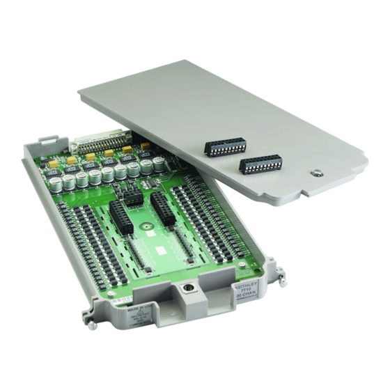
The 7710 20-channel Solid-state Differential Multiplexer with Automatic Cold Junction Compensation (CJC)
module offers 20 channels of 2-pole or 10 channels of 4-pole relay input that can be configured as two
independent banks of multiplexers. The relays are solid state, providing long life and low maintenance. It is ideal
for long-term data logging applications and for demanding high-speed applications.
Item shipped may vary from model pictured here.
The 7710 includes the following features:
Fast-actuating, long-life solid-state relays
DC and AC voltage measurement
Two-wire or four-wire resistance measurements (automatically pairs relays for four-wire measurements)
Temperature applications (RTD, thermistor, thermocouple)
Built-in cold junction reference for thermocouple temperature
Screw terminal connections
PA-847 Rev. C June 2023
Figure 1: 7710 20-Channel Differential Multiplexer Module
*PPA-847C*
Model 7710 Multiplexer Module
Instructions for use with the 2750
1
Advertisement
Table of Contents

Related Manuals for Tektronix KEITHLEY 7710


Summary of Contents for Tektronix KEITHLEY 7710
- Page 1 Model 7710 Multiplexer Module Keithley Instruments Instructions for use with the 2750 28775 Aurora Road Cleveland, Ohio 44139 1-800-833-9200 tek.com/keithley Introduction The 7710 20-channel Solid-state Differential Multiplexer with Automatic Cold Junction Compensation (CJC) module offers 20 channels of 2-pole or 10 channels of 4-pole relay input that can be configured as two independent banks of multiplexers.
-
Page 2: Wiring Procedure
Model 7710 Multiplexer Module Instructions for use with the 2750 The Model 7710 will operate properly when installed in one of the following instruments: Model 2700 equipped with B05 (or later) firmware Model 2701 equipped with A01 (or later) firmware ... - Page 3 Model 7710 Multiplexer Module Instructions for use with the 2750 Equipment needed: Flat-blade screwdriver Needle-nose pliers Cable ties To wire the 7710 module: 1. Make sure all power is discharged from the 7710 module. 2. Using a screwdriver, turn the access screw to unlock and open the cover, as shown in the following figure. Figure 2: Screw terminal access 3.
- Page 4 Model 7710 Multiplexer Module Instructions for use with the 2750 Figure 3: Proper procedure to remove terminal blocks 4. Using a small flat-blade screwdriver, loosen the terminal screws and install the wires as needed. The following figure shows the connections, including the connections to source and sense. Figure 4: Screw terminal channel designations PA-847 Rev.
-
Page 5: Module Configuration
Model 7710 Multiplexer Module Instructions for use with the 2750 5. Plug the terminal block into the module. 6. Route wire along the wire path and secure with cable ties as shown. The following figure shows connections to channels 1 and 2. Figure 5: Wire dressing 7. - Page 6 Model 7710 Multiplexer Module Instructions for use with the 2750 When using system channel operation for 4-wire measurements (including 4-wire ohms, RTD temperature, Ratio, and Channel Average), the channels are paired as follows: CH1 and CH11 CH6 and CH16 CH2 and CH12 CH7 and CH17 CH3 and CH13 CH8 and CH18...
-
Page 7: Typical Connections
Model 7710 Multiplexer Module Instructions for use with the 2750 For this command sequence, the digital multimeter (DMM) of the 2750 is electrically isolated from the test circuit. Refer to the Model 2750 Reference Manual for detail on multiple channel operation. Typical connections The following examples show typical wiring connections for the following types of measurements: ... -
Page 8: Connection Log
Model 7710 Multiplexer Module Instructions for use with the 2750 Figure 9: Four-wire resistance and RTD connections Figure 10: DC or AC voltage connections Connection log You can use the following table to record your connection information. PA-847 Rev. C June 2023... - Page 9 Model 7710 Multiplexer Module Instructions for use with the 2750 Connection log for the 7710 Channel Color Description Card Source Card Sense CH10 CH11 CH12 CH13 CH14 CH15 CH16 CH17 CH18 CH19 CH20 PA-847 Rev. C June 2023...
-
Page 10: Installation
Model 7710 Multiplexer Module Instructions for use with the 2750 Installation Before operating an instrument with a switching module, verify that the switching module is properly installed and the mounting screws are tightly fastened. If the mounting screws are not properly connected, an electrical shock hazard may be present. -
Page 11: Operation
Model 7710 Multiplexer Module Instructions for use with the 2750 Operation To prevent overheating or damage to the 7710 switching module relays, never exceed the following maximum signal levels between any two inputs or chassis: Any channel to any channel (1 to 20): 60 V dc or 42 V , 100 mA switched, 6 W, 4.2 VA maximum. - Page 12 Model 7710 Multiplexer Module Instructions for use with the 2750 Two-wire method Resistance measurements in the normal range (>100 Ω) are generally made using the 2-wire method (Ω2 function). The test current is forced through the test leads and the resistance being measured (R ).
-
Page 13: Voltage Measurements
Model 7710 Multiplexer Module Instructions for use with the 2750 Figure 11: Low-ohms measurements using the 4-wire method Assumptions: Virtually no current flows in the high-impedance sense circuit because of the high impedance of the voltmeter (V ). Therefore, the voltage drops across Channel 11 and test lead 1 and 4 are negligible and can be ignored. -
Page 14: Insertion Loss
Model 7710 Multiplexer Module Instructions for use with the 2750 Insertion loss Insertion loss is AC signal power lost between the input and the output. In general, as frequency increases, insertion loss increases. For the 7710 module, insertion loss is specified for a 50 Ω AC signal source routed through the module to a 50 Ω load. - Page 15 Model 7710 Multiplexer Module Instructions for use with the 2750 Heat sink temperature measurements Measuring the temperature of a heat sink is a typical test for a system that has temperature measurement capability. However, the 7710 module cannot be used if the heat sink is being floated at a dangerous voltage level (>60 V).
-
Page 16: Module Handling Precautions
Model 7710 Multiplexer Module Instructions for use with the 2750 Module handling precautions The solid state relays used on the 7710 module are static sensitive devices. Therefore, they can be damaged by electrostatic discharge (ESD). To prevent damage from ESD, only handle the module by the card edges. Do not touch the backplane connector terminals. -
Page 17: Calibration Setup
Model 7710 Multiplexer Module Instructions for use with the 2750 Calibration The following procedures calibrate the temperature sensors on the 7710 plug-in modules. Do not attempt to perform this procedure unless you are qualified, as described by the types of product users in the Safety precautions. -
Page 18: Factory Service
Model 7710 Multiplexer Module Instructions for use with the 2750 Calibration using the front panel To calibrate the 7710 using the front panel: 1. Connect the Model 7710 to the Model 7797 Calibration/Extender Board. Refer to Extender board connections (on page 17) for instruction. 2. -
Page 19: Safety Precautions
Safety precautions The following safety precautions should be observed before using this product and any associated instrumentation. Although some instruments and accessories would normally be used with nonhazardous voltages, there are situations where hazardous conditions may be present. This product is intended for use by personnel who recognize shock hazards and are familiar with the safety precautions required to avoid possible injury. - Page 20 The CAUTION heading in the user documentation explains hazards that could damage the instrument. Such damage may invalidate the warranty. The CAUTION heading with the symbol in the user documentation explains hazards that could result in moderate or minor injury or damage the instrument. Always read the associated information very carefully before performing the indicated procedure. Damage to the instrument may invalidate the warranty.
Need help?
Do you have a question about the KEITHLEY 7710 and is the answer not in the manual?
Questions and answers