
Related Manuals for Tektronix VX4286


Summary of Contents for Tektronix VX4286
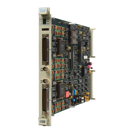
- Page 1 User Manual VX4286 32-Channel Analog/Digital Input Module 070-9143-02 This document applies for firmware version 1.00 and above.
- Page 2 Copyright Tektronix, Inc. All rights reserved. Tektronix products are covered by U.S. and foreign patents, issued and pending. Information in this publication supercedes that in all previously published material. Specifications and price change privileges reserved. Printed in the U.S.A. Tektronix, Inc., P.O. Box 1000, Wilsonville, OR 97070–1000...
- Page 3 Tektronix, with shipping charges prepaid. Tektronix shall pay for the return of the product to Customer if the shipment is to a location within the country in which the Tektronix service center is located. Customer shall be responsible for paying all shipping charges, duties, taxes, and any other charges for products returned to any other locations.
- Page 4 8444 AB Heerenveen The Netherlands declare under sole responsibility that the VX4286 and all options meets the intent of Directive 89/336/EEC for Electromagnetic Compatibility. Compliance was demonstrated to the following specifications as listed in the Official Journal of the European Communities:...
-
Page 8: General Safety Summary
Symbols and Terms Terms in this Manual. These terms may appear in this manual: WARNING. Warning statements identify conditions or practices that could result in injury or loss of life. VX4286 32-Channel Analog/Digital Input Module... - Page 9 CAUTION indicates a hazard to property including the product. Symbols on the Product. The following symbols may appear on the product: DANGER Protective Ground ATTENTION Double High Voltage (Earth) Terminal Refer to Manual Insulated VX4286 32-Channel Analog/Digital Input Module...
-
Page 10: Service Safety Summary
Use Care When Servicing With Power On. Dangerous voltages or currents may exist in this product. Disconnect power, remove battery (if applicable), and disconnect test leads before removing protective panels, soldering, or replacing components. To avoid electric shock, do not touch exposed connections. VX4286 32-Channel Analog/Digital Input Module... - Page 22 VXIbus Radiated Emissions: VXIbus Conducted Emissions:...
-
Page 152: Appendix A: Performance Verification
Appendix A: Performance Verification This Performance Verification procedure contains test sequences suitable for determining if the VX4286 functions, was adjusted properly, and meets the performance characteristics as warranted. The following skills are required to perform this procedure: Thorough knowledge of test instrument operation and proper measurement... -
Page 153: Equipment Required
Prerequisites The test sequences in this procedure are valid under the following conditions: The VX4286 module covers are in place and the module is installed in an approved VXIbus mainframe as described in Section 2 of the User Manual The VX4286 has passed the power-on self test... - Page 154 Item Number and Description Minimum Requirements Example Purpose 8. Adapter, BNC femal to 50 , BNC female to dual Clip Leads Tektronix part number Interconnecting electrical Clip Leads 013-0076-00 signals 9. Adapter, BNC male to Probe 50 , BNC male to oscilloscope probe...
- Page 155 TTL Output 25 Input 27 TTL Output 26 Input 28 TTL Output 27 Input 29 TTL Output 28 Input 30 TTL Output 29 Input 31 TTL Output 30 Daughter Bd. TTL Output 31 Common (input) Figure A–1: DD-50S Interconnect Assembly A–24 VX4286...
-
Page 156: Test Record
Appendix F: Performance Verification VX4286 Under-Test Configuration The VX4286 under-test must be installed in an approved VXIbus system. At a minimum, the system must contain the elements listed in Table A–2. Table A–2: Elements of a Minimum VX4286 Under-Test System... - Page 157 Appendix F: Performance Verification Table A–4: VX4286 Test Record VX4286 Serial Number: Temperature and Relative Humidity: Date of Last Calibration: Verification Performed by: Certificate Number: Date of Verification: VXIbus Interface Logical Address, IEEE Address, Slot No., MFG., Model, etc. System Configuration Response...
- Page 158 Appendix F: Performance Verification Table A–4: VX4286 Test Record (Cont.) DC Voltage Accuracy 50 Volt (Limits) 49.945 to 49.895 to 49.970 to –50.055 –50.105 –50.030 50.055 50.030 50.105 –49.945 –49.970 –49.895 Input 13 Input 14 Input 15 Input 16 Input 17...
- Page 159 Appendix F: Performance Verification Table A–4: VX4286 Test Record (Cont.) DC Voltage Accuracy 10 Volt (Limits) 9.985 to 9.980 to 9.990 to –10.015 –10.020 –10.010 10.015 10.010 10.020 –9.985 –9.990 –9.980 Input 8 Input 9 Input 10 Input 11 Input 12...
-
Page 160: Performance Verification Tests
Failed light will be on, the Power light will be off, and SYSFAIL* will be asserted. Following a successful VXIbus system startup sequence, the green PWR light on the VX4286 front panel indicates that the self test has passed and that all power supplies are operational. - Page 161 2. Send the self-test command to ensure module communication and general functionality. Following the command, verify that the front panel ERROR light is off and that there are no error responses queued up. VX4286 (Observe a “00,NO ADDITIONAL ERRORS TO REPORT..) A–30...
- Page 162 Interrupt, EQU OUT Out, ing the inputs), the generation of a VXIbus Request True interrupt, the EQU OUT pulse, the ability of the VX4286 to recognize an input data pulse of at least Minimum Data Pulse 3 µs duration and 150 mV in amplitude, and the generation of a corresponding Width, TTL Output TTL Output data pulse.
- Page 163 2.4µs). The EQU OUT pulse occurs about 200 µs after the function generator input pulse. 10. Perform a serial poll with the VX4286 and verify that a VXIbus Request True event is pending (an S displayed in the second display digit of the VX4521).
- Page 164 20 µs/division. Reset the trigger source to channel 2 and the trigger level to the 2nd graticule from the bottom of the display. 15. Reset the VX4286 to the power-on default state, to trigger on a 100 mV input level, with a capture equation specified to acquire “threshold crossing signals”...
- Page 165 All prerequisites listed on page A–22 1. Attach the DD-50S Interconnect Assembly to P4 as shown in Figure A–1. 2. Connect the Voltage Calibrator to input channels 0-to-7 of the VX4286 using a Dual-Banana connector a Coaxial cable, and a BNC to Clip Lead adapter.
- Page 166 11. Reacquire and verify the response to the limits shown in the Test Record. (8-15, 16-23, 24-31 on later passes) (Verify responses relative to the Test Record.) 12. Connect the Voltage Calibrator to input channels 8-to-15 of the VX4286 (as shown in Figure A–1) then repeat steps 3 to 11, substituting channel designation in place of 13.
- Page 167 Attach the BNC to Probe Tip Adapter to the other side of the BNC-T and insert the oscilloscope probe. 3. Reset the VX4286 to the power-on state, to enable the TTL Outputs, to assert the 500 kHz Time Tag signal on the EQU OUT connector and on TTL Outputs 15 and 31.
- Page 171 The VX4286 Module module must be calibrated every twelve months for the module to meet its published accuracy specifications. Calibrate the VX4786 Module at the temperature at which it will be operating. Calibration to the published accuracy specifications has been performed at Tektronix Inc. prior to shipping. Allow a ten...
Need help?
Do you have a question about the VX4286 and is the answer not in the manual?
Questions and answers