Cisco Firepower 1100 Series Hardware Installation Manual
Hide thumbs
Also See for Firepower 1100 Series:
- Installation manual (44 pages) ,
- Hardware installation manual (42 pages) ,
- Hardware installation manual (42 pages)
Table of Contents

Related Manuals for Cisco Firepower 1100 Series


Summary of Contents for Cisco Firepower 1100 Series
- Page 1 Cisco Firepower 1100 Series Hardware Installation Guide First Published: 2019-06-13 Americas Headquarters Cisco Systems, Inc. 170 West Tasman Drive San Jose, CA 95134-1706 http://www.cisco.com Tel: 408 526-4000 800 553-NETS (6387) Fax: 408 527-0883...
- Page 2 Cisco has more than 200 offices worldwide. Addresses and phone numbers are listed on the Cisco website at www.cisco.com/go/offices. Cisco and the Cisco logo are trademarks or registered trademarks of Cisco and/or its affiliates in the U.S. and other countries. To view a list of Cisco trademarks, go to this URL: www.cisco.com...
-
Page 3: Table Of Contents
C H A P T E R 3 Mount the Chassis Unpack and Inspect the Chassis Rack-Mount the Chassis C H A P T E R 4 Connect to the Console Port Connect to the Console Port with Microsoft Windows Cisco Firepower 1100 Series Hardware Installation Guide... - Page 4 Contents Connect to the Console Port with Mac OS X Connect to the Console Port with Linux C H A P T E R 5 Maintenance and Upgrade Replace the SSD Cisco Firepower 1100 Series Hardware Installation Guide...
-
Page 5: Overview
Product ID Numbers, on page 9 Features The Cisco Firepower 1100 series security appliances are a standalone modular security services platform. They are capable of running multiple security services simultaneously and so are targeted at the data center as a multiservice platform. See... - Page 6 The SPFs are hot-swappable. Power switch On rear panel Note To shut down the Firepower 1100 series gracefully, see the "Power Off the Device" section for FDM and FMC in the Cisco Firepower 1100 Series Getting Started Guide. Cisco Firepower 1100 Series Hardware Installation Guide...
- Page 7 Console Ports The Firepower 1100 series has two external console ports, a standard RJ-45 port and a USB Mini B serial port. Only one console port can be active at a time. When a cable is plugged into the USB console port, the RJ-45 port becomes inactive.
-
Page 8: Package Contents
Package Contents The following figure shows the package contents for the Firepower 1100 series. Note that the contents are subject to change, and your exact contents might contain additional or fewer items. Figure 2: Firepower 1100 Series Package Contents... -
Page 9: Serial Number Location
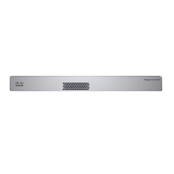
Figure 3: Compliance Label on the Firepower Chassis Front Panel The following figure shows the front panel of the Firepower 1100 series. Note that there are no connectors or LEDs on the front panel. Cisco Firepower 1100 Series Hardware Installation Guide... -
Page 10: Rear Panel
Rear Panel Figure 4: Firepower 1100 Series Front Panel Rear Panel The following figure shows the rear panel of the Firepower 1100 series. See Rear Panel LEDs, on page 7 for a description of the LEDs. Figure 5: Firepower 1100 Series Rear Panel... -
Page 11: Rear Panel Leds
Rear Panel LEDs The following figure shows the LEDs on the rear panel of the Firepower 1100 series and describes their states. Figure 6: Firepower 1100 Series Rear Panel LEDs Network Network Status of the network ports. -
Page 12: Hardware Specifications
Note Replace the SSD , on page for the procedure for replacing a failed SSD. Hardware Specifications The following table contains hardware specifications for the Firepower 1100 series. Table 2: Firepower 1100 Series Hardware Specifications Specification 1120 1140 Dimensions (H x W x D) 17.2 in. -
Page 13: Product Id Numbers
31.7 dBa at room temperature Product ID Numbers The following table lists the field-replaceable PIDs associated with the Firepower 1100 series. The spare components are ones that you can order and replace yourself. If any internal components fail, you must RMA the entire chassis. - Page 14 Overview Product ID Numbers Cisco Firepower 1100 Series Hardware Installation Guide...
-
Page 15: Installation Preparation
(EMI) that might disrupt other equipment; and they direct the flow of cooling air through the chassis. Do not operate the system unless all cards, faceplates, front covers, and rear covers are in place. Cisco Firepower 1100 Series Hardware Installation Guide... - Page 16 20 A, 120 V, and 16 A, 250 V Warning Statement 1045—Short-Circuit Protection This product requires short-circuit (overcurrent) protection to be provided as part of the building installation. Install only in accordance with national and local wiring regulations. Cisco Firepower 1100 Series Hardware Installation Guide...
-
Page 17: Safety Recommendations
• Wear safety glasses if you are working under any conditions that might be hazardous to your eyes. • Do not perform any action that creates a potential hazard to people or makes the equipment unsafe. • Never attempt to lift an object that is too heavy for one person. Cisco Firepower 1100 Series Hardware Installation Guide... -
Page 18: Maintain Safety With Electricity
If no wrist strap is available, ground yourself by touching the metal part of the chassis. For safety, periodically check the resistance value of the antistatic strap, which should be between one and 10 megohms. Cisco Firepower 1100 Series Hardware Installation Guide... -
Page 19: Site Environment
• If you are using dual redundant (1+1) power supplies, we recommend that you use independent electrical circuits for each power supply. • Install an uninterruptible power source for your site, if possible. Cisco Firepower 1100 Series Hardware Installation Guide... -
Page 20: Rack Configuration Considerations
• Baffles can help to isolate exhaust air from intake air, which also helps to draw cooling air through the chassis. The best placement of the baffles depends on the airflow patterns in the rack. Experiment with different arrangements to position the baffles effectively. Cisco Firepower 1100 Series Hardware Installation Guide... -
Page 21: Mount The Chassis
• Description of damage • Effect of damage on the installation Rack-Mount the Chassis The chassis ships with rack-mount brackets, which you can install on the front or the rear of the chassis. Cisco Firepower 1100 Series Hardware Installation Guide... - Page 22 Figure 7: Chassis Installed in the Rack Left rack-mount bracket Right rack-mount bracket Cold aisle (chassis rear panel) Hot aisle (chassi front panel) Air flow direction Cisco Firepower 1100 Series Hardware Installation Guide...
- Page 23 Mount the Chassis Rack-Mount the Chassis What to do next You can now install the cables and power cord, as described in the Cisco Firepower 1100 Series Getting Started Guide. Cisco Firepower 1100 Series Hardware Installation Guide...
- Page 24 Mount the Chassis Rack-Mount the Chassis Cisco Firepower 1100 Series Hardware Installation Guide...
-
Page 25: Connect To The Console Port
Obtain the appropriate driver (Cisco_usbconsole_driver_X_X_zip, where X is a revision number) for your model from the Cisco Download Software site, USB Console Software category. Step 2 Install the driver. Step 3 Connect a 5-pin USB Mini B to the console port as shown in the following figure. Cisco Firepower 1100 Series Hardware Installation Guide... -
Page 26: Connect To The Console Port With Mac Os X
Use the Finder to go to Applications > Utilities > Terminal. Step 2 Connect the OS X USB port to the chassis. Step 3 Enter the following commands to find the OS X USB port number: Cisco Firepower 1100 Series Hardware Installation Guide... -
Page 27: Connect To The Console Port With Linux
Connect to the USB port with the following command followed by the chassis USB port speed Example: root@usb-suse /dev# screen /dev/ttyACM0 9600 Step 5 To disconnect the Linux USB console from the Terminal window, enter Ctrl-a followed by : then quit. Cisco Firepower 1100 Series Hardware Installation Guide... - Page 28 Connect to the Console Port Connect to the Console Port with Linux Cisco Firepower 1100 Series Hardware Installation Guide...
-
Page 29: Maintenance And Upgrade
• Replace the SSD , on page 25 Replace the SSD The Firepower 1100 series ships with an SSD installed. You can replace this SSD should it fail. You must power off the chassis to do replace the SSD. Caution You will lose your configuration after you replace the existing SSD with a new SSD. - Page 30 Replace the SSD Step 4 Check the SSD LED to make sure the SSD is seated properly and functioning. See Rear Panel LEDs, on page 7 for a description of the SSD LED. Cisco Firepower 1100 Series Hardware Installation Guide...
Need help?
Do you have a question about the Firepower 1100 Series and is the answer not in the manual?
Questions and answers