
Subscribe to Our Youtube Channel
Related Manuals for Abit IS-10


Summary of Contents for Abit IS-10
- Page 1 IS-10 / IS-11 / IS-12 Socket 478 System Board User’s Manual 4200-0383-02 Rev. 1.00...
- Page 2 This document contains materials protected under International Copyright Laws. All rights reserved. No part of this manual may be reproduced, transmitted or transcribed without the expressed written permission of the manufacturer and authors of this manual. IS-10 / IS-11 / IS-12...
-
Page 3: Table Of Contents
Table Of Contents 快速安裝指引 ..................2 速いインストールガイド ..............4 Schneller Installation Führer............. 6 Guide Rapide d'Installation............... 8 Быстро Направляющий выступ Установки......10 Guida Rapida Dell'Installazione ............. 12 Chapter 1. Introduction ............ 1-1 1.1. Features & Specifications............1-1 1.2. Layout Diagram..............1-3 1.3. - Page 4 3.11. Set User Password ..............3-22 3.12. Save & Exit Setup ..............3-22 3.13. Exit Without Saving ............. 3-22 Chapter 4. Driver Installation .......... 4-1 4.1. Setup Items ................4-2 Appendix A. How to Get Technical Support ..... A-1 IS-10 / IS-11 / IS-12...
- Page 5 User’s Manual User’s Manual...
-
Page 6: 快速安裝指引
快速安裝指引 快速安裝指引 安裝處理器的散熱片以及風扇組件 (Zero Insertion Force, ZIF) ® ® Socket 478 Intel Pentium 4 CPU ® Pentium 4 Socket 478 Socket 478 ® 注意: Pentium 注意: IS-10 / IS-11 / IS-12... - Page 7 快速安裝指引 將主機板安裝到機殼上 安裝記憶體模組 DIMM DIMM DIMM DIMM DIMM DIMM DIMM DIMM DIMM DIMM 注意: 連接器、連接頭以及附加卡的安裝 SCSI 將電源供應器的電源線連接頭與主機板上的 ATX12V 電源接頭連接起來 ATX12V BIOS 的設定 BIOS User’s Manual...
-
Page 8: 速いインストールガイド
速いインストールガイド 速いインストールガイド ZIF ( ® ® ) Socket 478 Intel Pentium ® Pentium Socket 478 ® 注意:Pentium IS-10 / IS-11 / IS-12... - Page 9 速いインストールガイド 注意: DIMM 2. DIMM DIMM DIMM 5. DIMM 注意 : SCSI ATX12V 出 ATX12V 奥 着 BIOS ハ ウ 了 BIOS Setup 移 User’s Manual...
-
Page 10: Schneller Installation Führer
Lüfter und Haltemechanismuseinheit nieder, bis er in die Basis des Haltemoduls einschnappt. 6. Lüfter und Haltemechanismus-Einheit und die Basis des Haltemoduls sollten nun fest miteinander verriegelt sein und das Kühlblech sich in ihrem Innern befinden.. IS-10 / IS-11 / IS-12... - Page 11 Schneller Installation Führer Achtung: Vergessen Sie nicht, die korrekte Busfrequenz und -Multiplikator für Ihren Prozessor einzustellen. Installieren der Hauptplatine im Gehäuse Nach der Installation des Prozessors können Sie anfangen die Hauptplatine im Computergehäuse zu befestigen. Die meisten Gehäuse haben eine Bodenplatte, auf der sich eine Reihe von Befestigungslöcher befinden, mit deren Hilfe Sie die Hauptplatine sicher verankern können und zugleich Kurzschlüsse verhindern.
-
Page 12: Guide Rapide D'installation
Base du Module de Retient. 6. Le Ventilateur, le Mécanisme de Retient et la Base du Module de Retient doivent maintenant être verrouillés l’un sur l’autre avec le dissipateur de chaleur à l’intérieur. IS-10 / IS-11 / IS-12... - Page 13 Guide Rapide d'Installation Attention: N’oubliez pas de programmer la fréquence de bus correcte et le multiple pour votre processeur. Installer la Carte Mre dans le Châssis Une fois que vous aurez installé le processeur sur la carte mère, vous pourrez commencer à fixer la carte mère sur le châssis.
-
Page 14: Быстро Направляющий Выступ Установки
механизма вошли в предназначенные отверстия и защелкнулись. 5. Зафиксируйте вентилятор на основании радиатора, опустив рычажки, расположенные с обеих сторон фиксирующего механизма. 6. Вентилятор, фиксирующий механизм и основание радиатора должны быть надежно закреплены вместе с вентилятором. IS-10 / IS-11 / IS-12... - Page 15 Быстро Направляющий выступ Установки Внимание: Установите соответствующие частоту и кратность шины процессора. Установка материнской платы в корпус После установки процессора на материнскую плату можно начинать установку материнской платы в корпус. Большая часть корпусов оборудована основанием, в котором проделаны монтажные отверстия, которые позволяют надежно закрепить материнскую плату и предотвратить короткие...
-
Page 16: Guida Rapida Dell'installazione
6. La ventolina, il gruppo del meccanismo di trattenimento e la base del modulo di trattenimento ora dovrebbero essere fissati gli uni agli altri trattenendo al loro interno il dispersore di calore. IS-10 / IS-11 / IS-12... - Page 17 Guida Rapida Dell'Installazione Attenzione: Non dimenticare di impostare la corretta frequenza multipla e BUS per il processore. Installazione della scheda madre sul telaio Dopo avere installato il processore sulla scheda madre si può iniziare a fissare la scheda madre sul telaio. Innanzi tutto è...
- Page 18 IS-10 / IS-11 / IS-12...
-
Page 19: Chapter 1. Introduction
• Supports Plug-and-Play (PNP) • Supports Advanced Configuration Power Interface (ACPI) • Supports Desktop Management Interface (DMI) • Write-Protect Anti-Virus function by AWARD BIOS • On board 10/100Mb LAN (For IS-10/IS-12) • On board Gigabit LAN (For IS-11) User’s Manual... - Page 20 2x USB 2.0 Connectors, 1x RJ-45 LAN Connector Miscellaneous • Micro ATX Form Factor (9.6” x 9.2”) • Hardware Monitoring - including Fan Speed, Voltages, CPU and System Temperature Specifications and information contained herein are subject to change without notice. IS-10 / IS-11 / IS-12...
-
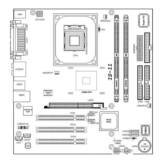
Page 21: Layout Diagram
Introduction 1.2. Layout Diagram User’s Manual... -
Page 22: Jumpers & Connectors Description
Front Panel Audio Connection Header FPIO1 Front Panel Switch Connection Headers FP-USB1/FP-USB2 Additional USB Port Connection Header IDE1/IDE2 Hard Disk Drive Connectors PCI1/PCI2/PCI3 32bit/33MHz PCI Slots SATA1/SATA2 Serial ATA Connectors SMB1 System Management Bus Header IS-10 / IS-11 / IS-12... -
Page 23: Chapter 2. Hardware Setup
Hardware Setup Chapter 2. Hardware Setup 2.1. Precautions Please pay attention to the following precautions before setting up any hardware. 1. Always switch off the power supply and unplug the power cord from the wall outlet before installing the board or changing any settings. 2. -
Page 24: Installing The System Board
5. Tightens all the screw holes. ATTENTION: To prevent shorting the PCB circuit, please REMOVE the metal studs or spacers if they are already secured on the chassis base and are without mounting-holes on the system board to align with. IS-10 / IS-11 / IS-12... -
Page 25: Cpu And Heatsink Supporting-Base
Hardware Setup ® 2.3. Install Pentium 4 CPU and Heatsink Supporting-Base ® This motherboard provides a ZIF (Zero Insertion Force) Socket 478 to install Intel ® Pentium 4 CPU. The CPU you bought should have a kit of heatsink and cooling fan ®... -
Page 26: System Memory
2GB. 2.4.1. Memory Configuration Table DIMM DIMM Module Total Memory 128MB, 256MB, 512MB, 1GB 128MB ~ 1GB 128MB, 256MB, 512MB, 1GB 128MB ~ 1GB 128MB ~ 2GB Total System Memory IS-10 / IS-11 / IS-12... -
Page 27: Installing And Removing Memory Modules
Hardware Setup 2.4.2. Installing and Removing Memory Modules Power off the computer and unplug the AC power cord before installing or removing memory modules. 1. Locate the DIMM slot on the board. 2. Hold two edges of the DIMM module carefully, keep away of touching its connectors. -
Page 28: Connectors, Headers, And Switches
2.5.1. ATX Power Connectors It would be recommended to supply an ATX12V power with 300W, 20A +5VDC capacity at least for heavily loaded system, and 720mA +5VSB at least for supporting Wake-On-LAN feature. IS-10 / IS-11 / IS-12... -
Page 29: Fan Connectors
Hardware Setup 2.5.2. FAN Connectors These 3-pin connectors each provide power to the cooling fans installed in your system. The CPU must be kept cool by using a powerful fan with heatsink. The system is capable of monitoring the speed of the CPU fan. •... -
Page 30: Cmos Memory Clearing Header
Pin 2-3 shorted: Clear CMOS memory. ATTENTION: Turn the system power off first (including the +5V standby power) before clearing the CMOS memory. Failing to do so may cause your system to work abnormally or malfunction. IS-10 / IS-11 / IS-12... -
Page 31: Accelerated Graphics Port Slot
Hardware Setup 2.5.4. Accelerated Graphics Port Slot This slot supports an optional AGP graphics card up to AGP 4X mode only. Please refer to our Web site for more information on graphics cards. ATTENTION: This motherboard does not support 3.3V AGP cards. Use only 1.5V or 0.8V AGP cards. -
Page 32: Front Panel Switches & Indicators Connection Headers
Connects to the Suspend LED cable (if there is one) of chassis front panel. • PWR-ON (Pin 6, 8): Connects to the Power Switch cable of chassis front panel. • PLED (Pin 16, 18, 20): Connects to the Power LED cable of chassis front panel. IS-10 / IS-11 / IS-12... -
Page 33: Front Panel Audio Connection Header
Hardware Setup 2-11 2.5.6. Front Panel Audio Connection Header This header provides the connection to audio connector at front panel. • To use the audio connector at front panel, remove all the jumpers on this header, and then connect to front panel by the extension cable provided with the chassis. -
Page 34: Additional Usb Port Connection Header
Additional USB Port Connection Header These headers each provides 2 additional USB 2.0 ports connection through an USB cable designed for USB 2.0 specifications. Pin Assignment Pin Assignment Data0 - Data1 - Data0 + Data1 + Ground Ground IS-10 / IS-11 / IS-12... -
Page 35: System Management Bus Header
Hardware Setup 2-13 2.5.8. System Management Bus Header This header is reserved for system management bus (SM bus). The SM bus is a specific implementation of an I C bus. I C is a multi-master bus, which means that multiple chips can be connected to the same bus and each one can act as a master by initiating a data transfer. -
Page 36: Additional Ieee1394 Port Headers
Chapter 2 2.5.9. Additional IEEE1394 Port Headers These headers each provide one additional IEEE1394 port connection through an extension cable and bracket. Pin Assignment Pin Assignment TPA0 + TPA0 - TPB0 + TPB0 - +12V +12V IS-10 / IS-11 / IS-12... -
Page 37: Internal Audio Source Connectors
Hardware Setup 2-15 2.5.10. Internal Audio Source Connectors These connectors connect to the audio output of internal CD-ROM drive or add-on card. User’s Manual... -
Page 38: Floppy Disk Drive Connector
2. Install the other end(s) of ribbon cable into the disk drive connector(s). The colored edge of the ribbon cable should be also aligned with pin-1 of disk drive connector. The endmost connector should be attached to the drive designated as Drive A. IS-10 / IS-11 / IS-12... -
Page 39: Ide Disk Drive Connectors
Hardware Setup 2-17 2.5.12. IDE Disk Drive Connectors These IDE ports each connects up to two IDE drives at Ultra ATA/100 mode by one 40-pin, 80-conductor, and 3-connector Ultra ATA/66 ribbon cables. Connect the single end (blue connector) at the longer length of ribbon cable to the IDE port on system board, and the other two ends (gray and black connector) at the shorter length of the... -
Page 40: Serial Ata Connectors
2-18 Chapter 2 2.5.13. Serial ATA Connectors These connectors are provided to attach one Serial ATA device at each channel via Serial ATA cable. IS-10 / IS-11 / IS-12... -
Page 41: Cpu Core Voltage Selector
Hardware Setup 2-19 2.5.14. CPU Core Voltage Selector This header uses a jumper to adjust the CPU core voltage. • Pin 1-2 shorted (default): Normal operation. • Pin 2-3 shorted: Raise the CPU core voltage by 0.1V. User’s Manual... -
Page 42: External I/O Panel
5.1-channel or regular 2-channel audio system. • LAN: Connects to Local Area Network. • USB1/USB2: Connects to USB devices such as scanner, digital speakers, monitor, mouse, keyboard, hub, digital camera, joystick etc. IS-10 / IS-11 / IS-12... -
Page 43: Chapter 3. Bios Setup
BIOS Setup Chapter 3. BIOS Setup This motherboard provides a programmable EEPROM that you can update the BIOS utility. The BIOS (Basic Input/Output System) is a program that deals with the basic level of communication between processor and peripherals. Use the BIOS Setup program only when installing motherboard, reconfiguring system, or prompted to “Run Setup”. -
Page 44: Standard Cmos Features
This item sets the date you specify (usually the current date) in the format of [Month], [Date], and [Year]. Time (hh:mm:ss) This item sets the time you specify (usually the current time) in the format of [Hour], [Minute], and [Second]. IS-10 / IS-11 / IS-12... - Page 45 BIOS Setup IDE Channel 1 Master/Slave, IDE Channel 2 Master/Slave Click <Enter> key to enter its submenu: IDE HDD Auto-Detection This item allows you to detect the parameters of IDE drives by pressing the <Enter> key. The parameters will automatically be shown on the screen. IDE Primary Master When set to [Auto], the BIOS will automatically check what kind of IDE drive you are using.
- Page 46 [CGA 40]: (Color Graphics Adapter) Power up in 40-column mode. [CGA 80]: (Color Graphics Adapter) Power up in 80-column mode. [Mono]: (Monochrome adapter) Includes high-resolution monochrome adapters. Halt On This item determines whether the system stops if an error is detected during system boot-up. IS-10 / IS-11 / IS-12...
- Page 47 BIOS Setup [All Errors]: The system-boot will stop whenever the BIOS detect a non-fatal error. [No Errors]: The system-boot will not stop for any error detected. [All, But Keyboard]: The system-boot will stop for all errors but keyboard error. [All, But Diskette]: The system-boot will stop for all errors but disk error. [All, But Disk/Key]: The system boot will stop for all errors but disk or keyboard error.
-
Page 48: Advanced Bios Features
This item controls CPU L1 & L2 caches. Set to [Disabled] to slow down the memory access speed only for some old and poorly written programs. Leave this item to its default [Enabled] setting. Hyper-Threading Technology This option enables or disables the processor’s Hyper-Threading Technology IS-10 / IS-11 / IS-12... - Page 49 BIOS Setup Leave this item to its default setting to enable the simultaneous multi-threaded (SMT) processor so as to make one physical processor looks like two logical processors to the OS and applications. This option is for CPU with Hyper-Threading Technology only. For more information on “Hyper-Threading Technology”, please visit Intel Web site at http://www.intel.com/homepage/land/hyperthreading.htm http://www.intel.com/design/chipsets/ht/.
-
Page 50: Advanced Chipset Features
This item controls the latency between the DRAM read command and the time that the data becomes actually available. Act. to Precharge Delay This item controls the number of DRAM clocks used for the DRAM parameters. IS-10 / IS-11 / IS-12... - Page 51 BIOS Setup DRAM RAS# to CAS# Delay This item controls the latency between the DRAM active command and the read/write command. DRAM RAS# Precharge This item controls the idle clocks after issuing a precharge command to the DRAM. AGP Aperture Size This option specifies the amount of system memory that can be used by the AGP device.
-
Page 52: Integrated Peripherals
3-10 Chapter 3 3.4. Integrated Peripherals Onboard IDE Device: Click <Enter> key to enter its submenu: IS-10 / IS-11 / IS-12... - Page 53 BIOS Setup 3-11 IDE Bus Master This option enables or disables the IDE bus mastering capability under the DOS environment. Onboard IDE-1 Controller This item enables or disables the onboard IDE-1 controller. Onboard IDE-2 Controller This item enables or disables the onboard IDE-2 controller. Onboard S-ATA Controller This item determines the function for on-chip Serial ATA.
- Page 54 Logical IDE-1 Logical IDE-2 • OnChip IDE-1 and IDE-2 controller SATA disabled • SATA1 serves as IDE-2 Master Only • SATA2 serves as IDE-1 Master Logical IDE-2 Logical IDE-1 • OnChip IDE-1 and IDE-2 controller disabled IS-10 / IS-11 / IS-12...
- Page 55 BIOS Setup 3-13 Onboard PCI Device: Click <Enter> key to enter its submenu: USB Controller This option enables or disables the USB controller. USB 2.0 Controller This option enables or disables the USB 2.0 controller. USB Keyboard Support This item allows you to select [BIOS] for using USB keyboard in DOS environment, or [OS] in OS environment.
- Page 56 [Mouse Right]: Double click the mouse right button to power on the system. [Any KEY]: Use any keyboard keys to power on the system. [BUTTON ONLY]: Use only the power button to power on the system. IS-10 / IS-11 / IS-12...
- Page 57 BIOS Setup 3-15 [Keyboard 98]: Use the power-on button on the “Keyboard 98” compatible keyboard to power on the system. NOTE: The mouse wake up function can only be used with the PS/2 mouse, not with the COM port or USB type. Some PS/2 mice cannot wake up the system because of compatible problems.
- Page 58 EPP Mode Select This item selects the EPP mode. ECP Mode Use DMA This item selects the DMA channel of the parallel port. PWRON After PWR-Fail This item sets the system action after a power failure. IS-10 / IS-11 / IS-12...
-
Page 59: Power Management Setup
BIOS Setup 3-17 3.5. Power Management Setup ACPI Suspend Type This item selects the type of Suspend mode. [S1(POS)]: Enables the Power On Suspend function. [S3(STR)]: Enables the Suspend to RAM function. USB Dev Wake-Up From S3 When set to [Enabled], this item allows you to use a USB device to wake up a system that is in the S3 (STR - Suspend To RAM) state. - Page 60 [1-31]: This option selects a date you would like the system to power-on. The system will power-on on the date set, and the time set in the “Time (hh:mm:ss) Alarm” item. Resume Time (hh:mm:ss) This item sets the time you would like the system to power-on. IS-10 / IS-11 / IS-12...
-
Page 61: Pnp/Pci Configurations
BIOS Setup 3-19 3.6. PnP/PCI Configurations Force Update ESCD If you want to clear ESCD data next time you boot up, and ask the BIOS to reset the settings for the Plug & Play ISA Card and the PCI Card, select Enabled. But the next time you boot up, this option will automatically be set as Disabled. - Page 62 3-20 Chapter 3 IRQ Resources Click <Enter> key to enter its submenu: This item sets each system interrupt to either [PCI Device] or [Reserved]. IS-10 / IS-11 / IS-12...
-
Page 63: Pc Health Status
BIOS Setup 3-21 3.7. PC Health Status Shutdown Temperature This item sets the temperature that would shutdown the system automatically in order to prevent system overheats. CPU Warning Temperature This item selects the CPU’s warning temperature limit. Once the system has detected that the CPU’s temperature exceeded the limit, warning beeps will sound. -
Page 64: Load Fail-Safe Defaults
BIOS setup (but can’t change its contents). 3.12. Save & Exit Setup This option saves your selections and exits the setup menu. 3.13. Exit Without Saving This option exits the setup menu without saving any change. IS-10 / IS-11 / IS-12... -
Page 65: Chapter 4. Driver Installation
Driver Installation Chapter 4. Driver Installation All the necessary drivers are included within the Drivers & Utilities CD that came packaged with your board. The display shown in the following figure should appear after inserting this CD into your CD-ROM drive, if not, enter [My Computer] [CD-ROM] Drive double click [autorun.exe]. -
Page 66: Setup Items
View the user’s manual in PDF file. • Utility Click to enter the sub-screen for installing DirectX, Acrobat Reader, and Award Flash utility software. • Browse CD Browse the contents of this CD-ROM. • Close Exit the CD setup Items Menu. IS-10 / IS-11 / IS-12... -
Page 67: Appendix A. How To Get Technical Support
3. Check the ABIT Technical Terms Guide and FAQ on our Website. We are trying to expand and make the FAQs more helpful and information rich. Let us know if you have any suggestions. - Page 68 How they serve you is also a good reference for your next purchase. 6. Contacting ABIT. If you feel that you need to contact ABIT directly you can send email to the ABIT technical support department. First, please contact the support team for the branch office closest to you.
- Page 69 Stevenage, Herts SG1 4QX, U.K. Tel: 44-1438-228888 Fax: 44-1438-226333 sales@abitcomputer.co.uk technical@abitcomputer.co.uk Germany, Benelux (Belgium, Netherlands, Luxembourg), Denmark, Norway, Sweden, Finland, and Switzerland: AMOR Computer B.V. (ABIT’s European Office) Van Coehoornstraat 7, 5916 PH Venlo, The Netherlands Tel: 31-77-3204428 Fax: 31-77-3204420 sales@abit.nl technical@abit.nl http://www.abit.nl...
- Page 70 8+ GMT time. In addition, we have holidays that may be different from those in your country. ABIT Computer Corporation No.323, Yang Guang St., Neihu, Taipei, 114, Taiwan Tel: 886-2-8751-8888 Fax: 886-2-8751-3382 server_sales@abit.com.tw market@abit.com.tw technical@abit.com.tw http://www.abit.com.tw IS-10 / IS-11 / IS-12...
- Page 71 Please contact the reseller from whom you bought the product. You should be able to get RMA service there. 8. Reporting Compatibility Problems to ABIT. Because of tremendous number of email messages we receive every day, we are forced to give greater weight to certain types of messages than to others.
-
Page 72: Technical Support Form
Company Name: Phone Number: Contact Person: Fax Number: E-mail Address: Model BIOS ID # Motherboard Model No. DRIVER REV OS/Application Hardware Name Brand Specifications IDE1 IDE2 IDE1 CD-ROM-Drive IDE2 System Memory ADD-ON CARD Problem Description: IS-10 / IS-11 / IS-12...
Need help?
Do you have a question about the IS-10 and is the answer not in the manual?
Questions and answers