
Related Manuals for Abit IS7-G


Summary of Contents for Abit IS7-G
- Page 1 IS7 Series (IS7-G, IS7, IS7-E, IS7-E2, IS7-M, IS7-V2) Intel Pentium 4 System Board Socket 478 User’s Manual 4200-0375-09 Rev. 1.05...
- Page 2 Copyright and Warranty Notice The information in this document is subject to change without notice and does not represent a commitment on part of the vendor, who assumes no liability or responsibility for any errors that may appear in this manual. No warranty or representation, either expressed or implied, is made with respect to the quality, accuracy or fitness for any particular part of this document.
-
Page 3: Table Of Contents
Быстро Направляющий выступ Установки ........10 Guida Rapida Dell'Installazione ............12 Chapter 1. Introduction ................1-1 1-1. Features & Specifications ................1-1 1-2. Layout Diagram (IS7-G/IS7/IS7-E)............1-4 1-3. Layout Diagram (IS7-E2) ................1-5 1-4. Layout Diagram (IS7-M) .................1-6 1-5. Layout Diagram (IS7-V2)................1-7 Chapter 2. - Page 4 Save & Exit Setup ..................3-25 3-13. Exit Without Saving................3-25 Appendix A. Install Intel Chipset Software Utility..........A-1 Appendix B. Install Intel Application Accelerator RAID (IS7-G, IS7) ....B-1 Appendix C. Install Audio Driver ................. C-1 Appendix D. Install LAN Driver ................D-1 Appendix E.
- Page 5 User’s Manual User’s Manual...
-
Page 6: 快速安裝指引
快速安裝指引 快速安裝指引 安裝處理器的散熱片以及風扇組件 (Zero Insertion Force, ZIF) ® ® Socket 478 Intel Pentium 4 CPU ® Pentium 4 Socket 478 Socket 478 ® 注意: Pentium 注意: IS7 Series... - Page 7 快速安裝指引 將主機板安裝到機殼上 安裝記憶體模組 DIMM DIMM DIMM DIMM DIMM DIMM DIMM DIMM DIMM DIMM 注意: 連接器、連接頭以及附加卡的安裝 SCSI 將電源供應器的電源線連接頭與主機板上的 ATX12V 電源接頭連接起來 ATX12V BIOS 的設定 BIOS User’s Manual...
-
Page 8: 速いインストールガイド
速いインストールガイド 速いインストールガイド ZIF ( ® ® ) Socket 478 Intel Pentium ® Pentium Socket 478 ® 注意:Pentium IS7 Series... - Page 9 速いインストールガイド 注意: DIMM 2. DIMM DIMM DIMM 5. DIMM 注意 : SCSI ATX12V 出 ATX12V 奥 着 BIOS ハ ウ 了 BIOS Setup 移 User’s Manual...
-
Page 10: Schneller Installation Führer
Schneller Installation Führer Schneller Installation Führer Beziehen Sie sich bitte für detaillierte Informationen über diese Hauptplatine auf die vollständige Version des Benutzerbuchs. Diese Schnellinstallationsanleitung ist für erfahrene Systemaufbauer gedacht. Ist es Ihr erster Versuch ein Computersystem aufzubauen, dann empfehlen wir Ihnen zuerst das vollständige Benutzerhandbuch zu lesen oder einen Techniker zum Aufbauen des Systems zu Hilfe zu holen. - Page 11 Schneller Installation Führer Achtung: Vergessen Sie nicht, die korrekte Busfrequenz und -Multiplikator für Ihren Prozessor einzustellen. Installieren der Hauptplatine im Gehäuse Nach der Installation des Prozessors können Sie anfangen die Hauptplatine im Computergehäuse zu befestigen. Die meisten Gehäuse haben eine Bodenplatte, auf der sich eine Reihe von Befestigungslöcher befinden, mit deren Hilfe Sie die Hauptplatine sicher verankern können und zugleich Kurzschlüsse verhindern.
-
Page 12: Guide Rapide D'installation
Guide Rapide d'Installation Guide Rapide d'Installation Pour des informations relatives à cette carte mère plus détaillées, veuillez vous référer à notre version complète du manuel utilisateur. Ce guide d’installation rapide est créé pour les assembleurs système expérimentés. S’il s’agit de votre premier essai pour installer un ordinateur, nous vous suggérons de lire d’abord le manuel en version complète ou de demander l’aide d’un technicien pour vous aider à... - Page 13 Guide Rapide d'Installation Attention: N’oubliez pas de programmer la fréquence de bus correcte et le multiple pour votre processeur. Installer la Carte Mre dans le Châssis Une fois que vous aurez installé le processeur sur la carte mère, vous pourrez commencer à fixer la carte mère sur le châssis.
-
Page 14: Быстро Направляющий Выступ Установки
Быстро Направляющий выступ Установки Быстро Направляющий выступ Установки Более подробные сведения о материнской плате приведены в руководстве пользователя. Краткое руководство по установке предназначено для опытных специалистов. Если вы собираете компьютер впервые, ознакомьтесь сперва с руководством пользователя или попросите техника помочь в настройке компьютерной системы. Установка... - Page 15 Быстро Направляющий выступ Установки Внимание: Установите соответствующие частоту и кратность шины процессора. Установка материнской платы в корпус После установки процессора на материнскую плату можно начинать установку материнской платы в корпус. Большая часть корпусов оборудована основанием, в котором проделаны монтажные отверстия, которые позволяют надежно закрепить материнскую плату и предотвратить короткие...
-
Page 16: Guida Rapida Dell'installazione
Guida Rapida Dell'Installazione Guida Rapida Dell'Installazione Per maggiori e dettagliate informazioni su questa scheda madre si prega di fare riferimento alla versione integrale del Manuale utente. Questa guida all’installazione veloce è intesa per costruttori esperi di sistemi. Se questa è la prima volta che si cerca di installare un sistema, si consiglia di leggere, innanzi tutto, la versione integrale del manuale oppure di chiedere aiuto ad un tecnico per l’installazione. - Page 17 Guida Rapida Dell'Installazione Attenzione: Non dimenticare di impostare la corretta frequenza multipla e BUS per il processore. Installazione della scheda madre sul telaio Dopo avere installato il processore sulla scheda madre si può iniziare a fissare la scheda madre sul telaio. Innanzi tutto è...
- Page 18 14 14 IS7 Series IS7 Series...
-
Page 19: Chapter 1. Introduction
Onboard 2 channels of Serial ATA 150MB/s data transfer rate via ICH5 South Bridge (IS7-E/IS7-M/IS7-E2/IS7-V2) 7. USB 2.0 • 8x USB 2.0 ports support 480 Mb/s data transfer rate 8. IEEE 1394 • Supports IEEE 1394a at 400/200/100 Mb/s data transfer rate (IS7-G/IS7) User’s Manual... - Page 20 Chapter 1 9. Audio • Onboard 6-Channel AC 97 CODEC • Professional digital audio interface supports S/PDIF In/Out (IS7-G/IS7/IS7-E) 10. ABIT Engineered ™ • ABIT SoftMenu Technology ™ • ABIT EQ ™ • ABIT FANEQ (IS7-G/IS7/IS7-E/IS7-M/IS7-E2) ™ • ABIT FlashMenu 11.
- Page 21 Introduction 14. Order Information Model Chipset SB SATA PCI SATA IEEE 1394 IS7-G 865PE + ICH5R 10/100/1000M RAID 0/1 RAID 0/1 3 Ports 865PE + ICH5R 10/100M RAID 0/1 3 Ports IS7-E 865PE + ICH5 10/100M 2 Ports IS7-E2 865PE + ICH5...
-
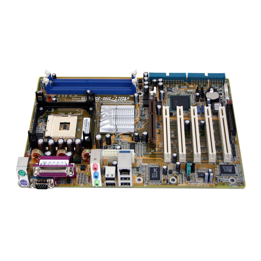
Page 22: Layout Diagram (Is7-G/Is7/Is7-E)
Chapter 1 1-2. Layout Diagram (IS7-G/IS7/IS7-E) IS7 Series... -
Page 23: Layout Diagram (Is7-E2)
Introduction 1-3. Layout Diagram (IS7-E2) User’s Manual... -
Page 24: Layout Diagram (Is7-M)
Chapter 1 1-4. Layout Diagram (IS7-M) IS7 Series... -
Page 25: Layout Diagram (Is7-V2)
Introduction 1-5. Layout Diagram (IS7-V2) User’s Manual... - Page 26 Chapter 1 Chapter 1 IS7 Series IS7 Series...
-
Page 27: Chapter 2. Hardware Setup
Hardware Setup Chapter 2. Hardware Setup Before the Installation: Turn off the power supply switch (fully turn off the +5V standby power), or disconnect the power cord before installing or unplugging any connectors or add-on cards. Failing to do so may cause the motherboard components or add-on cards to malfunction or damaged. 2-1. -
Page 28: Install Pentium ® 4 Cpu And Heatsink Supporting-Base
Chapter 2 ® 2-2. Install Pentium 4 CPU and Heatsink Supporting-Base This motherboard provides a ZIF (Zero Insertion ® ® Force) Socket 478 to install Intel Pentium CPU. The CPU you bought should have a kit of heatsink and cooling fan along with. If that’s not ®... -
Page 29: Install System Memory
Hardware Setup 2-3. Install System Memory IS7-G/IS7/IS7-E/IS7-M: This motherboard provides four 184-pin DDR DIMM slots for Single/Dual Channel DDR 400/333/266 memory modules with memory expansion size up to 4GB. To reach the performance of Dual Channel DDR, the following rules must be obeyed: •... - Page 30 Chapter 2 IS7-E2/IS7-V2: This motherboard provides 2 184-pin DDR DIMM sites for memory expansion available from minimum 128MB to maximum 2GB. IS7-E2: IS7-V2: Bank Memory Module Total Memory Bank 0, 1 (DIMM1) 128, 256, 512MB, 1GB 128MB ~ 1GB Bank 2, 3 (DIMM2) 128, 256, 512MB, 1GB 128MB ~ 1GB Total System Memory...
- Page 31 Hardware Setup Power off the computer and unplug the AC power cord before installing or removing memory modules. 1. Locate the DIMM slot on the board. 2. Hold two edges of the DIMM module carefully, keep away touching connectors. 3. Align the notch key on the module with the rib on the slot.
-
Page 32: Connectors, Headers And Switches
Plug in the AC power cord only after you have carefully checked everything. (1). ATX Power Input Connectors This motherboard provides two power connectors to connect to an ATX12V power supply with 300W, 20A +5VDC, and 720mA +5VSB capacity at least. IS7-G/IS7/IS7-E: IS7-M: IS7-E2: IS7-V2: IS7 Series... -
Page 33: Fan Power Connectors
• NBFAN1: Chipset Fan Power Connector • SYSFAN1: System Fan Power Connector • AUXFAN1, AUXFAN2: Auxiliary Fan Power Connector WARNING: These fan connectors are not jumpers. DO NOT place jumper caps on these connectors. IS7-G/IS7/IS7-E: IS7-M: IS7-E2: IS7-V2: User’s Manual... -
Page 34: Cmos Memory Clearing Header
This header uses a jumper cap to clear the CMOS memory. • Pin 1-2 shorted (default): Normal operation. • Pin 2-3 shorted: Clear CMOS memory. IS7-G/IS7/IS7-E: IS7-M: IS7-E2: IS7-V2 WARNING: Turn the power off first (including the +5V standby power) before clearing the CMOS memory. -
Page 35: Wake-Up Header
Pin 1-2 shorted (default): Disable wake-up function support at USB1 port. Pin 2-3 shorted: Enable wake-up function support at USB1 port. • USB-PWR2: Pin 1-2 shorted (default): Disable wake-up function support at USB2 port. Pin 2-3 shorted: Enable wake-up function support at USB2 port IS7-G/IS7/IS7-E: IS7-E2: IS7-V2 User’s Manual... -
Page 36: Front Panel Audio Connection Header
• To use the audio connector at rear panel, disconnect the extension cable, attach the jumpers back at pin 5-6, and pin 9-10 (default setting). IS7-G/IS7/IS7-E: IS7-M: Pin Assignment Pin Assignment Audio Mic. - Page 37 Hardware Setup 2-11 IS7-E2: IS7-V2 Pin Assignment Pin Assignment Audio Mic. Ground Audio Mic. Bias Speaker Out Right Speaker Out Right Channel Channel Return Speaker Out Left Speaker Out Left Channel Channel Return User’s Manual...
-
Page 38: Front Panel Switches & Indicators Headers
LED connection. Please pay attention to connect these headers. A wrong orientation will only cause the LED not lighting, but a wrong connection of the switches could cause system malfunction. IS7-G/IS7/IS7-E: IS7-M: IS7-E2: IS7-V2:... - Page 39 Hardware Setup 2-13 • HLED (Pin 1, 3): Connects to the HDD LED cable of chassis front panel. • RST (Pin 5, 7): Connects to the Reset Switch cable of chassis front panel. • SPK (Pin 15, 17, 19, 21): Connects to the System Speaker cable of chassis.
-
Page 40: Infrared Device Header
2-14 Chapter 2 (7). Infrared Device Header This header connects to an optional IR device attached to chassis. This motherboard supports standard IR transfer rates. IS7-G/IS7/IS7-E: IS7-M: IS7 Series... -
Page 41: Additional Ieee1394 Port Headers
Hardware Setup 2-15 (8). Additional IEEE1394 Port Headers These headers each provide one additional IEEE1394 port connection through an extension cable and bracket. IS7-G/IS7: Pin Assignment Pin Assignment TPA0 + TPA0 - TPB0 + TPB0 - +12V +12V User’s Manual... -
Page 42: Additional Usb Port Headers
2-16 Chapter 2 (9). Additional USB Port Headers These headers each provide 2 additional USB 2.0 ports connection through an USB cable designed for USB 2.0 specifications. IS7-G/IS7/IS7-E: IS7-M: IS7-E2: IS7-V2: IS7-G/IS7/IS7-E/IS7-M IS7-E2/IS7-V2 Pin Assignment Pin Assignment Data0 - Data1 -... -
Page 43: System Management Bus Headers
C is a multi-master bus, which means that multiple chips can be connected to the same bus and each one can act as a master by initiating a data transfer. If more than one master simultaneously tries to control the bus, an arbitration procedure decides which master gets priority. IS7-G/IS7/IS7-E: IS7-M: IS7-E2: IS7-V2: User’s Manual... -
Page 44: Internal Audio Connectors
2-18 Chapter 2 (11). Internal Audio Connectors These connectors connect to the audio output of internal CD-ROM drive or add-on card. IS7-G/IS7/IS7-E: IS7-M: IS7 Series... - Page 45 Hardware Setup 2-19 IS7-E2: IS7-V2: User’s Manual...
-
Page 46: Accelerated Graphics Port Slot
Chapter 2 (12). Accelerated Graphics Port Slot This slot supports an optional AGP graphics card up to AGP 4X/8X mode. ATTENTION: This motherboard does not support 3.3V AGP cards. Use only 1.5V or 0.8V AGP cards. IS7-G/IS7/IS7-E: IS7-M: IS7-E2: IS7-V2:... -
Page 47: Floppy Disk Drive Connector
2. Install the other end(s) of ribbon cable into the disk drive connector(s). The colored edge of the ribbon cable should be also aligned with pin-1 of disk drive connector. The endmost connector should be attached to the drive designated as Drive A. IS7-G/IS7/IS7-E: IS7-M/IS7-E2/IS7-V2: IS7-M:... -
Page 48: Ide Connectors
2-22 Chapter 2 (14). IDE Connectors IS7-G/IS7/IS7-E: IS7-M: IS7-E2: IS7-V2: This motherboard provides two IDE ports to connect up to four IDE drives at Ultra ATA/100 mode by Ultra ATA/66 ribbon cables. Each cable has 40-pin 80-conductor and three connectors, providing two hard drives connection with motherboard. Connect... -
Page 49: Serial Ata Connectors
Hardware Setup 2-23 (15). Serial ATA Connectors These connectors are provided to attach one Serial ATA device at each channel via Serial ATA cable. IS7-G/IS7/IS7-E: (SATA3 and SATA4 are for IS7-G only) IS7-M: User’s Manual... - Page 50 SATA Only / IDE Disabled For IS7-G: SATA3 and SATA4 are controlled by Silicon Image PCI Chip. To enable the SATA3 and SATA4 controller, you have to enable the item “Serial ATA Controller” first in the BIOS menu of “Onboard PCI Device”.
-
Page 51: Status Indicator
Hardware Setup 2-25 (16). Status Indicator • 5VSB: This LED lights up when the power supply is connected with power source. • VCC: This LED lights up when the system power is on. IS7-G/IS7/IS7-E: IS7-M: User’s Manual... - Page 52 2-26 Chapter 2 IS7-E2: IS7-V2: IS7 Series...
-
Page 53: Back Panel Connectors
COM1: Connects to external modem, mouse or other devices that support this communication protocol. • OPT1: This connector provides an S/PDIF-In connection through optical fiber to digital multimedia devices. (IS7-G/IS7/IS7-E) • OPT2: This connector provides an S/PDIF-Out connection through optical fiber to digital multimedia devices. (IS7-G/IS7/IS7-E) •... - Page 54 F.L./F.R. (Front Left / Front Right): Connects to the front left and front right channel in the 5.1-channel or regular 2-channel audio system. • IEEE1394: Connects to devices of IEEE1394 protocol. (IS7-G/IS7) • LAN: Connects to Local Area Network. •...
-
Page 55: Chapter 3. Bios Setup
BIOS Setup Chapter 3. BIOS Setup This motherboard provides a programmable EEPROM that you can update the BIOS utility. The BIOS (Basic Input/Output System) is a program that deals with the basic level of communication between processor and peripherals. Use the BIOS Setup program only when installing motherboard, reconfiguring system, or prompted to “Run Setup”. -
Page 56: Softmenu Setup
Chapter 3 3-1. SoftMenu Setup The SoftMenu utility is ABIT’s exclusive and ultimate solution in programming the CPU operating speed. All the parameters regarding CPU FSB speed, multiplier factor, the AGP & PCI clock, and even the CPU core voltage are all available at your fingertips. - Page 57 Select [PSB800] for CPU of 200MHz FSB frequency. DRAM Ratio (CPU:DRAM): This item determines the frequency ratio between CPU and DRAM. AGP Ratio (CPU:AGP:PCI): (For IS7-G, IS7, IS7-E, and IS7-M only) This item determines the ratio among CPU, AGP, and PCI. Fixed AGP/PCI Frequency: This item determines the AGP/PCI bus frequency.
-
Page 58: Standard Cmos Features
Chapter 3 3-2. Standard CMOS Features This section contains the basic configuration parameters of the BIOS. These parameters include date, hour, VGA card, FDD, and HDD settings. Date (mm:dd:yy): This item sets the date you specify (usually the current date) in the format of [Month], [Date], and [Year]. Time (hh:mm:ss): This item sets the time you specify (usually the current time) in the format of [Hour], [Minute], and [Second]. - Page 59 Leave this item to its default [Disabled] setting if you are not using this Japanese standard floppy drive. Video: (For IS7-G, IS7, IS7-E, and IS7-M only) This item selects the type of video adapter used for the primary system monitor.
- Page 60 Chapter 3 [EGA/VGA]: (Enhanced Graphics Adapter/Video Graphics Array) For EGA, VGA, SVGA and PGA monitor adapters. [CGA 40]: (Color Graphics Adapter) Power up in 40-column mode. [CGA 80]: (Color Graphics Adapter) Power up in 80-column mode. [Mono]: (Monochrome adapter) Includes high-resolution monochrome adapters. Halt On: This item determines whether the system stops if an error is detected during system boot-up.
-
Page 61: Advanced Bios Features
This item functions only when there is the option of [Hard Disk] in any one of the First/Second/Third Boot Device items. Bootable Add-in Device: (For IS7-G and IS7 only) This item allows you to select the add-in device among the [PCI Slot Device], [OnChip SATA], and [Onboard SATA] channel to serve as the bootable device listed in the item “Hard Disk Boot Priority”. - Page 62 Leave this item to its default setting. OS Select For DRAM > 64MB: (For IS7-G, IS7, IS7-E, and IS7-M only) This item allows you to access the memory that is over 64MB in OS/2. Leave this item to its default [Non-OS2] setting for operating system other than OS/2.
- Page 63 BIOS Setup Report No FDD For OS: When set to [Yes], this item allows you to run some older operating system without floppy disk drive. Leave this item to its default setting. Delay IDE Initial (Secs): This item allows the BIOS to support some old or special IDE devices by prolonging this delay time. A larger value will give more delay time to the device for which to initialize and to prepare for activation.
-
Page 64: Advanced Chipset Features
DRAM RAS# Precharge: This item controls the idle clocks after issuing a precharge command to the DRAM. System BIOS Cacheable: (For IS7-G, IS7, IS7-E, and IS7-M only) When set to [Enabled], accesses to the system BIOS ROM addressed at F0000H-FFFFFH are cached, provided that the cache controller is enabled. - Page 65 This item selects the data transfer rate of AGP device. A higher rate delivers faster and better graphics to your system. Make sure your graphics card supports the mode you select. Game Accelerator: (For IS7-G and IS7 only) This item selects the mode for Game Accelerator among the options of [Auto], [Turbo], [Street Racer], and [F1].
-
Page 66: Integrated Peripherals
This item allows you to enable or disable the primary and secondary IDE controller. Select [Disabled] if you want to add a different hard drive controller. Master/Slave Drive PIO Mode (For IS7-G, IS7, IS7-E, and IS7-M only) The PIO (Programmed Input/Output) mode allows the BIOS to tell the controller what it wants and then let the controller and the CPU perform the complete task, rather than having the BIOS issue a series of commands to affect a transfer to or from the disk drive. - Page 67 BIOS Setup 3-13 Master/Slave Drive Ultra DMA (For IS7-G, IS7, IS7-E, and IS7-M only) This item allows you to set the Ultra DMA in use. [Auto]: The BIOS will select the best available option after checking your hard drive or CD-ROM.
- Page 68 3-14 Chapter 3 Serial ATA 1 Mode / Serial ATA 2 Mode: This item determines the function mode for Serial ATA Port 1 (i.e. The SATA1 connector in this model) and Serial ATA Port 2 (i.e. The SATA2 connector in this model). Both SATA1 and SATA2 will be served each as one single IDE connector after selected as the following modes: Serial ATA Port 1 Serial ATA Port 2...
- Page 69 BIOS Setup 3-15 OnChip PCI Device: Click <Enter> key to enter its submenu: OnChip USB Controller: This option enables or disables the USB controller. USB 2.0 Controller: This option enables or disables the USB 2.0 controller. USB Keyboard Support Via: This item allows you to select [BIOS] for using USB keyboard in DOS environment, or [OS] in OS environment.
-
Page 70: Superio Device
Serial Port. [Disabled]: Disables the onboard Serial Port. Onboard IR Port: (For IS7-G, IS7, IS7-E, and IS7-M only) This item determines which I/O addresses the onboard IR Port controller will access. [Auto]: The system automatically select an I/O address for the onboard IR Port. - Page 71 BIOS Setup 3-17 UR2 Duplex Mode: This item selects the duplex mode required by the IR device connected to the IR port. Full-duplex mode permits simultaneous two-direction transmission. Half-duplex mode permits transmission in one direction only at a time. Refer to your IR KIT user's guide to find out which setting is correct. Onboard Parallel Port: This item specifies the I/O address used by the parallel port.
-
Page 72: Onboard Pci Device
Chapter 3 Onboard PCI Device: Click <Enter> key to enter its submenu: IEEE 1394 Controller: (For IS7-G and IS7 only) This option enables or disables the IEEE 1394 controller. Serial ATA Controller: (For IS7-G only) This option enables or disables the Serial ATA controller of Silicon Image PCI Chip SATA RAID ROM: This item allows you to use the boot ROM of on-chip Serial ATA RAID to boot-up system. -
Page 73: Power Management Setup
BIOS Setup 3-19 3-6. Power Management Setup ACPI Suspend Type: This item selects the type of Suspend mode. [S1(PowerOn Suspend)]: Enables the Power On Suspend function. [S3(Suspend To RAM)]: Enables the Suspend to RAM function. Resume by USB From S3: When set to [Enabled], this item allows you to use a USB device to wake up a system that is in the S3 (STR - Suspend To RAM) state. - Page 74 [Keyboard 98]: Use the power-on button on the “Keyboard 98” compatible keyboard to power on the system. NOTE: (For IS7-G, IS7, IS7-E, IS7-E2, and IS7-V2 only) To enable this “Power On” function, the wake-up header of [PS2-PWR1], [USB-PWR1], [USB-PWR2] must be set to [Enabled] position. Please refer to the configuration of “Wake-up Header”...
- Page 75 BIOS Setup 3-21 Hot Key Power ON: This item powers on the system by pressing <Ctrl> key plus one of each function key (<F1> ~ <F12>) simultaneously. Restore On AC Power Loss: This item selects the system action after an AC power failure. [Power Off]: When power returns after an AC power failure, the system’s power remains off.
-
Page 76: Pnp/Pci Configurations
[Enabled]: MPEG ISA/VESA VGA cards work with PCI/VGA. [Disabled]: MPEG ISA/VESA VGA cards do not work with PCI/VGA. Allocate IRQ To Video: (For IS7-G, IS7, IS7-E, and IS7-M only) This item assigns an IRQ for the VGA card installed. IS7 Series... - Page 77 [Enabled]: Automatically assign an IRQ for the VGA card installed. [Disabled]: The IRQ that was previously occupied by the VGA card will be available for new device. Allocate IRQ To USB: (For IS7-G, IS7, IS7-E, and IS7-M only) This item assigns an IRQ for the USB device connected.
-
Page 78: Pc Health Status
When set to [Enabled], the system will be shut down if the CPU fan is not running. CPU FanEQ Speed Control: (For IS7-G, IS7, IS7-E, and IS7-E2 only) This item allows you to control the CPU fan speed down to a specific percentage. -
Page 79: Load Fail-Safe Defaults
BIOS Setup 3-25 All Voltages, Fans Speed and Thermal Monitoring: These unchangeable items list the current status of the CPU and environment temperatures, fan speeds, and system power voltage. NOTE: The hardware monitoring features for temperatures, fans and voltages will occupy the I/O address from 294H to 297H. - Page 80 3-26 3-26 Chapter 3 Chapter 3 IS7 Series IS7 Series...
-
Page 81: Appendix A. Install Intel Chipset Software Utility
Install Intel Chipset Software Utility Appendix A. Install Intel Chipset Software Utility NOTE: Please install this Intel Chipset driver first after having installed the Windows operating system. The installation procedures and screen shots in this section are based on Windows XP operating system. - Page 82 Appendix A Appendix A IS7 Series IS7 Series...
-
Page 83: Appendix B. Install Intel Application Accelerator Raid (Is7-G, Is7
Install Intel Application Accelerator RAID (IS7-G, IS7) Appendix B. Install Intel Application Accelerator RAID (IS7-G, IS7) The installation procedures and screen shots in this section are based on Windows XP operating system. For those of other OS, please follow its on-screen instruction. - Page 84 Appendix B Click [Next]. Click [Finish] to complete setup. IS7 Series...
- Page 85 BIOS Update Guide Intel Serial ATA RAID Create RAID Volume Configuration Utility (IS7-G, This item allows you to create a RAID array. IS7) The on-chip Serial ATA RAID supports the Stripe (RAID 0) and Mirror (RAID 1) RAID set. For the striped RAID set, the identical drives can read and write data in parallel to increase performance.
- Page 86 Appendix B Delete RAID Volume Reset Disks to Non-RAID This item allows you to remove a RAID Array. This item allows you to reset all RAID data. Type <Y> if you want to reset all RAID data. • Press <↑↓> (up, down arrow) to select the RAID array you want to delete.
-
Page 87: Appendix C. Install Audio Driver
Install Audio Driver Appendix C. Install Audio Driver The installation procedures and screen shots in this section are based on Windows XP operating system. For those of other OS, please follow its on-screen instruction. Insert the Driver & Utility CD into CD-ROM drive, it should execute the installation program automatically. - Page 88 Appendix C Appendix C IS7 Series IS7 Series...
-
Page 89: Appendix D. Install Lan Driver
Install LAN Driver Appendix D. Install LAN Driver In spite of the various LAN chips that may be utilized on i865 (i848) series motherboard, the Driver & Utility CD came packed with this motherboard detects the one you have automatically. To install the LAN driver, please insert the Driver &... - Page 90 Appendix D IS7 Series...
-
Page 91: Appendix E. Install Silicon Serial Ata Raid Driver (Is7-G
Install Silicon Serial ATA RAID Driver (IS7-G) Appendix E. Install Silicon Serial ATA RAID Driver (IS7-G) The installation procedures and screen shots in this section are based on Windows XP operating system. For those of other OS, please follow its on-screen instruction. - Page 92 Appendix E 9. To run the [SATARaid] application, click 6. Click [Finish]. [Start] [All Programs] [SATARaid]. 10. This is the SATALink configuration menu. 7. Choose [Yes, I want to restart my computer For more information on how to operate, please now.], and click [Finish] to complete setup.
-
Page 93: Raid Configuration Utility Menu
Install Silicon Serial ATA RAID Driver (IS7-G) NOTE: If you want to create a RAID 0 (striping) array, all the data stored in the hard disks will BIOS Setup for Serial ATA first be erased! Please backup the hard disk data RAID (IS7-G) before starting to create the RAID array. - Page 94 Appendix E Option 2 Delete RAID set This item allows you to remove a RAID Array on this onboard Serial ATA RAID controller. NOTE: After you have made and confirmed this selection, all the data stored in the hard disk will be lost.
-
Page 95: Appendix F. Install Vga Driver (Is7-M
Install VGA Driver (IS7-M) Appendix F. Install VGA Driver (IS7-M) The installation procedures and screen shots in this section are based on Windows XP operating system. For those of other OS, please follow its on-screen instruction. Insert the Driver & Utility CD into CD-ROM drive, it should execute the installation program automatically. - Page 96 Appendix F Appendix F IS7 Series IS7 Series...
-
Page 97: Appendix G. Install Usb 2.0 Driver
Install USB 2.0 Driver Appendix G. Install USB 2.0 Driver NOTE: The “USB 2.0 Driver” packed in the “Driver & Utility CD” is currently available for Windows 9x and ME only. To install this driver for Windows XP or Windows 2000, you have to download their latest service pack first from Microsoft’s web site. - Page 98 Appendix G Appendix G IS7 Series IS7 Series...
-
Page 99: Appendix H. Abit Eq (The Hardware Doctor Utility
ABIT EQ (The Hardware Doctor Utility) Appendix H. ABIT EQ (The Hardware Doctor Utility) ABIT EQ is a self-diagnostic system for PC based on motherboards designed and manufactured by ABIT Computer Corporation. It will protect PC Hardware by monitoring critical items of Power Supply Voltage, CPU &... - Page 100 Appendix H 5. Execute the ABIT EQ by entering the Windows Menu [Start] [Programs] [ABIT] [ABIT EQ]. 6. This screen appears. ABIT EQ shows you the status of Voltage, Fan Speed, and Temperature readings as well. (The item names in this screen shot are for reference only, may not be exactly the same as what you see on your monitor.)
-
Page 101: Appendix I. Flashmenu (Bios Update Utility
ABIT FlashMenu is the most stable Windows-based BIOS flash available. No more worries from crashing. With one click of BIOS updating, ABIT users can flash their BIOS more easily and in less time. The installation procedures and screen shots in this section are based on Windows XP operating system. - Page 102 Appendix I 6. This FlashMenu screen appears. You can easily update the BIOS from clicking [Update From File], [One Click LiveUpdate], or [LiveUpdate Step by Step] button. IS7 Series...
-
Page 103: Appendix J. Troubleshooting (Need Assistance
Troubleshooting (Need Assistance?) Appendix J. Troubleshooting (Need Assistance?) Q & A: Q: Do I need to clear the CMOS before I use a new motherboard to assemble my new computer system? A: Yes, we highly recommend that you clear the CMOS before installing a new motherboard. Please move the CMOS jumper from its default 1-2 position to 2-3 for a few seconds, and then back. - Page 104 Appendix J Q: How can I get a quick response to my request for technical support? A: Be sure to follow the guidelines as stated in the “Technical Support Form” section of this manual. If you have a problem during operation, in order to help our technical support personnel quickly determine the problem with your motherboard and give you the answers you need, before filling in the technical support form, eliminate any peripheral that is not related to the problem, and indicate it on the form.
- Page 105 To fill in this “Technical Support Form”, refer to the step-by-step instructions given below: . MODEL: Note the model number given in your user’s manual. Example: IS7-G, IS7, IS7-E, IS7-E2, IS7-M, IS7-V2 . Motherboard model number (REV): Note the motherboard model number labeled on the motherboard as “REV:*.**”.
-
Page 106: Technical Support Form
Appendix J Technical Support Form Company Name: Phone Number: Contact Person: Fax Number: E-mail Address: Model BIOS ID # Motherboard Model No. DRIVER REV OS/Application Hardware Name Brand Specifications IDE1 IDE2 IDE1 CD-ROM-Drive IDE2 System Memory ADD-ON CARD Problem Description: IS7 Series... -
Page 107: Appendix K. How To Get Technical Support
Also please make sure you have the latest drivers from your peripheral cards makers! 3. Check the ABIT Technical Terms Guide and FAQ on our Website. We are trying to expand and make the FAQs more helpful and information rich. Let us know if you have any suggestions. - Page 108 They should have reasonable return or refund policies. How they serve you is also a good reference for your next purchase. 6. Contacting ABIT. If you feel that you need to contact ABIT directly you can send email to the ABIT technical support department. First, please contact the support team for the branch office closest to you.
- Page 109 How to Get Technical Support North America and South America: Japan: ABIT Computer (U.S.A.) Corporation ABIT Computer (Japan) Co. Ltd. 45531 Northport Loop West, Fax: 81-3-5396-5110 Fremont, California 94538, U.S.A. http://www.abit4u.jp Tel: 1-510-623-0500 Fax: 1-510-623-1092 Shanghai: sales@abit-usa.com ABIT Computer (Shanghai) Co. Ltd.
- Page 110 Please contact the reseller from whom you bought the product. You should be able to get RMA service there. 8. Reporting Compatibility Problems to ABIT. Because of tremendous number of email messages we receive every day, we are forced to give greater weight to certain types of messages than to others.
Need help?
Do you have a question about the IS7-G and is the answer not in the manual?
Questions and answers