
Related Manuals for Advantech FWA-1012VC

Summary of Contents for Advantech FWA-1012VC
- Page 1 SER ANUAL 2018/10/16 EVISION ATE FWA‐1012VC ETWORK ECURITY LATFORM Copyright 2014 Advantech Co. Ltd. All rights reserved. ...
-
Page 2: Table Of Contents
............................31 ETUP 3.2.1 Main Setup Menu ................................. 32 3.2.2 Platform Setup Menu ................................. 35 3.2.3 Hardware setup menu ............................... 43 3.2.4 Setup POST & Boot Menu ..............................50 Copyright 2017 Advantech Co. Ltd. All rights reserved. Page 2 ... - Page 3 3.2.5 Save & Exit Menu ................................. 55 APPENDIX A: ACKNOWLEDGEMENTS ................57 APPENDIX B: GLOSSARY ....................58 Copyright 2017 Advantech Co. Ltd. All rights reserved. Page 3 ...
-
Page 4: Preface
REFACE Revision History Date Revision Modifications 6/August/2018 0.1 Initial version 16/August/2018 0.2 Update Operation and BIOS section 17/August/2018 1.0 Official release 25/September/2018 1.1 Update chapter 1.5 Copyright The documentation and the software included with this product are copyrighted by Advantech Co., Ltd. Advantech Co., Ltd. reserves the right to make improvements in the products described in this manual at any time without notice. No part of this manual may be reproduced, copied, translated or transmitted in any form or by any means without the prior written permission of Advantech Co., Ltd. Information provided in this manual is intended to be accurate and reliable. For more information about this and other Advantech products, please visit our website at: http://www.advantech.com/ http://www.advantech.com/ePlatform/ For technical support and service, please visit our support website at: http://support.advantech.com.tw/support/ ... -
Page 5: Warnings , Cautions And Notes
ATTENTION! Des précautions sont incluses pour vous aider à éviter d'endommager le matériel ou de perdre des données. Note! Notes provide additional information. Remarque! Les notes fournissent des informations supplémentaires. Copyright 2017 Advantech Co. Ltd. All rights reserved. Page 5 ... -
Page 6: Safety Instructions
13. Never open the equipment. For safety reasons, the equipment should be opened only by qualified service personnel. 14. If one of the following situations arises, get the equipment checked by service personnel: • The power cord or plug is damaged. • Liquid has penetrated into the equipment. • The equipment has been exposed to moisture. • The equipment does not work well, or you cannot get it to work according to the user's manual. • The equipment has been dropped and damaged. • The equipment has obvious signs of breakage. 15. Do not leave this equipment in an environment where the storage temperature may go below ‐40° C (‐ 40° F) or above 85° C (185° F). This could damage the equipment. The equipment should be in a controlled environment. 16. Caution: Danger of explosion if battery is incorrectly replaced. Replace only with the same or equivalent type recommended by the manufacturer, discard used batteries according to the manufacturer's instructions. 17. The sound pressure level at the operator's position according to IEC 704‐1:1982 is no more than 70 dB (A). 18. RESTRICTED ACCESS AREA: The equipment should only be installed in a Restricted Access Area. 19. DISCLAIMER: This set of instructions is given according to IEC 704‐1. Advantech disclaims all responsibility for the accuracy of any statements contained herein. French: 1. Lisez ces instructions de sécurité attentivement. 2. Conservez ce manuel d'utilisation pour référence ultérieure. Copyright 2017 Advantech Co. Ltd. All rights reserved. Page 6 ... - Page 7 5. Gardez cet équipement à l'abri de l'humidité. 6. Placez cet équipement sur une surface fiable pendant l'installation. Le laisser tomber ou le laisser tomber peut causer des dommages. 7. Les ouvertures sur l'enceinte servent à la convection de l'air. Protégez l'équipement contre la surchauffe. NE COUVREZ PAS LES OUVERTURES. 8. Assurez‐vous que la tension de la source d'alimentation est correcte avant de connecter l'équipement à la prise de courant. 9. Placez le cordon d'alimentation de manière à ce que personne ne puisse marcher dessus. Ne placez rien sur le cordon d'alimentation. 10. Toutes les mises en garde et les avertissements sur l'équipement doivent être notés. 11. Si l'équipement n'est pas utilisé pendant une longue période, débranchez‐le de la source d'alimentation pour éviter tout dommage dû à une surtension transitoire. 12. Ne versez jamais de liquide dans une ouverture. Cela pourrait provoquer un incendie ou un choc électrique. 13. N'ouvrez jamais l'équipement. Pour des raisons de sécurité, l'équipement doit être ouvert uniquement par du personnel qualifié. 14. Si l'une des situations suivantes se présente, faites vérifier l'équipement par le personnel de service: • Le cordon d'alimentation ou la prise est endommagé. • Le liquide a pénétré dans l'équipement. • L'équipement a été exposé à l'humidité. • L'équipement ne fonctionne pas bien, ou vous ne pouvez pas le faire fonctionner selon le manuel de l'utilisateur. • L'équipement a été échappé et endommagé. • L'équipement présente des signes évidents de rupture. 15. Ne laissez pas cet appareil dans un environnement où la température de stockage peut être inférieure à ‐ 40 ° C ou supérieure à 85 ° C. Cela pourrait endommager l'équipement. L'équipement devrait être dans un environnement contrôlé. 16. Attention: Danger d'explosion si la batterie est incorrectement remplacée. Remplacez uniquement par le même type ou un type équivalent recommandé par le fabricant, jetez les piles usagées conformément aux instructions du fabricant. 17. Le niveau de pression acoustique à la position de l'opérateur, conformément à la norme CEI 704‐1: 1982, ne dépasse pas 70 dB (A). 18. ZONE D'ACCES RESTREINTE: L'équipement ne doit être installé que dans une zone d'accès restreint. 19. AVERTISSEMENT: Cet ensemble d'instructions est donné conformément à la CEI 704‐1. Advantech décline toute responsabilité quant à l'exactitude des déclarations contenues dans ce document. Copyright 2017 Advantech Co. Ltd. All rights reserved. Page 7 ...
-
Page 8: Declaration Of Conformity
B LASS Federal Communications Commission (FCC) Statement This device complies with Part 15 of the FCC Rules. Operation is subject to the following two conditions: 1) this device may not cause harmful interference and 2) this device must accept any interference received, including interference that may cause undesired operation of the device 15.105(b) This equipment has been tested and found to comply with the limits for a Class B digital device, pursuant to part 15 of the FCC rules. These limits are designed to provide reasonable protection against harmful interference in a residential installation. This equipment generates uses and can radiate radio frequency energy and, if not installed and used in accordance with the instructions, may cause harmful interference to radio communications. However, there is no guarantee that interference will not occur in a particular installation. If this equipment does cause harmful interference to radio or television reception, which can be determined by turning the equipment off and on, the user is encouraged to try to correct the interference by one or more of the following measures: ‐Reorient or relocate the receiving antenna. ‐Increase the separation between the equipment and receiver. ‐Connect the equipment into an outlet on a circuit different from that to which the receiver is connected. ‐Consult the dealer or an experienced radio/TV technician for help. FCC RF Radiation Exposure Statement: 1. This Transmitter must not be co‐located or operating in conjunction with any other antenna or transmitter. 2. This equipment complies with FCC RF radiation exposure limits set forth for an uncontrolled environment. This equipment should be installed and operated with a minimum distance of 20 centimeters between the radiator and your body. FCC Caution: Any changes or modifications not expressly approved by the party responsible for compliance could void the user's authority to operate this equipment. BSMI 警告使用者:這是甲類資訊產品,在居住的環境中使用時,可能會造成射頻干擾,在這種情況下,使 用者會被要求採取某些適當對策。 安全指示 1. 請仔細閱讀此安全操作說明。 2. 請妥善保存此用戶手冊供日後參考。 3. 用濕抹布清洗設備前,請確認拔除電源線。請勿使用液體或去污噴霧劑清洗設備。 Copyright 2017 Advantech Co. Ltd. All rights reserved. Page 8 ... -
Page 9: Ccc
11. 如果長時間不使用設備,請拔除與電源插座的連結,避免設備被超標的電壓波動損壞。 12. 請勿讓任何液體流入通風口,以免引起火灾或短路。 13. 請勿自行打開設備。為了確保您的安全,請透過經認證的工程師來打開設備。 14. 如遇下列情况,請由專業人員維修: 電源線或插頭損壞; 設備內部有液體流入; 設備曾暴露在過度潮濕環境中使用; 設備無法正常工作,或您無法透過用戶手冊來正常工作; 設備摔落或損壞; 設備有明顯外觀損; 15. 請勿將設備放置在超出建議溫度範圍的環境,即不要低於0°C(‐20°C;‐4°F)或高於40°C(60°C;140°F), 否則可能會造成設備損壞。 16. 注意:若電池更換不正確,將有爆炸危險。因此,只可以使用製造商推薦的同一種或者同等型號 的電池進行替換。請按照製造商的指示處理舊電池。 17. 根據IEC 704‐1:1982 規定,設備產生的音量不高於70 分貝。 18. 免責聲明:請安全訓示符合IEC 704‐1 要求。研華公司對其內容之準確性不承擔任何法律責任。 CCC 警告使用者:这是甲类资讯产品,在居住的环境中使用,可能会造成射频干扰,在这种情况下,使用 者会被要求采取某些适当的对抗。 声明:此为A级产品,在生活环境中,可能会造成无线干扰,在这种情况下,可能需要用户对其干扰 采取切实可行的措施。 安全指令 1. 请仔细阅读此安全操作说明。 2. 请妥善保存此用户手册供日后参考。 3. 用湿抹布清洗设备前,请从插座拔下电源线。请不要使用液体或去污喷雾剂清洗设备。 4. 对于使用电源线的设备,设备周围必须有容易连接到的电源插座。 5. 请让设备远离潮湿环境。 6. 请在安装前确保设备放置在可靠的平面上,意外跌落可能会导致设备损坏。 7. 设备外壳的开口是用于空气对流,从而防止设备过热。请不要覆盖这些开口。 Copyright 2017 Advantech Co. Ltd. All rights reserved. Page 9 ... -
Page 10: Ce Mark
électromagnétique 2014/30 / UE, Directive sur la sécurité 2014/35 / UE. Note! The equipment is operated and maintained only by professionals Remarque!L'équipement est exploité et entretenu uniquement par des professionnels Technical Support and Assistance 1. Visit the Advantech web site at www.advantech.com/support where you can find the latest information about the product. 2. Contact your distributor, sales representative, or Advantech's customer service centre for technical support if you need additional assistance. Worldwide contact information can be found on www.advantech.com.Please have the following information ready before you call: • Product name and serial number • Description of your peripheral attachments •... -
Page 11: Warranty And Rma
Because of Advantech’s high quality‐control standards and rigorous testing, most of our customers never need to use our repair service. If an Advantech product is defective, it will be repaired or replaced at no charge during the warranty period. For out of‐warranty repairs, you will be billed according to the cost of replacement materials, service time and freight. Please consult your dealer for more details. ... -
Page 12: Introduction
1. I NTRODUCTION Overview FWA‐1012VC is desktop network platform which is powered by Intel® Atom® C3000 Processor Family. The Intel® Atom® C3000 Processor is integrated with Intel QuickAssist Technologyto increases encrypted packet throughput. FWA‐1012VC platform also integrates two 1 GbE FPS ports and six 1GbE RJ45 ports. Two of six RJ45ports are supported IEEE® 802.3af POE which can power up to two 25.5W PD device. Storage options include one M.2 2280 and one 2.5” SATA device. FWA‐1012VC total can support 1x 2.4G/5G wireless module and 1x 2G/4G LTE module with dual SIM slots. Moreover, FWA‐1012VC reserves design for 2nd 2.4G/5G wireless module and 1x 2G/4G LTE module. For more information related to FWA‐1012VC, please check below link: http://www.advantech.com/products/6e5d3cbf‐5420‐4e95‐9a4a‐9a51d929623b/fwa‐ 1012vc/mod_f0dba999‐ef8c‐45d4‐be05‐fe29cd7662a2 Copyright 2017 Advantech Co. Ltd. All rights reserved. Page 12 ... -
Page 13: System Outlook
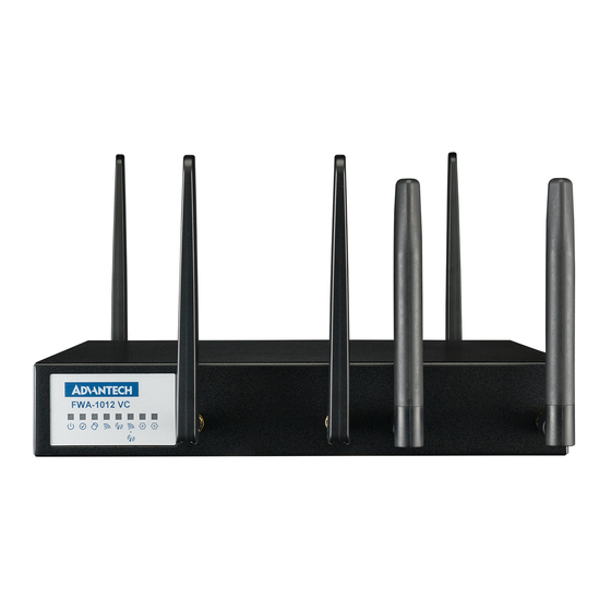
System Outlook 1.2.1 F RONT There are 8 LED indicators and 4 antenna holds in front of the system: Figure 1: System Front View 1.2.2 R EAR , one console port, two USB 3.0 There are power switch locates on back of chassis, lockable DC‐In jack ports, two 1GbE SFP ports, six RJ45 ports, two SIM slots, POE connector and SW defile LED /button the rear side. Figure 2: System Rear View Copyright 2014 Advantech Co. Ltd. All rights reserved. ... -
Page 14: System Layout
System layout System layout as below picture: Figure 3: System Architecture Copyright 2014 Advantech Co. Ltd. All rights reserved. ... -
Page 15: Block Diagram
Block Diagram Figure 4: System Block diagram Copyright 2014 Advantech Co. Ltd. All rights reserved. ... -
Page 16: Component Installation
Component Installation 1.5.1 M /2.5” SSD_HDD/ SSD/ EMORY ODULE ODULE I ODULE This is the drawing of memory location and the stacking of LTE, M.2, POE module, HDD bracket and SSD/HDD into FWA‐1012VC unit. Figure 5: main components on the top side Tighten screw by the instruction on Wifi module in bottom side as below: Figure 6: wifi module location on the bottom side Copyright 2017 Advantech Co. Ltd. All rights reserved. Page 16 ... - Page 17 1.5.1.1 TPM/M.2 SSD/LTE module installation Figure 7: TPM/M.2 SSD/LTE module location 1.5.1.2 2.5” HDD/SSD installation Figure 8: 2.5” HDD/SSD location Copyright 2017 Advantech Co. Ltd. All rights reserved. Page 17 ...
-
Page 18: Rack Mount Kits
1.5.1.3 POE module installation Figure 9: POE module location 1.5.2 R ACK MOUNT 1.5.2.1 2 core SKU rack mount kit installation Figure 10: Rack mount for 2core SKU Copyright 2017 Advantech Co. Ltd. All rights reserved. Page 18 ... - Page 19 1.5.2.2 4/8 core SKU rack mount kit installation Figure 11: Rack mount for 4/8 core SKU 1.5.2.3 8 core SKU with POE rack mount kit installation Figure 12: Rack mount for 8 core SKU with POE Copyright 2017 Advantech Co. Ltd. All rights reserved. Page 19 ...
-
Page 20: Antenna Installation
1.5.3 A NTENNA INSTALLATION Figure 13: Antenna location instruction Copyright 2017 Advantech Co. Ltd. All rights reserved. Page 20 ... -
Page 21: Optimum Mounting Environment
PACE EQUIREMENT Please always keep 20cm space around platform for better thermal dissipation if not running FWA‐1012VC on rack. 1.6.2 T EMPERATURE EQUIREMENT Please make sure environment condition before power on this system: Operating temperature 0 ~ 35 °C (32 ~ 104 °F) with air flow speed 0.7 m/sec Non‐operating Temperature ‐20 ~ 80° C (‐4 ~ 167° F) Relative humidity 95% @ 40° C (non‐condensing) Storage temperature ‐40 ~ 85° C (‐40 ~ 185° F) Copyright 2014 Advantech Co. Ltd. All rights reserved. ... -
Page 22: Operation
2. O PERATION Powering up/down the platform To power up the FWA‐1012VC, please press the power switch button. Before powering down the FWA‐1012VC for any upgrade or maintenance procedures, perform a backup of critical data and programs. Press the Power Switch 1. FWA‐1012 is using Power Switch to power ON/OFF system, when user press power switch as ON ( | ), system will auto power up, , when user press power switch as OFF ( O ), system will force power OFF. 2. Please don’t direct plug or unplug DC Jack when Power Switch sets as ON Copyright 2014 Advantech Co. Ltd. All rights reserved. ... -
Page 23: Booting From Network Via Pxe
Booting from network via PXE To boot an OS via network, please make sure the following BIOS options In the Advanced: Network Stack Configuration Menu is configured properly: BIOS item BIOS item PXE setting CSM Parameters ‐> Network Network Stack Disabled Disabled PXE Do not launch Enabled Disabled PXE Disabled Disabled PXE UEFI Enabled Enabled UEFI IPV4 PXE Disabled Enabled legacy IPV4 PXE Legacy Enabled Enabled legacy IPV4 PXE Table 1: PXE BIOS Options Below are the steps to enable PXE boot. 1. When user sets “ BIOS/ Advanced‐> CSM Parameters ‐> Network” as Legacy to enable PXE ROM function, set it as “Legacy” (IPV4 PXE) function . Copyright 2014 Advantech Co. Ltd. All rights reserved. ... - Page 24 2. When user sets BIOS/ Advanced‐> Network Stack Configuration‐> Network Stack as enabled (default setting is disabled) , It will open UEFI IPV4 PXE support function. 3. Save BIOS and reboot system. The BIOS will show “Checking Media Presence..”, if system is not connected PXE server, it will show “No Media Present..” Copyright 2017 Advantech Co. Ltd. All rights reserved. Page 24 ...
- Page 25 4. User may re‐login in BIOS, choose BIOS/ boot item, it will has “Network Device BBS Priorities” item and set Legacy IPV4 PXE LAN boot sequence priority. And please choose PXE Boot priority as “IBA GE Slot 0A00 v1570” it is on board Mgmt GbE port. Copyright 2017 Advantech Co. Ltd. All rights reserved. Page 25 ...
- Page 26 When User sets “CSM Parameters ‐> Network” as UEFI and “Network Stack” as Enabled, the PXE choosing item is list in “Boot Option Priorities”, please choose Boot Option to set sequence priority of UEFI IPV4 PXE LAN port When UEFI IPV4 PXE doesn’t detect UEFI PXE server, it will return to BIOS manual. PXE boot usually does not allow for OS installation over network as the PXE client will only load a single file from the boot server. Similarly, booting Linux over network is usually a two stage process. In the first step, a boot loader such a grub or mini OS such as SysLinux are loaded via PXE from the boot server. The boot loader or miniOS then load the actual target OS which usually consists of multiple files which decompressed and installed into a RAM disk. The detailed process and required configuration of such network install will heavily depend on the target OS and boot loader / miniOS used. Please refer to the related documentation available. PXE boot requires a DHCP server and a TFTP server in the network to complete. DHCP Server and TFTP server are commonly run on the same machine and collectively referred to as “boot server”. Setting up such a boot server implies a couple of steps. How‐to guides for setting up Linux as PXE boot server are available on the internet, e.g. https://www.debianadministration.org/article/478/Setting_up_a_server_for_PXE_network_booting. Please note that it is recommended to setup a separate network / subnet for network booting as the DHCP required for PXE booting may conflict with existing DHCP servers in your network. Copyright 2017 Advantech Co. Ltd. All rights reserved. Page 26 ...
-
Page 27: Led Behaviour
INDICATOR FUNCTION IN FRONT Figure :SFP connector drawing SFP LED LEFT RIGHT LINK/ACK LINK: Green ACK: SFP1 SPEED: 1G Green Green Blinking LINK/ACK LINK: Green ACK: SFP2 SPEED: 1G Green Green Blinking Table 2: SFP connector LED indication 2.3.3 RJ45 : INDICATOR FUNCTION IN FRONT RJ45 LED LEFT RIGHT SPEED:10M LED OFF LINK/ACK LINK: Green ACK: 1 100M Amber,1G Green Blinking Green SPEED: 10M LED OFF LINK/ACK LINK: Green ACK: 2 100M Amber,1G Green Blinking Green Table 3: RJ45 connector LED indication (Marvell PHY) Copyright 2014 Advantech Co. Ltd. All rights reserved. ... -
Page 28: Rj45 Led Indicator Function W/ Poe In Front
INDICATOR FUNCTION W IN FRONT RJ45 LED LEFT RIGHT SPEED:10M LED OFF LINK/ACK/SPEED LINK: 1 100M Amber,1G 1G/Green,100M/Amber ACK: Green Blinking SPEED: 10M LED OFF LINK/ACK LINK: Green ACK: 2 100M Amber,1G Green Blinking Green Table 4: RJ45 connector LED indication (Marvell PHY) without POE RJ45 LED LEFT RIGHT LINK/ACK/SPEED LINK: 1 POE LED ON: GREEN 1G/Green,100M/Amber ACK: Blinking LINK/ACK/SPEED LINK: 2 POE LED ON: GREEN 1G/Green,100M/Amber ACK: Blinking Table 5: RJ45 connector LED indication (Marvell PHY) with POE Copyright 2017 Advantech Co. Ltd. All rights reserved. Page 28 ... - Page 29 Main Board Connector placement Top side: Figure 14: NAMB‐1012VCMB Connector placement (Top side) Bottom Side: Figure 15: NAMB‐1012VCMB Connector placement (Bottom side) Copyright 2017 Advantech Co. Ltd. All rights reserved. Page 29 ...
- Page 30 CN85 POE POWER CONN SIM CARD CONN CN1 CN88 CN37 CN38 BSCN CONN POE CONN CN86 MINIPICE CONN CN_MINI1 CN_MINI2 CN87 M.2 CONN (B+M KEY 3042 &2280) M.2 CONN (B+M KEY 3042 &2242) CN71 SW3 FPGA switch BSCN switch SW1 CN96 BSCN jumper Table 6: FWA‐1012VC MB Jumper Setting and Connector List Copyright 2017 Advantech Co. Ltd. All rights reserved. Page 30 ...
-
Page 31: Main Board Connector Placement Bios
3. BIOS FWA‐1012VC BIOS is based on AMI’s APTIO BIOS and compliant to the UEFI, SMBIOS and ACPI specifications. The BIOS performs probing, initialization and configuration of the FWA‐1012VC and initializes the OS boot process at the end of POST (Power‐On‐Self‐Test). Regular BIOS output as well as the setup menu are displayed via console port and please note that the FWA‐ 1012VC does not have any on‐board POST Code LEDs. A special POST code adapter is required to retrieve BIOS error codes. All BIOS configuration parameters bare stored in NVRAM, a dedicated section of the BIOS flash chip. Parameters are no longer stored in legacy CMOS RAM by the platform BIOS. I.e. BIOS configuration parameters will not be lost due to an empty battery. BIOS Defaults The BIOS comes with a set of configuration parameters when shipped by Advantech referred to as “Optimized Defaults” or “factory defaults”. The user can change BIOS settings via the setup menu either temporarily or permanently by saving the changes as “User defaults”. The BIOS loads Optimized Defaults by the option “Restore Defaults; and loads User defaults by the option “Restore User Defaults”. If no User defaults have been defined, the BIOS will do nothing. BIOS Setup Menu This section describes the FWA‐1012VC’s UEFI BIOS based on AMI’s APTIO BIOS. Users can modify BIOS settings and control the special features of the FWA‐1012VC using the BIOS setup menu. Please note that Advantech supports shipping the FWA‐1012VC with custom BIOS defaults to simplify the deployment and integration for our customers. Please contact your Advantech representative if you want to receive more information regarding this service. The BIOS Setup Menu can be entered via the BIOS POST screen displayed on the console interface: Figure 15: BIOS POST screen (example) BIOS Setup can be entered by hitting <DEL> or <F2> keys during POST. The BIOS setup menu screens have a few main elements as shown below. The menu bar displays the ... -
Page 32: Main Setup Menu
If security protection has been enabled previously (see chapter 錯誤! 找不到參照來源。), you will be prompted for the BIOS password upon entering the BIOS Setup. After a successful check or if password protection has not been enabled, users will see the Main Setup screen shown below. Users can always return to the Main setup screen by selecting the Main tab. Copyright 2017 Advantech Co. Ltd. All rights reserved. Page 32 ... - Page 33 Figure17: BIOS Setup Main screen The main setup page displays system a summary of system and BIOS configuration and status information. The fields on this page are read‐only except for the System Date and Time setting. Group Setup item Access / Options Description BIOS Vendor Display only American Megatrends Core Version Display only Current AMI BIOS core version in use Compliancy Display only UEFI Spec revision that the BIOS complies to Advantech BIOS Version info BIOS Information EX: mmmm Vx.yz mmmm : model name Project Version Display only X : major version Yz: minor version Build Date & Time Display only Shows BIOS build date and time System Selects the Setup Menu Language. Only English Display only Language is supported on the FWA‐1012VC. Copyright 2017 Advantech Co. Ltd. All rights reserved. ...
- Page 34 Access Level not been enabled, this will default to “Administrator” Table76: BIOS Setup: Main Menu 3.2.1.1 Setting System Time and Date Use this option to change the system time and date. Highlight System Time or System Date using the <Arrow> keys. Enter new values through the keyboard. Press the <Tab> key or the <Arrow> keys to move between fields. The date must be entered in MM/DD/YY format. The time is entered in HH:MM:SS format. Please not that system time and date are set during manufacturing process according to factory’s local time zone. You may need to update system time to reflect the desired time zone when you receive the unit. Copyright 2017 Advantech Co. Ltd. All rights reserved. Page 34 ...
-
Page 35: Platform Setup Menu
Users can display a Platform BIOS Setup option by highlighting it using the <Arrow> keys. The Platform BIOS Setup screen is shown below. The sub menus are described on the following pages. Note: If BMC is Present in the system and Hardware Monitor page will be hidden. Figure 18: Platform Setup Main screen 3.2.2.1 Serial Console This sub menu allows you to change the settings used for the serial console. Note that the serial console is always using COM1 which is connected to the front panel. Copyright 2017 Advantech Co. Ltd. All rights reserved. Page 35 ... - Page 36 COM0 Serial Console Port 9600 / 19200 / Defines the baud rate. Serial Console 38400 / 57600 / Speed 115200 Data Bits 7 / 8 Defines number of data bits in a character. Stop Bits 1 / 2 Defines number of stop bits in a character. None / Even / Odd Parity Defines the parity scheme used. / Mark / Space Flow Control None / Xon/Xoff Defines the flow control scheme. ANSI / VT100 / Select the target terminal emulation type:‐ ANSI to use the Terminal Type VT100+ / Extended ASCII Character Set. Copyright 2017 Advantech Co. Ltd. All rights reserved. Page 36 ...
- Page 37 Recorder Mode and sent as text messages to a remote server. Enabled Disabled / Resolution 100x31 Enables or disables extended terminal resolution Enabled 80x24 / When using Legacy OS, this item specifies the Number of Rows Resolution and Columns supported 80x 25 VT100 /. LINUX / PuTTY Keypad XTERMR6 / SCO / Select Function Key and Key Pad Emulation on PuTTY. ESCN / VT400 This defines how long console redirection will be active: Redirection after Always Enable / “BootLoader” means that legacy console redirection is disabled POST BootLoader before booting into a Legacy OS. “Always Enable” means Legacy console Redirection is enabled permanently. Emergency Management Disabled / Disabled / Enabled serial console interface to the bootloader Services (EMS) menu on modern versions of Microsoft Windows Enabled Console Redirection Table 8: Platform Setup: COM0 Console Redirection Menu Items Copyright 2017 Advantech Co. Ltd. All rights reserved. Page 37 ...
- Page 38 Enabled disabled, the USB EHCI controller will not be Disabled initialized by the BIOS. Legacy USB Support Auto Enables legacy support over USB to support Enabled Keyboard and Mouse Disabled EHCI Hand‐Off Enabled Controls the hand off of XHCI ownership from Disabled BIOS to OS at boot time. Port 60/64 Enabled Enables I/O port 60h/64h emulation Emulation support Disabled Table 9: USB Configuration Menu Copyright 2017 Advantech Co. Ltd. All rights reserved. Page 38 ...
- Page 39 Please note that Trusted Computing support is disabled by default in the factory defaults to save system boot time. If disabled, the Trusted Computing Menu will not display any status information. Figure 21: Platform Setup: Trusted Computing Group Setup item Access / Options Description Security Device Sup Enables or Disables BIOS support for security Enable device. O.S. will not show Security Device. TCG Configuration EFI protocol and INT1A interface will not be Disable available. Table 10: Trusted Computing Menu Copyright 2017 Advantech Co. Ltd. All rights reserved. Page 39 ...
- Page 40 3.2.2.4 NCT7904D HW Monitor The system with NCT7904D HW Monitor , and the BIOS will detect voltages and temperatures and the related information will be shown in the BIOS setup menu as below. Figure 22: Platform Setup: Trusted Computing with TPM2.0 3.2.2.5 Virtualization This sub menu allows you to change the settings used for Virtualization function. Intel® Virtualization Technology for Directed I/O (VT‐d). Thus, BIOS handle virtual functions exposed by PCIe devices in case SR‐IOV is supported, otherwise PCIe devices will be assigned to virtual machines in pass‐ through mode. This applies for all PCIe devices. Copyright 2017 Advantech Co. Ltd. All rights reserved. Page 40 ...
- Page 41 Figure 23: Platform Setup: Virtualization Setup item Access / Options Description Intel Virtualization Enable Enable/Disable Intel Virtualization Technology , take effect after reboot Disable VT‐d Enable/disable Intel Virtualization Technology Enable for Directed I/O (VT‐d) by reporting the I/O Disable device SR‐IOV Support If system has SR‐IOV capable PCIe Devices, this Enable option Enables or Disables Single Root IO Disable Virtualization Support Table 11: Virtualization Menu 3.2.2.6 Platform Management This sub menu allows you to change the settings used for related CPU utilization setting. The default configuration for CPU was optimized setting for getting better performance for networking, so it is not recommend to change it. Copyright 2017 Advantech Co. Ltd. All rights reserved. Page 41 ...
- Page 42 Figure 24: Platform Setup: Platform Management Setup item Access / Options Description EIST Enable or disable BIOS support for Enhanced Intel SpeedStep Technology, When enabled, OS Enable sets CPU frequency according load. When Disable disabled, CPU frequency is set at max non‐ turbo. Max Core C‐State Enable/Disable CPU C6(ACPI C2) report to OS C1, C6 Recommended to be enabled. Package C State Package C State limit. The "waking‐up time" No Pkg C‐State, No limit will be longer if Package C state limit setting is S0Ix, No limit deep C state support. Table 12: Platform Management Menu Copyright 2017 Advantech Co. Ltd. All rights reserved. Page 42 ...
-
Page 43: Hardware Setup Menu
3.2.3 H ARDWARE SETUP MENU This sub menu allows you to change the settings of the Intel chipset. Please note that “chipset” is a legacy term and the related functionality is split over the CPU and PCH portions of the SoC. Similarly, the terms “South Bridge” and “North Bridge” are legacy terms and do not represent the silicon implementation any more. However, those terms are kept consistent with previous products to allow users to navigate more easily. The sub menus are described on the following pages. Figure 25: Hardware Configuration Menu 3.2.3.1 Hardware Setup: CPU Configuration This menu use example of Atom C3000 CPU configuration. Copyright 2017 Advantech Co. Ltd. All rights reserved. Page 43 ... - Page 44 Figure 26: Chipset: Processor Configuration Menu Copyright 2017 Advantech Co. Ltd. All rights reserved. Page 44 ...
- Page 45 Intel VT‐x Technology L1 code Cache L2 Cache Some legacy operating systems are unable to properly deal with the CPUID x86 opcode when Limit CPUID Enabled, Disabled None called using operands greater than 3, Set this Maximum Link to Enabled if you experience just such a problem, otherwise leave this Disabled. Table 13: Processor Configuration Menu Copyright 2017 Advantech Co. Ltd. All rights reserved. Page 45 ...
- Page 46 This menu allows the configuration of the memory controller and related features of the SoC. Figure 27: NorthBridge Configuration Menu Group Setup item Access / Options Description Node 0 Ch 0 Dimm 0 Display only Displays information on the DIMM installed Node 0 Ch 1 Dimm 0 Enable Patrol Scrub Enable Select to enable / disable Patrol Scrub Support DIMM Disable Information Enable Demand Scrub Select to enable / disable Demand Scrub Enable Support Disable Enable Scrambling Select to enable / disable the Scrambler Disable Table 14: Northbridge Configuration Menu Copyright 2017 Advantech Co. Ltd. All rights reserved. Page 46 ...
- Page 47 3.2.3.3 Hardware Setup: South Bridge Configuration This menu contains settings for the South Bridge for related SATA and USB and ACPI setting etc. Figure 28: Hardware Setup: South Bridge configuration Setup item Access / Options Description SATA Configuration N/A Select sub‐menu. ACPI Settings N/A Select sub‐menu. Table 15: Hardware Setup: South Bridge configuration Menu Items Copyright 2017 Advantech Co. Ltd. All rights reserved. Page 47 ...
- Page 48 3.2.3.3.1 South Bridge Configuration: SATA Configuration Figure 29: Hardware Setup: SATA configuration Access / Setup item Description Options SATA Port 0 Display only Show current SATA devices in use on the SATA Port 1 Display only FWA‐1012VC SATA Port 2 Display only Enabled SATA Controller To enable the SATA controller Disabled Table 16: Hardware Setup: SATA configuration Menu Items Copyright 2017 Advantech Co. Ltd. All rights reserved. Page 48 ...
- Page 49 3.2.3.4 ACPI Setting This menu contains settings for the ACPI configuration. Figure 30: Hardware Setup: ACPI configuration Setup item Access / Options Description Enabled Enable ACPI Auto Enable or disable BIOS ACPI auto configuration Configuration Disabled Enabled Lock Legacy Enable lock of legacy resources Resources Disabled Table 17: Hardware Setup: ACPI configuration Menu Items Copyright 2017 Advantech Co. Ltd. All rights reserved. Page 49 ...
-
Page 50: Setup Post & Boot Menu
3.2.4 S POST & ETUP OOT Users can configure the system boot priority settings via the boot page. The default setting of boot priority of boot option #1 is “UEFI: Built‐in EFI Shell”; Users can define the boot priorities based on the application. Figure 31: Boot Configuration Copyright 2017 Advantech Co. Ltd. All rights reserved. Page 50 ... - Page 51 Setup Prompt Timeout 1 Number of seconds to wait for setup activation key. Bootup NumLock State On Select the keyboard NumLock state. Quiet Boot Disabled Enables or disables Quiet Boot option. Network Stack Disabled Enables or disables boot via Network (PXE) Boot Option Priority User Defined Sets the system boot order. CSM16 Parameters N/A Select sub‐menu. CSM Parameters N/A Select sub‐menu. Table 18: Boot Configuration 3.2.4.1 Compatibility Support Module (CSM) Configuration This submenu allows users to configure the support for legacy BIOS mechanisms and option ROMs. Figure 32: Post & Boot Setup: CSM Configuration Menu Copyright 2017 Advantech Co. Ltd. All rights reserved. Page 51 ...
- Page 52 Setup item Access / Options Description CSM Support Enabled Enables or disables the Compatibility Support Module. Disabled Boot option filter UEFI and Legacy This item allows to control the execution of Legacy Only legacy and UEFI compliant Option ROMs UEFI Only Network Storage Do not launch This item allows a more granular control of UEFI OptionROM execution depending of the type of Video extension device. Legacy Other PCI device ROM Table 19: CSM Configuration Menu 3.2.4.2 CSM16 Configuration This submenu allows users to configure the support for legacy BIOS CSM16 Figure 33: CSM16 Configuration Copyright 2017 Advantech Co. Ltd. All rights reserved. Page 52 ...
- Page 53 Setup item Access / Options Description GateA20 Active UPON REQUEST ‐ GA20 can be disabled using Upon Request BIOS services. ALWAYS ‐ do not allow disabling GA20; this option is useful when any RT code is Always executed above 1MB Option ROM Force BIOS Set display mode for Option ROM Messages Keep Current Table 20: CSM16 Configuration Menu 3.2.4.3 Security Setup “Administrator Password” allows users to configure the system so that a password after being installed is required each time the system boots, and/or an attempt is made to enter the Setup program. Figure 34: Administrator Setup Note: If set the “Password Check” is [Setup], then this only limits access to Setup and is only asked for when entering Setup. Copyright 2017 Advantech Co. Ltd. All rights reserved. Page 53 ...
- Page 54 If set the “Password Check” is [Always], then this is a power on password and must be entered to boot or enter Setup. In Setup the User will have Administrator rights. The password length must be in the following range: Minimum length: 3 Maximum length: 20 Copyright 2017 Advantech Co. Ltd. All rights reserved. Page 54 ...
- Page 55 Exit setup after saving the changes. Does not update User Exit defaults. Discard Changes and Exit setup without saving any changes. Exit None Save Changes and Reset system after saving the changes. Does not update User Reset Defaults. Discard Changes and Reset system without saving the changes. Reset Save Changes Save Changes made so far to any of the setup options. Save Options Discard Changes Discard Changes made so far to any of the setup options. Restore Defaults Restores the BIOS factory defaults to all the setup options. Copyright 2014 Advantech Co. Ltd. All rights reserved. ...
- Page 56 Save as User Defaults Saves the Current BIOS Settings as User Defaults. Restore User Defaults Restores the User defaults to all the setup options. This option allows you to override the specified boot order and Boot Override UEFI: < boot device> use a different boot device for the next boot. Table 21: Save & Exit Menu Options Copyright 2017 Advantech Co. Ltd. All rights reserved. Page 56 ...
- Page 57 PPENDIX CKNOWLEDGEMENTS Award is a trademark of Award Software International, Inc. IBM, PC/AT, PS/2 and VGA are trademarks of International Business Machines Corporation. Intel® and Pentium® are trademarks of Intel Corporation. Microsoft Windows® is a registered trademark of Microsoft Corp. All other product names or trademarks are properties of their respective owners. Copyright 2017 Advantech Co. Ltd. All rights reserved. Page 57 ...
- Page 58 The international organization responsible for managing and maintaining the ASF specification. DTS Digital Thermal Sensor ECC Error Correcting Code EEPROM Electrically Erasable Programmable Memory. A non‐volatile memory located on the LAN controller that is directly accessible from the host EHCI Enhanced Host Controller Interface. EMI Electromagnetic Interface ESD Electrostatic Discharge GB/s Gigabytes per second(1000Mbytes per second) Gb/s Gigabits per second(1000Mbits per second) GT/s Giga‐transfers per second I2C Inter‐integrated circuit IEEE Institute of Electrical and Electronics Engineers. IIO Integrated I/O Controller. ILM Independent Loading Mechanism. IMC Integrated Memory Controller. IOV I/O virtualization. IPMB Intelligent Platform Management Bus IPMI Intelligent Platform Management Interface Copyright 2017 Advantech Co. Ltd. All rights reserved. Page 58 ...
- Page 59 QPI Quick Path Interconnect. A cache‐coherent, link‐based interconnect specification for Intel Processors, chipsets, and I/O bridge. RAID Redundant Array of Inexpensive Disks or Redundant Array of Independent Disks RANK A unit of DRAM corresponds to four to eight devices in parallel, ignoring ECC. These devices are usually, but not always, mounted on a single side of a DDR3 DIMM. RDIMM Registered dual In‐line Memory Module. RGMII Reduced gigabit media independent interface RTC Real Time Clock Sandy Bridge‐EP Intel’s 32‐nm processor design, follow‐on to the 32‐nm Sandy Bridge processor design. Processor SATA Serial ATA. SAS Serial Attached SCSI SCI System Control Interrupt. Used in ACPI protocol. SDRAM Synchronous Dynamic Random Access Memory SerDes Serializer and De‐Serializer Circuit SGMII Serialized Gigabit Media Independent Interface SIU Serial I/O Unit SIW Serial I/O and Watchdog Timer SKU Stock Keeping Unit Copyright 2017 Advantech Co. Ltd. All rights reserved. Page 59 ...
- Page 60 SMBus System Management Bus. A two‐wire interface through which various system components may communicate. SPD Serial Presence Detect SPI Serial Peripheral Interface. TAC Thermal Averaging Constant TBD To Be Defined. TDP Thermal Design Power TPM Trusted Platform Module Turbo Boost Intel Turbo Boost Technology is a way to run the processor core faster than the Technology marked frequency. UART Universal Asynchronous Receiver/Transmitter UHCI Universal Host Controller Interface USB Universal Serial Bus USB DOM USB disk‐on‐module QAT Intel® QuickAssist Technology Copyright 2017 Advantech Co. Ltd. All rights reserved. Page 60 ...
Need help?
Do you have a question about the FWA-1012VC and is the answer not in the manual?
Questions and answers