Table of Contents
Advertisement
Advertisement
Table of Contents

Related Manuals for Rotem Platinum Pro


Summary of Contents for Rotem Platinum Pro
- Page 1 Platinum Pro Controllers Installation Manual P/N: 110472...
- Page 2 Neglecting to provide such a backup will be regarded as the user’s willingness to accept the risk of loss, injury and financial damage. In no event will Rotem be liable to a user or any third party for any direct, indirect, special, consequential or incidental damages, including but not limited to any damage or injury to...
-
Page 3: Table Of Contents
Table of Contents Front Matter ....................4 Introduction ........................4 Conventions ........................4 Contact Information......................4 Document Information ...................... 4 Precautions ....................5 Grounding .......................... 5 Filtering ..........................5 Checking the Battery Level ....................5 Frequency Inverters ......................5 Technical Details ..................6 Specifications ........................ -
Page 4: Front Matter
Rotem will not accept responsibility for damage resulting from the use of this manual. Rotem also reserves the right to make changes and improvements to its products and/or the associated documentation without prior notice. -
Page 5: Precautions
2 PRECAUTIONS ● Grounding ● Filtering ● Checking the Battery Level 2.1 Grounding ● Always connect temperature and sensor shields to earth ground. Avoid mixing high voltage wiring with sensor and low voltage wiring. ● Keep the controller as far as possible from heavy contactor boxes and other sources of electrical interference. -
Page 6: Technical Details
3 TECHNICAL DETAILS ● Specifications ● Layout 3.1 Specifications Input Power Voltage 100 – 240 VAC 2.2 Amp, 50-60Hz Relay Loads 30.0 Amps Active Load; 2 HP Inductive Load, 250 Volts, non-Fused for C-P3-NO-RC-30A relay cards 20.0 Amps Active Load; 1 HP Inductive Load, 250 Volts, non-Fused for C-P3-NC-RC-30A relay cards 20.0 Amps Active Load;... -
Page 7: Layout
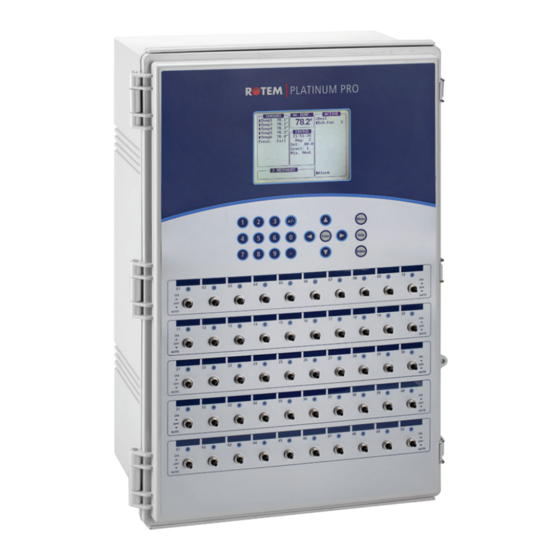
3.2 Layout The following illustration displays the main elements in Platinum Pro units. Figure 1: Platinum Pro Layout NOTE: Figure 1 is an example layout. Each installation can differ. Platinum PRO supports: ● Analog input, digital input, analog output cards ●... -
Page 8: Site Preparation
4 SITE PREPARATION The following sections detail the initial steps required when placing the Platinum controllers. 4.1 Mounting 1. Remove the mounting plates (x4) and screws (x8) from the plastic bag. 2. Fasten the mounting plates to the corners of the controller using four screws. -
Page 9: Drilling
2. Drill a hole on the bottom side of the controller box. Verify that the high voltage cables being used fit through the hole properly. NOTE: Rotem recommends drilling at least two (2) holes, placed as close to the front edge as possible (to avoid crowding the wiring). Platinum Controllers | 6.0X... - Page 10 Figure 3: Drilling on the Bottom 3. Clean the holes from plastic shards. Verify that rims of holes are smooth. Figure 4: Hole locations Platinum Controllers | 6.0X...
-
Page 11: High Voltage Wiring
5 HIGH VOLTAGE WIRING This section details how to wire the controller’s high voltage wiring: WARNING! Before beginning, disconnect the power supply! CAUTION Only a qualified electrician may perform the electrical installation! ● Power Supply, page 11 ● Relay Wiring, page 12 ●... -
Page 12: Rplp Wiring
5.1.1 RPLP Wiring The following section details how to wire an RPLP Lighting Protector unit to the power supply. CAUTION Install the RPLP, 230 V only (part number P-RPLP-1-V2)! On the RPLP's protected side: 1. Connect the RPLP grounding wire to the Platinum grounding terminal. 2. - Page 13 Figure 7 key Phase common 2. Connect the relay cables to each inlet/curtain/device. Figure 8: Relay Cable Connections Figure 8 key Cable to device Phase common 3. On the sticker below each relay, write the name of the device connected to the relay. 4.
-
Page 14: Winch Card Relay Wiring
This procedure details how to connect Winch Cards to the inlets. Winch cards simplify backup (opening air sources such as inlets) in a power/heating event. NOTE: Winch Cards are optional. Users employing an RBU-27 do not require Winch Cards. Rotem recommends that users employing an RBU-5 or RBU-3 install Winch Cards. NOTE: Use relays 7 –... -
Page 15: Completing The Wiring
5.4 Completing the Wiring ● Tie the cables together with tie wraps and route them as shown (through the high voltage wiring holes drilled as shown in Drilling, page 9). Figure 12: Wrapping the Cables Platinum Controllers | 6.0X... -
Page 16: Low Voltage Wiring
6 LOW VOLTAGE WIRING The following section details the: ● Analog Card DIP Switches ● Analog Input Wiring Diagram for Temperature Sensors ● Analog Input Wiring Diagram for CO2 and Light Sensor ● Analog Input Wiring Diagram for Potentiometers ● Analog Input Wiring Diagram for Humidity Sensors Platinum' analog input card (P/N: C-P3-RAIC12) supports up to 12 analog devices: temperature, light, CO2, and humidity sensors, wind direction detectors, and potentiometers. -
Page 17: Analog Input Wiring Diagram For Temperature Sensors
6.1.2 Analog Input Wiring Diagram for Temperature Sensors ● Connect the temperature sensor to an input and COM port. Terminals 1 - 8: These inputs support temperature sensors only. ● IN1 – IN4: These are optional temperature sensor inputs (turn DIP Switch 4 (T) on each set as required). -
Page 18: Analog Input Wiring Diagram For Potentiometers
Figure 14: Light and CO2 Sensors Wiring Figure 14 key Shield wire connected to grounding strip 6.1.4 Analog Input Wiring Diagram for Potentiometers 1. Connect each potentiometer (10 - 20 KOhm) to an input, a COM, and 3.3V port. 2. IN1 – IN4: Turn on DIP Switch 3 on each set as required. Figure 15 shows an example potentiometer wiring. -
Page 19: Analog Input Wiring Diagram For Humidity Sensors
Figure 15 key Shield wire connected to grounding strip 6.1.5 Analog Input Wiring Diagram for Humidity Sensors 1. Connect each humidity sensor to input, a COM, and +12V port. 2. IN1 – IN4: Turn on DIP Switch 2 on each set as required. Figure 16 shows an example humidity sensor wiring setup. - Page 20 Figure 17: Weather Station Wiring Figure 18: Weather Station Analog Input Card Figure 19: Weather Station Digital Input Card Platinum Controllers | 6.0X...
-
Page 21: Digital Input Wiring
3.3V Ground strip 6.3 Digital Input Wiring Platinum PRO has a Digital Input Card (P/N: C-P3-RDIC12) with 12 inputs which are used to measure digital sensors. Each input requires an input and COM port. ● It is possible to connect the common of several sensors to the same connector. However Rotem recommends spreading the commons in an even manner. -
Page 22: Analog Output Wiring
6.4 Analog Output Wiring Platinum PRO has an analog output card (C-P3-RAOC10) with 10 outputs, used to drive external units controlled by 0 – 10 VDC. The analog outputs card consists of surge and lightening protection circuits and does not require external protections. -
Page 23: Alarm Card Wiring
Rotem’s Alarm Card (C-PP-P3-ALARM) provides integrated lightning protection for a single alarm device of up to 430 Volts DC. If you need to lightening protection for more than one device, use Rotem’s P-RLVP to protect low voltage devices or the RPLP for line voltage devices. - Page 24 Figure 23: C-P3 Siren Wiring Diagram Figure 23 key 12V battery NOTE: If you need to protect more than one device, use Rotem’s P-RLVP to protect low voltage devices or the RPLP for line voltage devices. Platinum Controllers | 6.0X...
-
Page 25: Communication Card Wiring
6.6 Communication Card Wiring The communication option provides a means to connect a personal computer locally or remotely by modem. Connection to the computer is via a communication device. Figure 24: Controller– MUX RS-232 Wiring Figure 24 key Controller communication card See Approximate Distances and Baud (C-P3-232ISO485) Rate, page 17... - Page 26 Figure 25: Controller – Communicator Isolated RS-485 Wiring Figure 25 key Communicator External Box Shield cable Box communication ports Other controllers Ground strip. To prevent ground loops, See Approximate Distances and Baud connect the shield wire at one end only. Rate, page 17 Isolated controller communication card (example) (C-P3-485ISO485)
Need help?
Do you have a question about the Platinum Pro and is the answer not in the manual?
Questions and answers