Sign In
Upload
Download
Table of Contents
Contents
Add to my manuals
Delete from my manuals
Share
URL of this page:
HTML Link:
Bookmark this page
Add
Manual will be automatically added to "My Manuals"
Print this page
×
Bookmark added
×
Added to my manuals
Manuals
Brands
Rotem Manuals
Controller
AC-2000 SE
Installation manual
Rotem AC-2000 SE Installation Manual
Pig controllers
Hide thumbs
1
2
3
4
5
6
7
8
9
10
11
12
13
14
15
16
17
18
19
20
21
22
23
24
25
26
27
28
29
page
of
29
Go
/
29
Contents
Table of Contents
Troubleshooting
Bookmarks
Table of Contents
Table of Contents
1 Front Matter
Introduction
Conventions
Contact Information
Document Information
2 Precautions
Grounding
Filtering
Checking the Battery Level
Frequency Inverters
3 Technical Specifications
5 Amp Fuse
4 Installation
Mounting the Unit
AC-2000 Plus Wiring
Transformer
AC-2000 Plus Board Layout
AC-2000 Plus Relays
Voltage Regulator
AC-2000 Plus High Voltage Wiring (Relays)
AC-2000 Plus Terminals
AC-2000 Plus Low Voltage Wiring (Terminals)
AC-2000 Plus Communication
4.3.1 Ac-2000 Board Layout
AC-2000 SE Wiring
AC-2000 Board Layout
AC-2000 SE Relays
AC-2000 SE High Voltage Wiring (Relays)
AC-2000 SE Terminals
AC-2000 SE Low Voltage Wiring (Terminals)
MUX / RCLP Wiring
5 Configuration
Configuration (Menu 91)
Ventilation Table (Menu 92)
Relay Layout (Menu 93)
Manual Relay Operation
Relay Record
Sensor Layout (Menu 94)
Setup Curtains (Menu 95)
6 Troubleshooting Guide
7 Electrical Grounding
Ground Rods
Ground Wire
Ground Clamps
What Should be Grounded
Lightening Protection
Power Line Protection
Communication Line Protection
8 Appendix: Installing a CO2 Sensor
Low Voltage Wiring
Configuring the CO2 Sensor
Advertisement
Quick Links
1
Introduction
2
Configuration (Menu 91)
3
Ventilation Table (Menu 92)
4
Relay Layout (Menu 93)
Download this manual
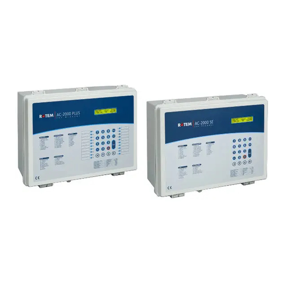
AC-2000 SE and PLUS
Pig Controllers
Installation Manual
P/N: 110118
Table of
Contents
Previous
Page
Next
Page
1
2
3
4
5
Advertisement
Chapters
Table of Contents
3
4.3.1 Ac-2000 Board Layout
12
Table of Contents
Need help?
Do you have a question about the AC-2000 SE and is the answer not in the manual?
Ask a question
Questions and answers
Related Manuals for Rotem AC-2000 SE
Controller Rotem AC-2000 PLUS Installation Manual
Pig controllers (29 pages)
Controller Rotem Platinum plus Installation Manual
(51 pages)
Controller Rotem Platinum Plus User Manual
(61 pages)
Controller Rotem SuperGuard Installation Manual And User's Manual
(52 pages)
Controller Rotem Platinum plus User Manual
(95 pages)
Controller Rotem Platinum JUNIOR User Manual
(87 pages)
Controller Rotem RLD 7.2 Installation And User Manual
Two channel light dimmer (22 pages)
Controller Rotem Platinum Pro Installation Manual
(26 pages)
Controller Rotem SuperGuard Installation And User Manual
Precision controller system (63 pages)
Controller Rotem platinum junior xl User Manual
(91 pages)
This manual is also suitable for:
Ac-2000 plus
Table of Contents
Save PDF
Print
Rename the bookmark
Delete bookmark?
Delete from my manuals?
Login
Sign In
OR
Sign in with Facebook
Sign in with Google
Upload manual
Upload from disk
Upload from URL


Need help?
Do you have a question about the AC-2000 SE and is the answer not in the manual?
Questions and answers