Table of Contents
Advertisement
Quick Links
Advertisement
Table of Contents

Related Manuals for Rotem SuperGuard


Summary of Contents for Rotem SuperGuard
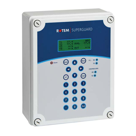
- Page 1 SuperGuard and Piguard 80 Installation Manual and User Guide 110085...
- Page 2 Neglecting to provide such a backup will be regarded as the user’s willingness to accept the risk of loss, injury and financial damage. In no event will ROTEM be liable to a user or any third party for any direct, indirect, special, consequential or incidental damages, including but not limited to any damage or injury to...
-
Page 3: Table Of Contents
3.3.1 SuperGuard ........................7 3.3.2 Piguard ........................... 8 Getting Started ..................... 9 10 Step Installation Guide ....................9 SuperGuard Keyboard ....................10 SuperGuard Main Screen ....................11 Hotkeys ..........................12 SuperGuard Setup..................14 CONTROL ....................16 Temp Curve ........................16 Min. - Page 4 12.7.2 Installation and Electrical Connections ................. 47 12.8 Mechanical Installation Guide ..................48 12.9 Environmental Protection ....................48 12.10 Metal Sheet Assembly Diagram ..................49 12.11 SuperGuard/Piguard Network Connection ..............50 12.12 Piguard Wiring Diagram 1 ....................51 12.13 Communication Wiring Diagram ..................52...
-
Page 5: Front Matter
Read this manual before operating your Rotem product. Using this equipment for any other purpose or in a way not within the operating recommendations specified in this manual will void the warranty and may cause personal injury. -
Page 6: Precautions
CAUTION Check the battery once a year. The output must be 2.7 volts (minimum). Authorized personnel only must replace the battery if the output is below the minimum required level or every five years. SuperGuard and Piguard 80 | 1.04... -
Page 7: Introduction
4x20 character LCD that provides display feedback on the programming and device status. The SuperGuard communicates with Piguard units to access history, collect events and alarms for each and all relevant data up to 100 days. -
Page 8: Piguard
• On/Off/Auto override switches • Static pressure control (optional) • 4 Analog output (0 - 10 volts) • Variable speed fan output with bypass • Water, feed, and humidity control • Automatic calibration of curtains SuperGuard and Piguard 80 | 1.04... -
Page 9: Getting Started
4 GETTING STARTED The following sections explain the basic concepts in using the SuperGuard and Piguard controllers. 10 Step Installation Guide This is a quick 10 step guide that explains basic concepts needed for a proper system installation: Hardware Installation: Read all technical specs and use the wiring diagrams, from page 46 in this manual, to install all hardware. -
Page 10: Superguard Keyboard
The Number keys are selected when a numeric choice is done Numeric Pad and when numbers should be selected. Moreover, those keys are used for Hot Keys purposes. Delete The 'Delete' key erases typing mistakes. SuperGuard and Piguard 80 | 1.04... -
Page 11: Superguard Main Screen
Current ventilation level. NOTE: The main screen shows basic information regarding rooms controlled by the SuperGuard, depending on what equipment is plugged in. Other parameters like static pressure (PRESS), outside temperature (OUT), level, message and offset are also shown on the main screen when they are plugged in. -
Page 12: Hotkeys
CURTAIN STEPS CURT.1 CURT.2 CURT.3 CURT.3 TUNNEL INLET Hot key 6: System Status This screen shows if humidity treatment is ON/OFF, if the cycle is ON/OFF and how many seconds left for the current cycle. SuperGuard and Piguard 80 | 1.04... - Page 13 • Minimum value measured on that day ('Min' column) • Average value calculated on the measured temperatures through the whole day ('Avg' column) • Maximum value measured on that day ('Max' column) TEMPERATURE ROOM 21.4 23.5 24.5 21.8 24.6 24.7 SuperGuard and Piguard 80 | 1.04...
-
Page 14: Superguard Setup
To reach the SuperGuard Setup screen: 1. Go to Room key. 2. Press '0' and "Enter" from any of the main screens. The SuperGuard setup is a procedure for customizing the SuperGuard and Piguard units to match the system. SuperGuard ===COMM.===... - Page 15 (maximum of 10). Make sure you define the Piguards' numbers in the following order without skipping digits; meaning: 1,2,3,4... If TOTAL ROOMS not set this way, the SuperGuard does not detect any Piguards. After defining the number of Piguard controllers, the SuperGuard begins a search to find the controllers defined.
-
Page 16: Control
Alarm low 0 - 40° C (without floating point) Alarm high 0 - 40° C (without floating point) M in. Max. Level 2 7 B Soft Minimum By Day By Day Min Cold Min Warm SuperGuard and Piguard 80 | 1.04... - Page 17 Min Cold Min Warm System parameters -> Min/Max Level control - DSFT (Soft Min by days) Soft Min temp - Out (Control by outside temperature) Soft Min Band - 4° F (Differential below heat temperature) SuperGuard and Piguard 80 | 1.04...
-
Page 18: Humidity
• To select the type of minimum/maximum go to system parameters and change the level control (see page check this). H umidity 2 8 B HUMIDITY Target Delay (minute) Duration (sec) Band (%) Below Heat • Target: Set the humidity level to this target. SuperGuard and Piguard 80 | 1.04... -
Page 19: Static Pressure
• Pre Open: Time setting for curtains to open before fans activate. This is to make sure the curtains are open before fan activity. • Alarm Minimum Level: From what level you wish to activate low static pressure alarm. SuperGuard and Piguard 80 | 1.04... -
Page 20: System Parameters
Min Fan 3 Spd% use the soft minimum. Min Fan 4 Spd% Default: OUT • Soft Temp Band: Diff below heat temperature to set temperature at which to enforce low temperature minimum SuperGuard and Piguard 80 | 1.04... - Page 21 ‘Cool Pad #’ relays. Default: 2.0 ==FOGGER== • From Level: From what ventilation level to begin fogger operation. 0 is no operation. Default: 0 • Temp Band: See cool pad above. Default: 1.0 SuperGuard and Piguard 80 | 1.04...
-
Page 22: Control Mode
• All alarms are disabled. • A flashing massage appear while displaying temperature. • "E" In Piguard and "Empty House" in SuperGuard. Setting controller to Normal or Empty mode inserts an event to History/Event table. SuperGuard and Piguard 80 | 1.04... -
Page 23: Device
VENT LEVELS 12345678 Diff The SuperGuard provides up to 30 programmable ventilation levels. The usual way to program them is to start the first level with the least amount of air to be used. The full circles represent continuous fan operation. - Page 24 Tunnel Fans Diff SuperGuard and Piguard 80 | 1.04...
-
Page 25: Var. Fan Levels
If set on 20%, the fan will operate at 20% of the full power during off time in the cycle and increases to 100% during the on time. 7.3 Curtain Levels CURTAIN (%) Crt. 1 Crt. 2 Crt. 3 Crt. 4 Tun. inlet …30 Curtain Level Example Curtain (% Open) Level Tunnel Inlet Levels 1 thru SuperGuard and Piguard 80 | 1.04... -
Page 26: Circulation Fan
• To Level: Up to what level operate this application. If any of the above four definitions is set to 0, the circulation fan operates at any time or level according to the differential. SuperGuard and Piguard 80 | 1.04... -
Page 27: Cool Pad
The cooling system turns on the amount above specified in the column ‘Diff’ and turns off when the temperature drops the amount specified in the band. Stop Activate Band Temp. Activate Temp Band (Diff) Stop SuperGuard and Piguard 80 | 1.04... -
Page 28: Foggers
Set the on/off times according to growth day, there are up to five programmable lines. F eed 3 9 B FEED # Day From 10:00 12:00 14:00 16:00 Set the time period that feeding takes place. There are up to five programmable lines. SuperGuard and Piguard 80 | 1.04... -
Page 29: Extra System
7.10 Time Clocks TIME CLOCKS From 10:00 12:00 14:00 16:00 This is a simple device definition table with operation time and cycle. There are up to five functions (relays) available to program as time clocks. SuperGuard and Piguard 80 | 1.04... -
Page 30: Variable Heat
• Maximum Heat: Maximum heaters operation for safety measures. This parameter refers to both Var. Heat 1 and Var. Heat 2. Default: 100% • End Day: Set the last growth day for the Variable Heaters operation. Default: 0 SuperGuard and Piguard 80 | 1.04... -
Page 31: Management
• New Group: To start a new group, select YES under new group fragment and the controller automatically increases the group number by one and set growth day to 1. NOTE: When starting a new group, history is deleted!!! • Group No.: You can manually change the group number. SuperGuard and Piguard 80 | 1.04... -
Page 32: Alarm Setting
Variable Speed Stop (Yes/No): When in low temperature alarm, decide whether to keep variable speed in minimum operation or totally shut down the function. ==WATER & FEED== Min/Max Water/Hour: A quantity of water per hour, above which alarm activates. SuperGuard and Piguard 80 | 1.04... -
Page 33: Alarm Reset
There are two types of data plugs, Regular and Gold. The Gold Data Plug can store up to eight different settings. By naming each setting differently you can easily write/read data from the plug to the controller and vice versa. Read from Plug? NO◄ SuperGuard and Piguard 80 | 1.04... - Page 34 Before loading the setting, you can view setting name and software version for this setting. Press Enter to load the data on the controller. To cancel reading from this setting, press MENU. READING FROM PLUG PLEASE WAIT SuperGuard and Piguard 80 | 1.04...
-
Page 35: Write To Plug
On the Gold Data Plug, select NO SETTING to create a new setting or overwrite an existing one. ENTER SETTING NAME Name: Room No. 1 To Change ARROWS OK ENTER, Abort MENU Press Enter to load data to the plug. SuperGuard and Piguard 80 | 1.04... -
Page 36: History
Sensors: Data collection for minimum, maximum and average in temperature and humidity for the last 100 days. W ater 5 2 B WATER DAILY • Day: Growth day. • Daily: Daily consumption. • %Change: % Change from previous day. SuperGuard and Piguard 80 | 1.04... -
Page 37: Feed
• Total: Mortality total since growth day one. 9.6 Heater HEATER ROOM #01 Heat 1 Heat 2 01:05 00:00 00:42 00:00 The history heater shows the amount of HH:MM the heater was on that day. SuperGuard and Piguard 80 | 1.04... -
Page 38: Alarm
14. Sn.1 Out Rng- sensor out of range 15. Sn.2 Out Rng 16. Sn.3 Out Rng 17. Sn. Not Def- sensor not defined 18. Aux Alarm- auxiliary alarm. 19. Press. Fail 20. Low S. Press. 21. High S. Press. SuperGuard and Piguard 80 | 1.04... -
Page 39: Event
The events table is similar to the alarms table but without icons. For example: In the table above “menu #11” means that there was a change of settings in CONTROL menu 1, Temp Curve table. SuperGuard and Piguard 80 | 1.04... -
Page 40: Calibration
10.4 W ater & Feed 6 1 B Water/feed Water per pulse 0.1 Feed per pulse The water and feed system operates on a pulse counting method. Enter the amount of feed/water per pulse. SuperGuard and Piguard 80 | 1.04... -
Page 41: Installation
• Foggers • Curt. 1-4 open • Curt. 1-4 close • Tunnel open • Tunnel close • Inlet open • Inlet close • Light • Feed • Circulation • Extra system 1-3 • Timer 1-5 SuperGuard and Piguard 80 | 1.04... -
Page 42: Sensors Layout
1 Var. Heat 1 0.0 10.0 2 Var. Heat 2 0.0 10.0 3 Var. Fan 3 4 Var. Fan 4 Use the Round Arrows key to run through the list of outputs and press enter to select an output. SuperGuard and Piguard 80 | 1.04... -
Page 43: Variable Speed Fan
Average: The average definition refers to the average temperature, according to the sensor defined. An empty line defined for a certain sensor, indicates that the sensor will operate according to the average temperature definition. SuperGuard and Piguard 80 | 1.04... -
Page 44: Curtain Setup
60 60 Inlet 60 60 Curtain Setup tells the controller how fast your curtains and side inlets move. It needs this information to properly calculate automatic inlet advance as well as inlet and curtain positions. SuperGuard and Piguard 80 | 1.04... -
Page 45: Piguard
4. Press Select to move through the sensors and the arrows to change temperatures NOTE: Calibration of humidity sensor is done exactly the same way; the only difference is that instead of measuring temperature, the humidity is measured by an external humidity sensor. SuperGuard and Piguard 80 | 1.04... -
Page 46: Test
92.5 x 7 3x 36 Ambient Climate Operating Temperature Range 0º to + 50º C Storage Temperature Range -10º to + 70º C Indoor Applications CAUTION The equipment is designed for use in indoor applications only! SuperGuard and Piguard 80 | 1.04... -
Page 47: Piguard Installation Guide
Otherwise, the acetic acid will attack the metal parts, including circuitry. • Drill cable entry holes on the bottom of the box only. SuperGuard and Piguard 80 | 1.04... -
Page 48: Mechanical Installation Guide
12.9 E nvironmental Protection 7 7 B Recycle raw materials instead of disposing as waste. The controller, accessories and packaging should be sorted for environmental-friendly recycling. The plastic components are labeled for categorized recycling. SuperGuard and Piguard 80 | 1.04... -
Page 49: Metal Sheet Assembly Diagram
1. Drill holes in the three designated areas located in the back of the controller. 2. Mount the controller using the three screws provided in the small plastic bag. 3. Place the provided plastic caps on the screws. SuperGuard and Piguard 80 | 1.04... -
Page 50: Superguard/Piguard Network Connection
12.11 S uperGuard/Piguard Network Connection 7 9 B SuperGuard and Piguard 80 | 1.04... -
Page 51: Piguard Wiring Diagram 1
12.12 Piguard Wiring Diagram 1 Analog Output, Power, Potentiometer, Relays, Variable speed, RHS-2 SuperGuard and Piguard 80 | 1.04... -
Page 52: Communication Wiring Diagram
12.13 C ommunication Wiring Diagram 8 1 B SuperGuard and Piguard 80 | 1.04...
Need help?
Do you have a question about the SuperGuard and is the answer not in the manual?
Questions and answers