Table of Contents
Advertisement
Quick Links
Advertisement
Table of Contents

Related Manuals for ATEN Master View ACS-1712

Summary of Contents for ATEN Master View ACS-1712
- Page 1 2001-07-05...
- Page 2 NOTE: This equipment has been tested and found to comply with the limits for a Class B digital device pursuant to Subpart J of Part 15 of the FCC Rules. These limits are designed to provide reasonable protection against harmful interference in a residential installation.
- Page 3 The complete Master View ACS-1712 / ACS-1714 package consists of: One ACS-1712 or ACS-1714 KVM Switch One Power Adapter One User Manual Check to make sure that the unit was not damaged in shipping. If you encounter a problem, contact your dealer.
-
Page 4: Table Of Contents
Limited Warranty ..........20 ACS-1712 / ACS-1714 User Manual... -
Page 5: Features
KVM Switch - USB Port combination functions as a USB Hub, it allows two (ACS-1712 ) or four (ACS-1714 ) computers to access and share all the connected USB peripherals. Not only does this eliminate the need to purchase a separate USB hub, it also eliminates the need to purchase separate stand-alone peripheral sharers - such as print servers, modem splitters, etc. - Page 6 Dual Function KVM-USB Switch One Console Controls 2 (ACS-1712 ) or 4 (ACS-1714 ) Computers and Two Additional USB Devices USB Keyboard and Mouse Independent Switching of KVM and Additional USB Ports - Control one Computer while Printing From a Second Computer at the Same Time Fully Compliant with the USB 1.1 Specification...
- Page 7 Use of substandard cables may damage the connected devices or degrade overall performance. For optimum signal integrity and to simplify the layout, we strongly recommend that you use the following high quality CS cables: Part No. 2L-1201U [1.2M]; or Part No. 2L-1202U [1.8m]. ACS-1712 / ACS-1714 User Manual 2001-07-05...
-
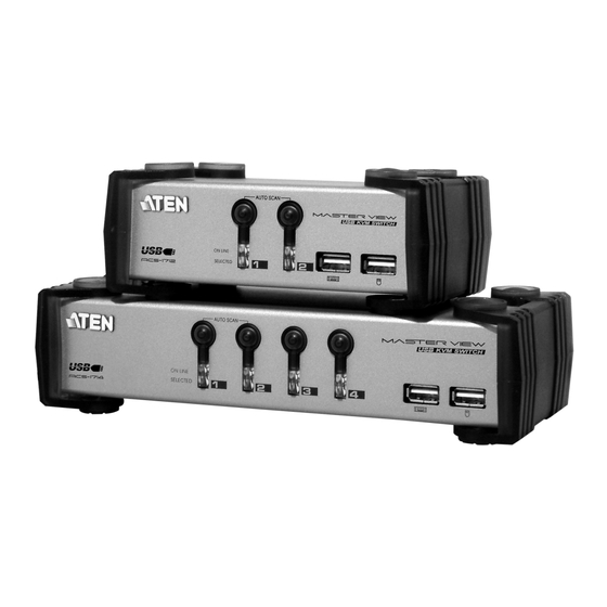
Page 8: Front View
3. USB Ports Your USB keyboard and USB mouse plug in here. * The front view diagram is for the ACS-1714. The layout of the ACS-1712 is exactly the same, except that it only has two port selection switches. ACS-1712 / ACS-1714 User Manual... -
Page 9: Power Jack
The HDB-15 male connectors (bottom row) are for the video cables that link to the computers to plug into. * The rear view diagram is for the ACS-1714. The layout of the ACS-1712 is exactly the same, except that it only has 2 CPU ports instead of 4. - Page 10 Consult your dealer for technical details, if necessary. To set up your Master View ACS-1712 / ACS-1714 installation do the following: 1. Plug your USB keyboard and USB mouse into the USB Ports located on the unit’s front panel.
- Page 11 2. If the unit is operating under external power, unplug the power adapter cable. 2. Wait 10 seconds, then plug the Master View ACS-1712 / ACS-1714 unit back 3. After the Master View unit is up, Power On the computers.
- Page 12 The Master View ACS-1712 / ACS-1714 provides three methods to obtain instant access to any computer on your installation: Manual; Hotkey; and OSD. Manual Simply press the appropriate Port Selection Switch on the Master View’s front panel. After you press the switch, the Selected LED lights to indicate that the port is currently selected.
- Page 13 Each CPU port on a Master View installation is assigned a single digit number (1 or 2 for the ACS-1712; 1 to 4 for the ACS-1714). The Port ID of a computer is derived from the CPU Port number it is connected to.
- Page 14 Switches access to the USB peripherals to computer [2] [Ctrl]+[Shift]+[Alt]+[F3]* Switches access to the USB peripherals to computer [3] [Ctrl]+[Shift]+[Alt]+[F4]* Switches access to the USB peripherals to computer [4] * Master View ACS-1714 only Action ACS-1712 / ACS-1714 User Manual 2001-07-05...
- Page 15 The OSD always starts with the highlight bars at the last position selected no matter which selection method was used (Push Button Switches, Hotkeys or OSD. The next two sections explain how to navigate using the OSD. ACS-1712 / ACS-1714 User Manual NAME WARREN TINA...
- Page 16 After executing any action, you automatically go back to the menu one level above. Note: CPU Port access andUSB peripheral access can be assigned independently. One computer can have the console focus while another one has access to the USB peripherals. ACS-1712 / ACS-1714 User Manual 2001-07-05...
- Page 17 Next one on the installation. If you are at the last computer, you cycle back to the first one. Move the Highlight Bar to the port you want then press [Enter]. An icon appears before the choice to indicate that it is the currently selected one. ACS-1712 / ACS-1714 User Manual Explanation 2001-07-05...
- Page 18 Hotkey sequence for any Port ID that has an active computer attached. 2. As each computer is accessed, an ID display to indicate that it is being accessed under Auto Scan Mode. appears in front of the Port ACS-1712 / ACS-1714 User Manual 2001-07-05...
- Page 19 Unlocking the Console. If a password has been set,you must provide the password in order to Lock / Unlock the Console. If no password has been set, pressing [Enter] will Lock / Unlock the Console. ACS-1712 / ACS-1714 User Manual appears 2001-07-05...
-
Page 20: Set Password
Scroll Lock option should be used. The factory default settings are as follows: Setting Display Duration Always On Display Mode The Port Number plus the Port Name Scan Duration 5 Seconds Default ACS-1712 / ACS-1714 User Manual 2001-07-05... - Page 21 Note: To modify or delete a previous password, access the Password function as in Steps 1 and 2, then use the backspace or delete key to erase the individual letters or numbers. ACS-1712 / ACS-1714 User Manual 2001-07-05...
-
Page 22: Operation
[Ctrl]+[Shift]+[Alt] combination, key in the Port ID and press [Enter] within one second for each keystroke. Mouse not Improper mouse Unplug the mouse connector from the Console responding. reset. Mouse Port, then plug it back in. Action ACS-1712 / ACS-1714 User Manual 2001-07-05... -
Page 23: Port Selection
0 - 80% RH Housing Metal Weight 490g Dimensions (L x W x H) 130 x 74.5 x 42mm ACS-1712 / ACS-1714 User Manual ACS-1714 4 (Orange) 4 (Green) 4 x USB Type B 4 x HDB -15 male DC 5V; 1.25W max. -
Page 24: Limited Warranty
The direct vendor also reserves the right to revise or update the device or documentation without obligation to notify any individual or entity of such revisions, or update. For further inquires please contact your direct vendor. ACS-1712 / ACS-1714 User Manual 2001-07-05...
Need help?
Do you have a question about the Master View ACS-1712 and is the answer not in the manual?
Questions and answers