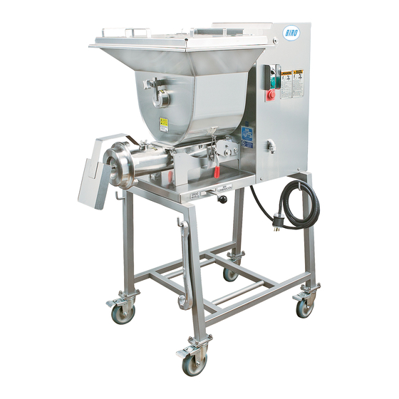
BIRO MINI-32 Operating And Service Manual
Automatic feed mixer grinder
Hide thumbs
Also See for MINI-32:
- Operating and service manual (24 pages) ,
- Operating and service manual (28 pages)
Table of Contents
Advertisement
Quick Links
Advertisement
Table of Contents

Related Manuals for BIRO MINI-32


Summary of Contents for BIRO MINI-32
- Page 1 Model MINI-32 AUTOMATIC FEED MIXER GRINDER Operating and Service Manual IMPORTANT NOTICE This Manual contains important safety instructions which must be strictly followed when using this equipment. Item No. 32313-299 Form No. Mini-32-3-19-9 B...
-
Page 3: Table Of Contents
TABLE OF CONTENTS: PAGE NOTICE TO OWNERS AND OPERATORS ..........SAFETY TIPS . -
Page 4: Notice To Owners And Operators
No one should use or service this machine without proper training and supervision. All operators should be thoroughly familiar with the procedures contained in this Manual. Even so, BIRO cannot anticipate every circumstance or environment in which its products will be used. You, the owner... -
Page 5: Safety Tips
NEVER Alter This Machine From its Original Form as Shipped From Factory. DO NOT Operate Machine With Missing Parts. • PROMPTLY REPLACE Any Worn or Illegible Warning Labels. • ALWAYS Read Operation and Service Manual BEFORE Operating, Cleaning, or Servicing. • USE ONLY BIRO Parts and Accessories Properly Installed. -
Page 6: Installation
NEVER Operate Without all Warning Labels Attached and Owner/Operator Manual Available to the Operator. • USE ONLY BIRO Parts and Accessories Properly Installed. UNCRATING AND SET UP 1. Read this Manual thoroughly before installation and operation. Do not proceed with installation and operation if you have any questions or do not understand anything in this Manual. -
Page 7: Motor Wiring And Electrical Requirements
8. The size of the electrical wiring required from the power source to the mixer grinder/chopper is a MINIMUM OF No. 12 WIRE. 9. The BIRO Manufacturing Company is not responsible for permanent wiring, connection or installation. NOTE TO OWNER AND ELECTRICIAN: IF THIS MACHINE IS NOT CORD... -
Page 8: Pre-Operation
15. Check placement of all warning labels and be sure anyone who is to operate this MINI-32 MIXER GRINDER has read and fully understands the manual. Machine is now ready for trained operators to process product. -
Page 9: Parts Location
PARTS LOCATION AUGER DRIVE ENGAGE LEVER ENGAGED DISENGAGED... -
Page 10: Operation
OPERATION ROTATING GRINDING AUGER & ROTATING MIXING PADDLE TO AVOID SERIOUS PERSONAL INJURY • ONLY Properly Trained Personnel Should Use This Equipment. • NEVER Place Hands into Machine Input or Output Openings. • NEVER Open Machine During Operation. • DO NOT Wear Gloves While Operating. •... -
Page 11: Cleaning
Electrical Components. • ALWAYS Thoroughly Clean Equipment at Least Daily. CLEANING THE MINI-32 MIXER-GRINDER l. Disconnect mixer grinder from power-source and perform lockout/tagout procedures. 2. Remove grinding bowl end ring, breaker plate, knife and grinding auger. 3. Remove mixing paddle, hopper and grinding bowl assembly from machine (see instruction on page 9). -
Page 12: Removal & Installation Instructions
REMOVAL & INSTALLATION INSTRUCTIONS PADDLE REMOVAL: Remove mixing paddle by first locating and lifting up on the hopper lock down clamps releasing them from the hopper. Next loosen the paddle lock knob (four point knob located at the front of the hopper). Then turn the locking lever clockwise approximately ¼... -
Page 13: Maintenance & Lubrication
• PROMPTLY REPLACE Any Worn or Illegible Warning Labels. • USE ONLY GENUINE BIRO Parts and Accessories Properly Installed. LUBRICATION 1. MOTOR: The grinder motor has pre-lubricated, sealed motor bearings. 2. ROLLER CHAIN AND DRIVE SPROCKETS: The main drive chain has been pre-lubricated at the factory to protect it against dirt and moisture. - Page 14 LUBRICATION CONTINUED FOR GEAR REDUCERS 1. Factory Filling The speed reducer is filled with Mobil Glygoyle 460 polyglycol (PAG), to the proper level for the standard mounting position. The oil level should be checked and adjusted (if necessary) prior to operation, using the oil level plug provided and while the unit is oriented in its operating position.
- Page 15 GEAR REDUCERS (Item No. 63070, up to Serial No. 560) (Item No. 63070G, Serial No. 561 and up) LUBRICATION AND MAINTENANCE 63070/63070G LUBRICANTS FOR GEAR WORM REDUCERS The precision-made gears and bearings in gear speed reducers require high-grade lubricants of the proper viscosity to maintain trouble-free performance. For best results, use lubricants on the following chart for worm gear reducers.
-
Page 16: Parts List Diagrams
MOTOR DRIVE COVER AND HOPPER COVER pulled out for clarity Fig. Item No. Description 63035S 42MC-Y73 Stn Stl hopper cover & arm assembly Start button, Green 63035 Hopper cover & arm assembly 56125 Legend plate (controls) 63082 Lid safety arm weldment 42MC-Y74 Stop button, Red 62182... - Page 17 MOTOR DRIVE COVER AND HOPPER COVER Fig. Item No. Description 63169 Sleeve bushing washer 62182 Sleeve bushing, hinge EMG92032 Washer, outside hinge lid arm HHS083S Hex head cap screw, ⅜-16 x 1¾”, SS 311-1 Rubber bumper AN05S Acorn nut, 8-32, high crown, SS 63035S-PX Hopper cover &...
- Page 18 ELECTRICAL BOX 16 17 20 21 11 12 Fig. Item No. Description Fig. Item No. Description 63094-1 H281EE-51 Electrical box weldment, s/n 500 on Overload, B18K-K, 4-6.3 A 63027-A Bushing, multi hole, .25 DIA 63028 Din rail, 2⅜” long 63027-B RHS060S Cord grip, 90°, ½”...
- Page 19 MOTOR-DRIVE UNIT COMPONENTS Fig. Item No. Description Fig. Item No. Description 15026-02 63049 Double roller chain, 49” Timing belt 15029 Double chain master link 63055 Cart assembly w/ casters 20050-10 #40 Roller chain, 80 pitch 63057 Table top leg, (Optional) 20050-01 #40 Roller chain master link, #40-C/L 63070...
- Page 20 TRANSMISSION TRANSMISSION MOUNTING ASSEMBLY MOUNTING ASSEMBLY Fig. Fig. Item No. Item No. Description Description Fig. Item No. Description Fig. Item No. Description 20665 63081-02 Key, ¼ x ¼ x 1⅛” Bowl support bracket, RH 20665 Key, 1/4 x 1/4 x 1-1/8 S.S. Bowl support bracket, LH 63081-01 20665-01...
- Page 21 BOWL & WORM ASSEMBLY Fig. Item No. Description 63017 Bowl hook stud, 2 required 54278-CTN Auger assembly 54278-CTNS Optional SS, Auger assembly HK48 Knife drive pin HK48S Knife drive pin, SS 54278B Square drive insert 54278BS Square drive insert, SS 54278C Auger shear pin FHS33S...
-
Page 22: Fasteners & Locations
FASTENERS & LOCATIONS Base Plate (63005) to Cart Assembly (63055) Motor (63099 or 63099-3 or 63099-4) to Shaft Item No. Bearing Retainer-rear (63008 or 63008-1) Item No. 4 ea. HHS090S Hex head screw, ⅜-16 x 2½”, SS 4 ea. LW20S Lock washer, ⅜”, SS 4 ea. -
Page 23: Electrical Schematics
Before Serial No. 783... - Page 24 Serial No. 783 to 2132...
- Page 25 Serial No. 783 to 2132...
- Page 26 Serial No. 2133 on...
- Page 27 Serial No. 2133 on...
-
Page 28: Footswitches, Pneumatic & Electric
PNEUMATIC FOOT SWITCH #56304 Part No. DESCRIPTIONS 56300BEL Bellow, Replacement 56300C Guard Only 56300K-CPB CPB Coupling Metal Body-Male 56303 Foot Switch w/Male Coupling 56304 Foot Switch Assembly Complete ⅜ HHS004S Hex Head Screw, #8 - 32 x HN05S Hex Nut #8 - 32 LW03S Lock Washer #8... - Page 29 ELECTRIC FOOT SWITCH...
-
Page 30: Safety Label Locations
SAFETY LABEL LOCATIONS WIRED FOR 1 PHASE #42MC-666 WIRED FOR BIRO 3 PHASE #42MC-665 WIRED FOR 208 VOLTS #42MC-656 BIRO WIRED FOR #VT460S 220 VOLTS #H653-E #H653-SP #42MC-657 NOT TO SCALE #53783 GRIND MUELA COMBINACION 63176 63177 #63177 #BES16971 #63176... -
Page 31: Operator Signature Page
OPERATOR’S SIGNATURE PAGE WARNING READ AND UNDERSTAND THIS ENTIRE MANUAL BEFORE SIGNING BELOW MY SIGNATURE ATTESTS THAT I HAVE COMPLETELY READ AND UNDERSTAND THIS MANUAL. I REALIZE THAT THIS MACHINE, IF OPERATED CARELESSLY, CAN CAUSE SERIOUS INJURY TO MYSELF AND OTHERS. NAME (PRINT) SIGNATURE SUPERVISOR’S... -
Page 32: Limited Warranty
BIRO is not responsible for service charges or labor required to replace any part covered by this limited warranty or for any damages resulting from misuse, abuse, lack of proper or recommended service.
Need help?
Do you have a question about the MINI-32 and is the answer not in the manual?
Questions and answers