
Related Manuals for Balter IP-D1231VR

Summary of Contents for Balter IP-D1231VR
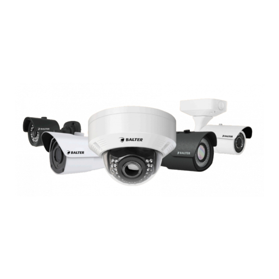
- Page 1 IP Cameras Manual Version 1.0.2 IP-D1231VR IP-T1241Gr IP-D1443VR IP-T1441GR IP-B1403 IP-T3443R IP-MT1441GR IP-T3443GR...
-
Page 2: Table Of Contents
2.1.1 Draft 8.1.2.8 Shutter Mode 45 2.1.2 Components IP-D1231VR 5 8.1.2.9 Shutter Time 45 2.1.3 Installing the IP-D1231VR 6 8.1.2.10 Defog 46 2.1.4 Dome Camera Diagram 3-Axis Control 7 8.1.3 Privacy Masking 46 2.1.5 Manually adjusting Zoom and Focus 7 8.1.3.1... -
Page 3: About This Manual
Diphenylether (PBDE), Deca-BDE und max. 0,01% des Gewichtes für Cadmium) Here by Balter GmbH confirms that to its knowledge all products (unless explicitly stated otherwise) sold by Balter Secu- rity GmbH fulfill the requirements of the EU directive 2011/65/EU. These products are compatible with the current RoHS requirements for the 7 substances (max 0.1% by weight in homogeneous materials for lead, mercury, hexavalent chromi-... -
Page 4: Safety Information
1.4 Safety Information Warning This symbol represents possible dangers, risks or circumstances requiring special attention. The user must comply with the handling-, maintenance-, and repair instructions Beware The lightning symbol in a triangle represents dangerous currents close to the product casing that can seriously harm an persons. 1.5 Safety Instructions Never touch current-carrying electrical parts. -
Page 5: Drafts And Installation
2. Drafts and Installation 2.1 IP-D1231VR 2.1.1 Draft Casing Screw (Torx T15) Lens Dome Power Connector Video Connector 2.1.2 Components IP-D1231VR Name Function Part Interior Cover Protects the lens and movable parts. Day/Night Sensor Activates the IR-LEDs. IR-LEDs Enable videosurveillance in no-light conditions. -
Page 6: Installing The Ip-D1231Vr
2.1.3 Installing the IP-D1231VR Please Note -Only attach the camera to surfaces that can hold the fivefold weight of the camera. -Use cables in flawless condition only. Creased cables can damage the camera and a FIRE HAZARD! - -Make sure that no persons are in the danger zone during installation. -
Page 7: Dome Camera Diagram 3-Axis Control
2.1.4 Dome Camera Diagram 3-Axis Control The camera‘s direction can only be adjusted when the camera is attached to the ceiling. You can pan the camera to the left and the right, tilt it up or down and turn the lens. Tilt Turn Nerver touch the camera‘s lens! -
Page 8: Inserting An Sd Card (Dome Camera)
Zoom: Loosen the upper screw with a screwdriver. Move the component by dragging the screw to the left or Take care not to remove it completely. right until the desired zoom level is reached. Verify the settings via a monitor or smartphone. Focus: Loosen the lower screw using a screwdri- Move the component by dragging the screw to the left or ver. -
Page 9: Ip-D1443Vr
2.2 IP-D1443VR 2.2.1 Draft Casing Screw Lens Dome Power connector Video connector Audio in (red) Audio out (white) Alarm conectors 2.2.2 Components IP-D1443VR Part Name Function Interior cover Protects the lens and movable parts. Day/Night Sensor Activates the IR-LEDs. IR-LEDs Enables videosurveillance in no-light conditions. -
Page 10: Installing The Ip-D1443Vr
2.2.3 Installing IP-D1443VR Please Note: -Only attach the camera to surfaces that can hold the fivefold weight of the camera. -Use cables in flawless condition only. Creased cables can damage the camera and are a FIRE HAZARD! -Make sure that no persons are in the danger zone during installation. Opening the camera Attention: Do not touch the camera‘s lens! -
Page 11: Ip-B1403
2.3 IP-B1403 2.3.1 Draft Bezeichnung Funktion Bauteil Lens To be mounted to the case Case Contains the elctronics Auto-Iris Cable Transmits video from the lens to the camera Enables the connection of external devices to the camera RS-485 Inputs Audio In Jack for connecting a microphone Ethernet Interface Connects the camera via an ethernet cable to a network... -
Page 12: Assembling The Box Camera
2.3.2 Assembling the box-camera 1. Remove the protective cap from the camera‘s lens 2. Do NOT touch the camera‘s lens connector and quickly connector by turning it counterclockwise. continue with step 3. 3. Connect the Auto-Iris cable to the corresponding jack 4. -
Page 13: Ip-T1241Gr/Ip-T1441Gr
2.4 IP-T1241GR/IP-T1441GR 2.4.1 Draft Bezeichnung Bauteil Lens Casing Video Connector Power Connector Mounting foot Screw A Screw B Screw C Sunprotector Screw Sunprotection... -
Page 14: Montage Ip-T1241Gr/Ip-T1441Gr
2.4.2 Installing IP-T1241GR/IP-T1441GR The camera is weather resistant according to IP66. However, this does not apply to cables and connectors. We recommend installing the camera below the ridge line to prevent moisture entering the camera & Hold the camera to the desired position and mark Drill holes at the marked positions and insert dovels. -
Page 15: Montage Im Außenbereich
2.4.3 Outdoor Installation When installing the camera in outdoor areas, the cables must be sealed using butyl tape to prevent moisture entering the camera. -Connect all cables. -Seal each cable link with butyl tape. -Seal all cable links with the butyl tape. -
Page 16: Ip-Mt1441Gr
2.5 IP-MT1441GR 2.5.1 Draft Function Item Lens Day/Night Sensor IR LEDs Video Connector Power Suppy Mounting Foot Lock Ring Sun Protection screw Sun Protection... -
Page 17: Installing The Ip-Mt1411Gr
2.5.2 IP-MT1411GR Installation The camera is watherproof according to IP66. However, this does not apply to the cables nor the connectors. We recommend installing the camera below the eave to prevent moisture entering the camera via the connectors. & Hold the camera against the wall and mark bore- Drill the holes and insert dovels. -
Page 18: Ip-T3443R/Ip-T3443Gr
2.6 IP-T3443R/IP-T3443GR 2.6.1 Draft 2.6.2 Components IP-T3443R/IP-T3443GR Bezeichnung Bezeichnung Bauteil Bauteil Junction Box Allen screw Recessews with 2 Allen screws Joint Sun cover screw Power connection Sun cover Ethernet connector Lens Alarm connector Recesses for boreholes Analogue video output Cable entry with rubber protection microSD cardslot Lower cable entry Control for zoom/focus... -
Page 19: Installing The Ip-T3443R/Ip-T3443Gr
2.6.3 IP-T3443R/IP-T3443GR Installation Remove both Allen screws at the lower end of the Lift the camera and pull it down to remove the junction box. spigots (10) from the groove (9). & Hold the junction box against the wall and mark the Drill holes and insert dovels. - Page 20 If you work with cables running behind a wall, cut If you are working cables that are not running 5.1. 5.2. open the cable entry with rubber protection (7) and behind a wall, remove the screw at the lover edge of run the cables through it.
- Page 21 Reattach the camera to the junction box by putting To adjust the camera vertically and turn it around the spigots (10) into the grooves (9), then insert and its own axis loosen the screw on the joint (11) und tighten the Allen screws (12). adjust the camera as desired.
-
Page 22: Connecting The Camera To A Pc In A Local Network
3. Network Diagram 3.1 Connecting the camera to a PC in a local network Camera Internet Switch Camera External PC Local PC DDNS Server 3.2 Directly connecting the camera camera to a DHCP based DSL-/cable modem Internet DSL-/Cablemodem Camera External PC DDNS Server 3.3 Directly connecting the camera to a PPPoE modem Internet... -
Page 23: Using The Ip Finder Tool To Find Cameras In A Local Network
4. Using the IP Finder Tool to find cameras in a local network 4.1 IP Finder 1. ID Number 2. Device Type 3. IP Address 4. MAC Address 5. Firmware Version 6. Network settings - Input fields for IP Address, Subnet Mask, Gateway, DNS Server 7. -
Page 24: Searching For Devices In A Lan
4.2 Searching for Devices in a LAN Click „Refresh list of devices“. All found devices will be displayed in the list. 4.3 Change Network Settings • Enter a user name and a passoword into the fields „Login“ and „Password“ • Click on a device in the list. -
Page 25: Webinterface Of Ip Cameras
5. Webinterface of IP cameras 5.1 Supported Browsers Windows: Internet Explorer Firefox Not supported: EDGE, Chrome macOS: Safari 5.2 Installing the Web Plug-In When accessing the web interface for the first time, you will need to install the web plug-in. 5.2.1 The installation page will be displayed when the surveillance site is accessed for the first time. - Page 26 5.2.3 Click „Yes“ 5.2.4 Click „Install“, to confirm the installation. 5.2.5 Restart the webbrowser and enter the IP camera‘s IP address into the URL bar. If the installation was successful, you will see the login interface.
-
Page 27: Login Interface And Language Selection
5.3 Login Interface and Language Selection 5.3.1.Language Selection Click and select your language. 5.3.2 Login Enter the user name and password. Generic login data: User Name: admin Password: admin... -
Page 28: Live View
5.4 Live View Main Menu Live Live view Playback Playback window (will be displayed only when the camera has an SD cardslot) Remote Settings Camera Settings Local Settings Location for exported videos and snapshots Logged in user, Interface- and Plugin version Log out Live view menu MainStream... -
Page 29: Image Settings
Status display Storage medium missing Continous recording Motion recording Line crossed Perimeter Object appeared/disappeared Camera was covered 5.4.1 Image settings Click to open the image settings menu. Brightness Contrast Saturation Sharpness... -
Page 30: Lens Zoom/Focus Controls
5.4.2 Lens zoom/focus controls This function is only available with cameras with an motorzooom lens. Click to open the lens control menu. Zoom- und focus controls Hold + or - to zoom in or out. The camera starts the autofocus once the zoom button is released. -
Page 31: Saving Images/Videos
5.4.3 Saving images/videos 5.4.3.1 Run the browser as an administrator To save images, the browser must be ran as an administrator. Rightclick the Internet Explorer or Firefox icon and select „Run as administrator“ Select the storage location in the menu „Local Settings“ . 5.4.3.2 Saving images Click , to save an image. -
Page 32: Playback
6. Playback Click „Playback“, to be taken to the playback window. 6.1.1 Calender Select the date in the calendar. Selected day Recordings available No recordings available... -
Page 33: Recording Type
6.1.2 Recording type Use the menu „Type“ to select a recording type. Only recordings of the selected types will be displayed in the timebar, other recordings will be hidden. 6.1.3 Search After selecting the date und recoding type, click „Search“. The recordings of the selected day will be shown. -
Page 34: Controlbar
6.1.5 Controlbar Start/pause playback Stop playback Picture for Picture Slow playback. (From 1/2x to 1/8x) Fast forward. (From 2x bis 8x) Audio On/Off Aspect Ratio: Original/Stretched Export video segment. Videoabschnitt wird direkt auf Ihrem Rechner gespeichert. Note: To save videos, the webbrowser must be ran as an administrator. Snapshot: Note: To save images, the webbrowser must be ran as an administrator. -
Page 35: Export
7. Export Using the export function you can save video segments and complete videos on your computer. Please note: To use this function you must run your webbrowser in administrator mode. Rightclick the Internet Explorer or Firefox icon and select „Run as aministrator“. Use the menu „Local Settings“... -
Page 36: Settings
8. Settings Use the menu „Settings“ to access the camera‘s settings. Display settings: *Live – Camera name and time *Image settings – Image settings *Privatzonen – Privacy masking *ROI – Region of interest Recording settings: *Settings – General recording settings *Schedule - Scheduled recording Network Settings: *Network settings –... - Page 37 Occurence settings: *Motion – Motion detection *Alarm – Alarm connectors *Cover detection – Optical tamper detection Device settings: *SD Card – format SD card, overwriting. *Audio – Audio on/off *Log - Log System settings: *Date/Time – Set date and time *User –...
-
Page 38: Display Settings
8.1 Display settings 8.1.1 Live Name Camera name Show channel Show camera name in camera image Time Show time and date in camera image Flicker Flicker settings. Transparency Set transparency of the displayed camera name and date/time... -
Page 39: Image Control
8.1.2 Image Control 8.1.2.1 Day/Night Mode Auto In low-light conditions, the camera automatically changes into monochrome mode. Color only The image always stays in color B/W only The image always stays monochrome Day/Night delay The minimal time (in seconds) between switching from color to B/W mode. -
Page 40: Flip, Mirror, Corridor
8.1.2.2 Flip, Mirror, Corridor Normal image Flipped image Mirrored Mirrored and flipped Corridor 8.1.2.3 BLC Backlight compensation BLC off BLC on... -
Page 41: Noise Filter
8.1.2.4 Noise filter Noise filter off Noise filter on Please note: A high noise filter level makes dark images clearer and removes image noise. However, a high noise filter level can lead to ghosting and less sharpness. -
Page 42: Wdr (Wide Dynamic Range)
8.1.2.5 WDR (Widy Dynamic Range) WDR provides a clear image in situations with strong light/dark contrasts or backlighting. . Outdoor WDR off WDR on . Indoor WDR off WDR on... - Page 43 WDR Level WDR Medium WDR High Please note: WDR can cause image noise.
-
Page 44: Agc (Amplification)
8.1.2.6 AGC (Amplification) AGC amplifies light in low-light conditions AGC low AGC medium AGC high Please note: A high AGC level can lead to more image noise. -
Page 45: White Balance
8.1.2.7 White balance Use white balance for an accurate display Options: Auto Automatic Manuell Manually correct colors Indoor Only for indoor areas 8.1.2.8 Shutter-mode Auto Automatic shutter time. Limited by shutter time settings Manual Camera uses set shutter time. 8.1.2.9 Shutter time The shutter time determines how long the camera‘s shutter stays open and how much light hits the image sensor. -
Page 46: Defog
8.1.2.10 Defog Defog uses algorithms to display a clear image even in foggy conditions. Defog off Defog on 8.1.3 Privacy masking Privacy masking allows you to hide areas from recording. For each camera 4 areas can be designated freely - these areas will neither be recorded, nor shown in live view. -
Page 47: Activating And Selecting Masking Zones
8.1.3.1 Activating and selecting masking zones Activate „Privacy Zone“. Designate the desired areas. Click „Save“... -
Page 48: Deleting Masking Zones
8.1.3.2 Deleting Privacy zones Click on a Privacy Zones. This zone will be marked yellow. Click „Delete“ Click „Save“ 8.1.4 ROI ROI optimizes bandwith usage without quality losses in important areas. With ROI you can monitor different parts of an image in different qualities. Stream Type ROI for Mainstream or Substream. -
Page 49: Deactivating Roi Areas
Please note: If you want to select the areas with the best quality, you need to change the image quality for the rest of the image to „worst quality“. You can change the video quality for the rest of the image vie „Network -> Video transmission“. 8.1.4.2 Deactivate ROI areas Select the desired „Area ID“... -
Page 50: Schedule
8.2.2 Schedule In this menu you can schedule recordings. 8.2.2.1 Creating a schedule 1. Each color represents a recording type and each box represents a 30 minute period . Choose the desired recording type. 2. You can create a separate recording schedule for each day. If you want to copy the created schedule to all other days, click „Copy“. -
Page 51: Network
8.3 Network 8.3.1 Network Settings DHCP: IP Settings will be automatically carried over from the router. Static: Manual entry of IP, Subnet mask, Gateway and DNS Client Port Port for CMS, App and Video transmission HTTP Port Port for Web Interface Mobile Port Port for App IP Adresse... -
Page 52: Video Streaming
8.3.2 Video Streaming Via the menu „Video Streaming“ you can adjust parameters like bitrate, resolution for each stream. 3 Streamtyps are supported: Main Stream – High resolution Sub Stream – Medium resolution Mobile Stream – Low resolution You can switch between these streamtypes during live transmission. Main Stream, Sub Stream, You can adjust the settings for each stream type separately. - Page 53 Bitrate Control VBR – Variable bitrate When using VBR, you can select a video quality level. VBR is a video coding method that controls the bitrate corresponding to move- ments and the amount of detail in a scene. In a simple scene, for example an empty hallway, a high compression will be used, the bitrate and the transmitted data will be lower, resulting in less band- with usage.
-
Page 54: Email
8.3.3 Email This function notifies you via email in case of an occurrence. Contact you email provider to learn your SMTP data. Email Activate/deactivate email. SSL Encryption SMTP Port SMTP Port. Standard Ports: 25,587,465 SMTP Server SMTP Server Sender Sender email address Sender Password Password Receiver... -
Page 55: Ddns
8.3.4 DDNS Dynamic DNS or DDNS updates domains in the Domain Name System (DNS) dynamically. For example a camera will change its domain entry quickly after a change in its IP address. This way a camera or NVR is always available under the same domain name, even if the user doesnt know its current IP address. The supported services are www.dyndns.org and www.no-ip.com. -
Page 56: Rtsp
8.3.6 RTSP The RTSP allows you to view your camera‘s livestream on RTSP capable devices or software (for example the free VLC media player). RTSP Streams Main Stream: rtsp://IP:554/ch00/A Sub Main Stream: rtsp://IP:554/ch00/1 Mobile Stream: rtsp://IP:554/ch00/2 RTSP streams are password protected. Username and password are identical to the camera‘s user name and password. -
Page 57: Alarm
8.4 Alarm 8.4.1 Motion Detection Activate Activate/Deactivate motion detection Sensititvity Adjust sensitivity in 7 levels Activate recording Activate recordings onto an SD card Afteralarm recording Recording time after a movement Alarm output Activate Alarm Output if a motion is detected Activation time Activation time of the alarm output Send email... -
Page 58: Alarm Output
8.4.2 Alarm Output Alarm input and output settings Using the alarm inputs you can connect external devices (for example motion detectors) to the camera. Alarminput Activate/deactivate alarm onput Activation time Activation time for alarm outputAktivierungszeit für Alarmausgang Email versenden Email versenden Alarm Ausgang Alarm-Ausgang aktivieren Aufnahme aktivieren... -
Page 59: Device
8.5 Device 8.5.1 Micro SD Card This function is only accessible when a camera with an SD cardslot is connected.. Here you can format the SD card, change the overwriting mode and view the card‘s status. Please note: The status display works only with continuous recording, not with moreion recording.ung. 8.5.2 Audio This function is only available for cameras with an audio input. -
Page 60: Log
8.5.3 Log The log gives you an overview of every incident relating the camera. Choose the type of log via „Major Type“ aus. Select the begin- and end time. Click „Search“. 8.6 System 8.6.1 Date/Time System Time Time and date Date Format DD/MM/YY(Day/Month/Year), MM/DD/YY(Month/Day/Year), YY/MM/DD (Year/Month/Day) -
Page 61: Users
8.6.2 Users In this menu you can change passwords, assign rights and activate/deactivate users. There are 2 user types. A maximum of 7 users can be registered. admin Administrator, wields all rights and cannot be deactivated. user User Every user can be assigned following rights: Parameter Settings Change settings Live... -
Page 62: Info - P2P Qr Code
8.6.3 Info – P2P QR Code In this menu you can see the devices‘ QR-Code and system information 8.7 Advanced 8.7.1 Firmware Update In this menu you can update your camera‘s firmware. Click „Scan“ Navigate to a „Firmware“ file Click „Upgrade“... -
Page 63: Load Default
8.7.2 Load Default Reset all parameters Click “All“ than click “Save” Reset select parameters Select the desired parameters, than click “Save” 8.7.3 Maintain Auto Reboot Select “Enable” to automatically restart the camera once a week Reboot Manually reboot the camera... -
Page 64: Analytics
8.8 Analytics A permanent, automated analysis of image contents saves time and efficiently monitors the surroundings. 8.8.1 Perimeter Intrusion Recognizes intrusion into a user-defined perimeter. Switch Activate/deactivate perimeter intrusion Sensitive Select Sensitivity in 4 levels Scene Indoor/Outdoor Send E-mail Sends an email in case of an perimeter intrusion Rule Number Select up to 4 perimeters Rule Switch... -
Page 65: Setting Perimeter Areas
8.8.1.1 Setting Perimeter Areas 1. Select “Enable” in the menu “Switch”. 2. Select „Outdoor“ or „Indoor“ in the menu „Scene“ 3. Select „Send Email“, if you want to receive email notifications. 4. Select „Activate“ in the menu „ Menü Regel aus. 5. -
Page 66: Changing Perimeter Areas
8.8.1.2 Changing Perimeter Areas 1. Each Perimeter Area is labeled 1-4 2. Click the desired area to select it. The selected area will turn red. Drag the corners to adjust the area. 8.8.1.3 Deleting a Perimeter Area 1. Select an area and click „Delete“. -
Page 67: Line Crossing
8.8.2 Line Crossing Recognizes the crossing of a line. Switch Activate/deactivate function Latch Time Alarmtime Post Recording Recording after occurence Sensitive Select Sensitivity (4 levels) Scene Outdoor/Indoor Enable I/O Out Activate Alarm Output Send Email Send an Email with an image Record Activate recordind onto SD card Rule Number... -
Page 68: Defining Lines
8.2.2.1 Defining Lines 1. Select „Activate“ in the menu „Switch“ 2. Choose between „Outdoor“ or „Indoor“ in the menu „Scene“ 3. Toggle „Send Email“ if you want to receive Email notifications. 4. Select „Enable“ in the menu „Rule Switch“. 5. Select the desired direction recognition in the menu „Rule Type“. 6. -
Page 69: Editing Lines
8.8.2.2 Editing Lines 1. Each line is labelled with a number (1-4) next to a box. Click the box of the line you want to edit. 2. The selected line will be highlighted in red. Drag the endpoints to adjust the line. 8.8.2.3 Deleting a Line 1.Select a line and click „Delete“. -
Page 70: Objects - Lost And Found Objects
8.8.3 Objects - Lost and Found Objects This function detects lost and/or emerging objects in a specified area. Switch Activate/deactivate the function Latch Time Alarmtime Post Recording Recording after occurrence Sensitive Change Sensitivity in 4 levels Scene Outdoor/Indoor Enable I/O Out Activate alarm output Send Email Send an Email with an attached picture... -
Page 71: Specifying Areas
8.8.3.1 Specifying Areas 1.Select „Activate“ in the menu „Switch“ 2.Select „Outdoor“ or „Indoor“ in the menu „Scene“ 3.Toggle „Send Email“ if you wish to be notified by email 4.Select „Activate“ int the menu „Rule“ 5.Wählen Sie die gewünschte Objekterkennung im Menü „Regeltyp“ aus 6.Draw an area into the video preview box 7.Click „Save“... -
Page 72: Editing Areas
Lost objects will be highlighted red. Emerging objects will be highlighted green. 8.8.3.2 Editing Areas 1.Each area is labelled with a number (1-4). Click on the area you want to edit. 2.The selected area is highlighted red. Drag the corners to adjust the area. 8.8.3.3 Deleting an Area 1.Select an area and click „Delete“... - Page 73 Balter GmbH Elisabeth-Selbert-Str. 19 D-40764 Langenfeld...