Advertisement
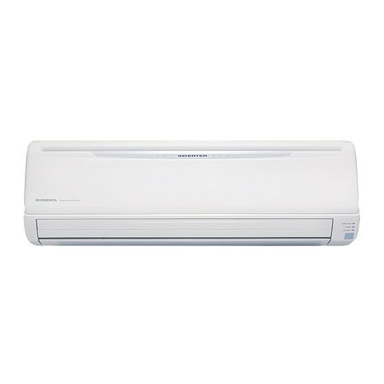
SPLIT TYPE
ROOM AIR CONDITIONER
WALL MOUNTED
Models
Indoor unit
ASHA24LCC AOHR24LCC
CONTENTS
SPECIFICATIONS . . . . . . . . . . . . . . . . . . . 1
DIMENSIONS . . . . . . . . . . . . . . . . . . . . . . . 2
REFRIGERANT SYSTEM DIAGRAM . . . . 3
CIRCUIT DIAGRAM . . . . . . . . . . . . . . . . . 4
INDOOR PCB CIRCUIT DIAGRAM . . . . .
ERROR CONTENTS . . . . . . . . . . . . . . . .
DISASSEMBLY ILLUSTRATION . . . . . . . 14
PARTS LIST . . . . . . . . . . . . . . . . . . . . . . . 20
STANDARD ACCESSORIES . . . . . . . . . .
type
Outdoor unit
5
8
13
22
Advertisement
Table of Contents

Summary of Contents for General ASHA24LCC
-
Page 1: Table Of Contents
Models Indoor unit Outdoor unit ASHA24LCC AOHR24LCC CONTENTS SPECIFICATIONS ....1 DIMENSIONS ..... . . 2 REFRIGERANT SYSTEM DIAGRAM . -
Page 2: Specifications
SPECIFICATIONS NOISE LEVEL ASHA24LCC C 47 dB / H 45 dB INDOOR UNIT HIGH AOHR24LCC C 41 dB / H 41 dB OUTDOOR UNIT INDOOR UNIT 7.10 kW C 36 dB / H 36 dB COOLING CAPACITY 8.10 kW C 32 dB / H 32 dB... - Page 3 OUTLINE AND DIMENSIONS Unit : mm INDOOR UNIT OUTDOOR UNIT 2006.02.28...
-
Page 4: Refrigerant System Diagram
REFRIGERANT SYSTEM DIAGRAM Heat exchanger ( INDOOR ) 3-Way valve 2-Way valve Muffler 4-Way valve Strainer Expansion valve Heat exchanger Strainer ( OUTDOOR ) Strainer Cooling Heating Refrigerant pipe diameter Liquid : 1/4" (6.35 mm) Gas : 5/8" (15.88 mm) 2006.06.21... -
Page 6: Indoor Pcb Circuit Diagram
INDOOR PCB CIRCUIT DIAGRAM CONTROL UNIT EZ-0051KHSE Model : ASHA24LCC TERMINAL BOARD THERMAL FUSE 102 OUTDOOR UNIT SERIAL EARTH TERMINAL EARTH BLACK WHITE GREEN 22007 22007 22007 CONTROLLER PCB ASSY INDICATOR PCB ASSY K05CX-0504HSE-C1 K05CY-0500HSE-D0 B05B-XASK CN6-1 REMOTE CONTROL UNIT... - Page 7 CONTROLLER PCB ASSY K05CX-0504HSE-C1 Model : ASHA24LCC H I C FOR SERIAL COMMUNICATIONS 280V MY064 1NH42 POWER SUPPLY CIRCUIT D12 D2F20U D9 D1FL20U R79, R81 - R84 D10 D1FL20U 10K <1/10W> x 5 I C 26 5D - 11 T1-12 R45 100K <RS - 2W>...
- Page 8 Model : ASHA24LCC INDICATOR PCB ASSY K05CY-0500HSE-D0 CN201 D201 SLR-325 D202 SLR-325 C201 D203 SLR-325 <F> I C201 R201 GP1UM261R <1/4W> + C202 2006.06.21...
-
Page 9: Outdoor Pcb Circuit Diagram
OUTDOOR PCB CIRCUIT DIAGRAM Model : AOHR24LCC INVERTER ASSY EZ-005EHUE UL1015 EMI FILTER AWG14 WHITE POWER SOURCE UL1015 UL1015 AWG14 AC220 - 240V AWG14 BLACK BLACK EMI FILTER 50 / 60Hz UL1015 F200 TM101 AWG20 UL1015 AWG14 ORANGE TLC 25A - 250V, B UL1015 AWG20 BLACK... - Page 10 CONTROLLER PCB ASSY Model : AOHR24LCC K05CU-0500HUE-C1 <1/10W> <1/10W> 2006.06.21...
- Page 11 Model : AOHR24LCC 2006.06.21...
- Page 12 TR PCB ASSY ( I P M ) K05CZ-0500HUE-TR0 Model : AOHR24LCC 2006.06.21...
- Page 13 Model : AOHR24LCC CAPACITOR PCB ASSY K05DG-0500HUE-P0 YELLOW SMOOTHING CIRCUIT WHITE YELLOW R200 C202 C200 C201 220K 660/ 660/ 660/ <2W> 450V 450V 450V BLUE VIOLET BLUE POWER_G 2006.06.21...
-
Page 14: Error Contents
ERROR CONTENTS Display Error Error Operation Timer LED 2 flash Serial signal (reverse) error, at operation start up 3 flash Serial signal (reverse) error, during oeration Serial signal error Normal 4 flash Serial signal (forward) error, at operation start up 5 flash Serial signal (forward) error, during operation 8 flash... -
Page 15: Disassembly Illustration
DISASSEMBLY ILLUSTRATION Model : ASHA24LCC 2006.06.21... - Page 18 Model : ASHA24LCC 2006.06.21...
- Page 19 Model : AOHR24LCC 2006.06.21...
- Page 20 Model : AOHR24LCC 2006.06.21...
-
Page 21: Parts List
PARTS LIST INDOOR UNIT Part No Ref No Descriprion Ord. Q'ty ASHA24LCC Front Panel Total Assy 9315335043 Intake Grille Assy 9315336033 Air Filter 9315014016 Clamper Grille 9306755010 Receiver Window 9315010018 Crossflow Fan Assy 9315024015 Bearing C Assy 9306628017 Casing Assy... - Page 22 OUTDOOR UNIT Parts No. Ord. Description Q'ty AOHR24LCC Top Panel Assy 9309230064 Cabinet Sub Assy 9314809019 Blow Grill 9308884015 Cabinet Right Assy 9309236028 Fan Ring 9308885012 Grip 9308880017 Switch Cover Assy 9309237032 4-Way Valve 9900163013 Pulse Motor Valve 9900056018 Condenser Assy B 9315303011 Condenser Assy 9315302014...
-
Page 23: Standard Accessories
STANDARD ACCESSORIES Name and Shape Part No. Wall hook bracket 9315023018 Remote control unit 9315027139 Remote control unit holder 9305642045 Battery (penlight) 0600185534 Cloth tape 9310519004 Tapping screw (big) 0700076046 Tapping screw (small) 0700019036 Air cleaning filter 9312153060 9311925071 Air cleaning filter frame 9368568009 Drain pipe... - Page 24 0606G3102...


Need help?
Do you have a question about the ASHA24LCC and is the answer not in the manual?
Questions and answers