Table of Contents
Advertisement
Available languages
Available languages
Quick Links
Advertisement
Chapters
Table of Contents

Related Manuals for HomeMatic HMW-IO-12-Sw7-DR


Summary of Contents for HomeMatic HMW-IO-12-Sw7-DR
- Page 1 Installations- und Bedienungsanleitung RS485 I/O-Modul 12 Eingänge 7 Schaltausgänge Hutschienenmontage HMW-IO-12-Sw7-DR Seite 4 - 20 Installation and Operating Manual RS485 I/O module 12 inputs 7 switch outputs for mounting on DIN rails HMW-IO-12-Sw7-DR Page 22 - 38...
- Page 2 1. Ausgabe Deutsch 12/2009 Dokumentation © 2007 eQ-3 AG, Deutschland Alle Rechte vorbehalten. Ohne schriftliche Zustim- mung des Herausgebers darf dieses Handbuch auch nicht auszugsweise in irgendeiner Form reproduziert 1. English edition 12/2009 werden oder unter Verwendung elektronischer, mecha- Documentation © 2007 eQ-3 AG, Germany nischer oder chemischer Verfahren vervielfältigt oder All rights reserved.
-
Page 3: Table Of Contents
Funktion ......7 Bewahren Sie die Anleitung zum späteren Nachschla- Allgemeine Systeminformation zu HomeMatic . . 8 gen auf! Allgemeine Hinweise zum Bussystem . -
Page 4: Funktion
• Galvanische Trennung von Eingängen und Aus- Unfall führen. gängen. • Umfangreiche Konfigurationsmöglichkeiten über Die Geräte sind nicht zum Freischalten geeignet. die HomeMatic Zentrale. Öffnen Sie das Gerät nicht, es enthält keine • Nichtflüchtiger Speicher für Konfigurationsdaten. durch den Anwender zu wartenden Teile. Das • Montage auf einer Stan d ard-Hutschiene inner- Öffnen des Gerätes birgt die Gefahr eines Stromschla- halb von Vertei lungen. -
Page 5: Allgemeine Systeminformation Zu Homematic
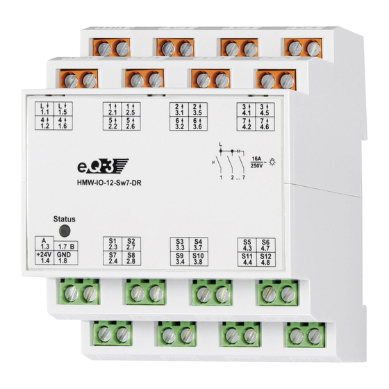
Gerätes über ein Programmiergerät und Software konfigurierbar. Welcher weitergehende Funktionsum- fang sich damit ergibt, und welche Zusatzfunktionen sich im HomeMatic System im Zusammenspiel mit weiteren Komponenten ergeben, entnehmen Sie bitte der gesonderten Konfigurationsanleitung oder dem HomeMatic Systemhandbuch. Alle technischen Dokumente und Updates finden Sie stets aktuell unter www.HomeMatic.com. Allgemeine Hinweise zum (A) - Außenleiteranschluss Lastseite (B) - Ausgangsklemmen Kanäle 1 –... -
Page 6: Topologie Des Bussystems
Gesamtstromaufnahme aller vorhandenen Module der Module einer Unterverteilung (max. 127 Stück) in der jeweiligen Unterverteilung dimensioniertes 24 jeweils miteinander zu verbinden. Ein Anschlusssche- V-Netzteil. Wenn eine zentrale Programmierung und ma mit Bus-System finden Sie im Systemhandbuch. Steuerung über die HomeMatic Zentrale erfolgen Beim Einsatz mehrerer Module ist ein Busabschluss soll, sollten die HMW-Busleitungen der einzelnen erforderlich. Informationen zum Anschluss finden Sie Unterverteilungen sowie die vom Steuer-PC bzw. -
Page 7: Installation
Anschlussbildern. Busabschnitte zu erreichen und ggf. eine Fehlersuche zu vereinfachen. Üblicherweise ist dies der Raum, in Vergewissern Sie sich, dass alle Anschlüsse dem die Zentrale des HomeMatic-Systems installiert fest und sicher in den Installationsklemmen wird. fixiert sind. Verdrahten Sie die Hutschienenmodule zur Busspan- nungsversorgung (Klemmen 1.4 und 1.8) mit dem... - Page 8 Klemme Funktion 1.1, 1.5 Außenleiteranschluss 2.1, 2.5 Geschaltete Phase Kanal 1 3.1, 3.5 Geschaltete Phase Kanal 2 4.1, 4.5 Geschaltete Phase Kanal 3 1.2, 1.6 Geschaltete Phase Kanal 4 2.2, 2.6 Geschaltete Phase Kanal 5 3.2, 3.6 Geschaltete Phase Kanal 6 4.2, 4.6 Geschaltete Phase Kanal 7 RS485-Bus (Bus A)
-
Page 9: Zuordnung Der Tastereingänge
Kanal-LED langsam blinkt (nach ca. 3 Sekunden). Das Modul befindet sich nun im Die 12 Tastereingänge des HMW-IO-12-Sw7-DR Anlernmodus. lassen sich ohne die HomeMatic Zentrale zu Aktor- • Betätigen Sie nun einen Taster an dem Tasterein- kanälen anderer(!) Aktoren, die Kanaltasten am Gerät gang (am selben oder einem beliebigen anderen besitzen zuordnen. -
Page 10: Aufheben Der Zuordnung Von Tastereingängen Zu Aktorkanälen
Je nach Aktor werden Tastereingänge unterschiedlich langsamen in das schnelle Blinken übergeht angelernt: (nach ca. 6 Sekunden). • Lassen Sie die Taste los. Das Schaltmodul befin- det sich nun im Löschmodus. Aktor Tastenverhalten • Drücken sie nun einen Taster am Tastereingang Schaltaktor, Angelernte Tasten verhalten sich eines Moduls, dessen Zuordnung Sie aufheben Dimmaktor wie Toggle-Taster wollen. -
Page 11: Technische Daten
Technische Daten Entsorgungshinweis: Gerät nicht im Hausmüll entsorgen! Elektro- Kommunikation: RS485-Bus nische Geräte sind entsprechend der Richt linie Gehäuseabmessungen: Standard-Hutschienengehäuse über Elektro- und Elektronik-Altgeräte über die mit 4 TE Breite 87 x 72 x 65 mm örtlichen Sammelstellen für Elektronik-Alt geräte zu (H x B x T) entsorgen. - Page 12 Function ......25 operation with your HomeMatic components. General system information on HomeMatic . . . 26 Keep the instructions handy for later consultation! General information on the bus system .
-
Page 13: Function
• Electrical isolation of inputs and outputs. electrical accidents. • Extensive configuration capabilities through the HomeMatic Centers. The devices are not intended to be isolated. • Non-volatile memory for configuration data. Do not open the device. It does not contain any • Installation on a standard DIN rail within divisi- parts to be maintained by the user. There is a ons. -
Page 14: General System Information On Homematic
Since normally a 230 V consumer is on the load side, on HomeMatic using VDE-conforming installation wires, such as e.g. This device is a component of the HomeMatic Home NYM wiring, etc. is required. The wire cross-section Control System. conform with the standard VDE regulations and is All devices are delivered in a standard configuration. -
Page 15: Topology Of The Bus System
Normally, this is the room in which the HomeMatic system Centre is installed. -
Page 16: Installation
Installation ty on the terminals. Observe the installation instructions for installa- Note that actual buttons (normally open) and tions in distribution systems. no rocker switches or push-button switches are used in the button input circuits. Connect each Position the DIN rail device on the DIN rail and lock it of the buttons between GND (terminal 1.8) and the in place. - Page 17 Terminal Function 1.1, 1.5 External conductor connection 2.1, 2.5 Switched channel 1 3.1, 3.5 Switched channel 2 4.1, 4.5 Switched channel 3 1.2, 1.6 Switched channel 4 2.2, 2.6 Switched channel 5 3.2, 3.6 Switched channel 6 4.2, 4.6 Switched channel 7 RS485-Bus (Bus A) RS485-Bus (Bus B) Power supply 24 V / DC...
-
Page 18: Allocation Of Button Inputs
• Press the programming button of the actuator Allocation of button inputs (channel) to be assigned on the module until the channel LED flashes slowly (after approx. 3 The 12 button inputs of the HMW-IO-12-Sw7-DR can seconds). The module is now in teach mode. be assigned to actuator channels of other(!) actuators • Now, actuate a button on the button input (on the... -
Page 19: Maintenance And Cleaning
Depending on the actuator, button inputs are taught from slow flashing to quickly flashing (after ap- differently: prox. 6 seconds). • Release the button. The module is now in delete mode. Actuator Button behavior • Now, press a button on the button input of a mo- Switch actuator, Taught buttons behave like dule for which you want to clear the assignment. Dimming actuator toggle switches The channel LED on the actuator goes dark and Depending on whether teach the assignment is deleted, the actuator (channel) -
Page 20: Technical Specifications
9 Technical specifications Instructions for disposal: Do not dispose off the device as part of Communication: RS485-Bus household garbage! Electronic devices are to be Housing dimensions: Standard DIN rail housing with disposed of in accordance with the guidelines 4 units width 87 x 72 x 65 mm concerning electrical and electronic devices via the local (H x W x D) collecting point for old electronic devices. - Page 21 Bevollmächtigter des Herstellers: Manufacturer’s authorised representative: eQ-3 AG Maiburger Straße 29 26789 Leer / GERMANY www.eQ-3.de...
Need help?
Do you have a question about the HMW-IO-12-Sw7-DR and is the answer not in the manual?
Questions and answers