Table of Contents
Advertisement
Quick Links
EVK-L4
TOBY-L4 series
Cellular Evaluation Kits
User Guide
Abstract
This guide explains how to set up the EVK-L4 Evaluation Kits to
begin evaluating the u-blox TOBY-L4 series cellular modules
supporting LTE-FDD, LTE-TDD, DC-HSPA+, (E)GPRS multi-mode and
multi-band radio access technologies. The modules offer up to
301.5 Mb/s download and up to 51.0 Mb/s upload data rates with
Category 6 LTE-Advanced carrier aggregation technology.
www.u-blox.com
UBX-17013792 - R01
Advertisement
Table of Contents

Related Manuals for Ublox EVK-L4


Summary of Contents for Ublox EVK-L4
- Page 1 Cellular Evaluation Kits User Guide Abstract This guide explains how to set up the EVK-L4 Evaluation Kits to begin evaluating the u-blox TOBY-L4 series cellular modules supporting LTE-FDD, LTE-TDD, DC-HSPA+, (E)GPRS multi-mode and multi-band radio access technologies. The modules offer up to 301.5 Mb/s download and up to 51.0 Mb/s upload data rates with...
- Page 2 EVK-L4 - User Guide Document Information Title EVK-L4 TOBY-L4 series Subtitle Cellular Evaluation Kits Document type User Guide Document number UBX-17013792 Revision and date 21-Nov-2017 Disclosure restriction This document applies to the following products: Name Type number Modem version Application version...
-
Page 3: Table Of Contents
1.12 Switching off the EVK-L4 ........................ 16 Appendix .......................... 17 A Setting up AT terminal applications for communication with the EVK-L4 ..... 17 Setting up cellular packet data connection on PC ............ 18 Examples of AT commands ..................20 Define a default bearer for connectivity ....................20 D Current consumption measurement ................. -
Page 4: Starting Up
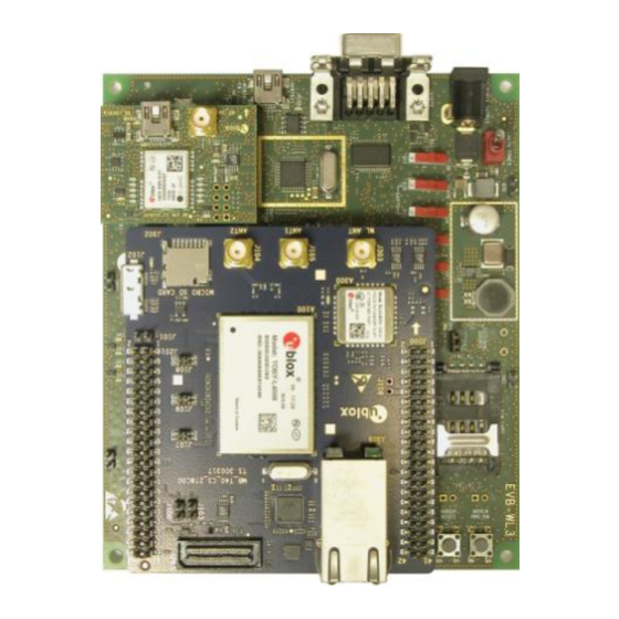
1 Starting up 1.1 EVK-L4 overview The EVK-L4 kits are powerful and easy-to-use tools that simplify the evaluation of u-blox TOBY-L4 series multimode LTE Cat 6 Advanced / 3G / 2G cellular modules. The TOBY-L4 series include the following LTE Cat 6 modules with 3G and 2G fallback: ... - Page 5 J201 Cellular power-on SW302 Cellular adapter board RJ45 Ethernet Connector Headset jack Cellular reset TOBY-L4 Cellular module J305 J303 SW303 Figure 1: Overview of the EVK-L4 evaluation kit for TOBY-L4 modules UBX-17013792 - R01 Starting up Page 5 of 23...
-
Page 6: Evk-L4 Block Diagram
EVK-L4 - User Guide 1.2 EVK-L4 block diagram Figure 2 shows the main interfaces and internal connections of the EVK-L4 evaluation kit: Native MicroSD VCC jumper RJ45 3.8 V (J302) 12 V Main power switch card holder (J305) (J102) Step - Down... -
Page 7: Switches, Jumpers And Buttons
DIL B2B connector on the ADP board GNSS V_BCKP Slide switch to connect / disconnect backup battery to V_BCKP pin of the GNSS module SW204 Table 1: Description of EVK-L4 switches and buttons UBX-17013792 - R01 Starting up Page 7 of 23... -
Page 8: Leds
Pulses at 1 Hz when valid GNSS fix DS121 ADP-GNSS Cellular / GNSS DDC Cellular / GNSS module communication over DDC (I C) interface DS132 ADP-GNSS Table 2: Description of EVK-L4 LEDs UBX-17013792 - R01 Starting up Page 8 of 23... -
Page 9: Connectors
Ground terminals for the probe reference J402, J403 J405, J406 Table 3: Description of EVK-L4 connectors CAUTION! IN THE UNLIKELY EVENT OF A FAILURE IN THE INTERNAL PROTECTION CIRCUITRY, THERE IS A RISK OF AN EXPLOSION WHEN CHARGING A FULLY OR PARTIALLY DISCHARGED BATTERY. -
Page 10: Evk-L4 Pin Out
EVK-L4 - User Guide 1.6 EVK-L4 pin out 1.6.1 Routing of TOBY-L4 modules’ pins up to connectors available on the ADP-L4 TOBY-L4 Connector TOBY-L4 Connector TOBY-L4 Connector Pin N° Name Name / Pin N° Pin N° Name Name / Pin N°... - Page 11 Table 4: Interfaces of TOBY-L4 series modules, as routed up to the 42-pin Dual-In-Line Board-to-Board connectors (J200, J201) and up to other connectors available on the adapter board ADP-L4 of the EVK-L4 evaluation kit The pins / interfaces that are not supported by a specific TOBY-L4 module product version should not be driven by an external device (see the TOBY-L4 series Data Sheet [2] and the TOBY-L4 series System Integration Manual [3] for the features supported by each TOBY-L4 module product version).
-
Page 12: Pin-Out Of The 42-Pin Dual-In-Line Board-To-Board Connectors On The Adp-L4
EVK-L4 - User Guide 1.6.2 Pin-out of the 42-pin Dual-In-Line Board-to-Board connectors on the ADP-L4 DIL B2B J201 DIL B2B J200 Signal Name Pin N° Pin N° Signal Name Signal Name Pin N° Pin N° Signal Name HOST_SELECT0 VSIM1 Not connected... -
Page 13: Routing Of The Toby-L4 Modules' Uart1, Uart2 And/Or Uart3 Interface
Integration Manual [3] for the features supported by each TOBY-L4 module product version). 1.7 Software installation The USB drivers are available with the EVK-L4. Executable files can be downloaded from www.u-blox.com/evk- downloads and saved to any location on the computer hard drive. The installation can be started by running the executable file on a computer with the Windows operating system. -
Page 14: Board Setup
EVK-L4 - User Guide 1.8 Board setup 1. Insert a SIM card into the SIM card holder (J300 on the EVB). 2. Connect a cellular antenna provided with the evaluation kit box to the Primary cellular antenna SMA connector on the ADP-L4 (ANT1, RF input/output for transmission and reception of LTE/3G/2G RF signals) 3. -
Page 15: Enabling Error Result Codes
EVK-L4 - User Guide See Appendix A for how to configure the u-blox m-center AT terminal for Windows. 11. For communication via the cellular module’s UART interfaces, the following connections are allowed and can be alternatively enabled in a mutually exclusive way (see Table 8 for the switch position and LED status): a. -
Page 16: Registration On A Cellular Network
1.12 Switching off the EVK-L4 To switch off the EVK-L4, send the +CPWROFF AT command. Make sure to use this command before switching off the main power, otherwise settings and configuration parameters may not be saved in the internal non- volatile memory of the cellular module. -
Page 17: Appendix
3. On the Home page, set up the AT COM port; for the setting values, see section 1.8. Check with the Windows Device Manager to find out which COM port is being used by the EVK-L4. 4. Enable the connection to the u-blox cellular module by clicking on the Connect button. -
Page 18: B Setting Up Cellular Packet Data Connection On Pc
This section describes how to set up a packet data connection with the Windows 7 operating systems (for PCs) and EVK-L4, using the TCP/IP stack of the PC (external TCP/IP stack). The following example describes how to configure the Windows PC to use the module as a high data rate mobile router, over the native USB interface of the cellular module connected by the Cellular Native USB connector on the ADP. - Page 19 EVK-L4 - User Guide 3. Search for "Internet Protocol Version 4 (TCP/IPv4)" and click on "Properties". Figure 8: Local area connection properties 4. Check the option "Obtain an IP address automatically". 5. Then check the "Obtain DNS server address automatically" option.
-
Page 20: C Examples Of At Commands
EVK-L4 - User Guide C Examples of AT commands For the complete description and syntax of the AT commands supported by TOBY-L4 series modules, see the u-blox AT commands Manual [1]. C.1 Define a default bearer for connectivity To change the PDN settings for a default EPS bearer, edit the <cid>=1 PDN by means of the AT+CGDCONT AT command. -
Page 21: D Current Consumption Measurement
EVK-L4 - User Guide D Current consumption measurement The current consumption of TOBY-L4 series modules can be measured on the EVK-L4 by removing the jumper socket from the Cellular VCC supply jumper (J404 on the EVB), described in Figure 10. -
Page 22: Declaration Of Conformities
(petrol stations, refineries…). Any changes or modification made to this equipment will void its compliance to the safety requirements. Maintenance, inspections and/or repairs of the EVK-L4 shall be performed by u-blox AG. Related documents [1] u-blox AT commands Manual, Docu No UBX-13002752... -
Page 23: Contact
EVK-L4 - User Guide Contact For complete contact information, visit us at www.u-blox.com u-blox Offices North, Central and South America Headquarters Asia, Australia, Pacific Europe, Middle East, Africa u-blox America, Inc. u-blox Singapore Pte. Ltd. u-blox AG Phone: +1 703 483 3180... - Page 24 Mouser Electronics Authorized Distributor Click to View Pricing, Inventory, Delivery & Lifecycle Information: u-blox ADP-L4006 ADP-L4106 ADP-L4906 EVK-L4006 EVK-L4106 EVK-L4206 EVK-L4906...
Need help?
Do you have a question about the EVK-L4 and is the answer not in the manual?
Questions and answers