Advertisement
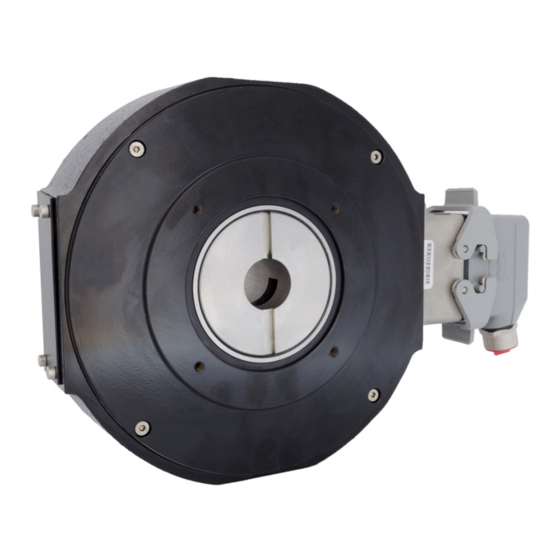
NorthStar
™
brand
NexGen RIM Tach HT85 Encoder
Key Features
• Hollowshaft Design Mounts Easily to Large Motor
Shafts, up to 4.50" in Diameter
• New Sensor Provides up to 0.075" of Air Gap,
Over 50% More Than Competitive Models
• Expanded Resolution up to 2400PPR
• Redesigned Circuitry for On-Board Diagnostics with
LED and Alarm Output
• Multiple Bore Sizes Available, Including Tapered Shafts
• Stainless Steel and Ductile Cast Iron Construction
SPECIFICATIONS
STANDARD OPERATING CHARACTERISTICS
Code: Incremental, Magnetic
Pulses per Revolution: 60-2400 PPR
Phasing Sense: A leads B for Counter-Clockwise
rotation (CCW) viewing encoder-mounted end
Quadrature Phasing: 90° ± 45°
Symmetry: 50% ±15%
Number of Output Modules: Single or Dual
ELECTRICAL
Input Power Requirements: 5-26VDC, 95mA
typical per sensor module, plus line driver load
Output Signals: IC-WE Differential Line Driver:
150mA, sink or source
Frequency Response: 0 - 180kHz Data & Index
Noise Immunity: Tested to EN61326-1
Electrical Immunity: Reverse polarity and short
circuit protected
ELECTRICAL CONNECTIONS
Signal
Connector Pin
Common
B
A
Z*
Alarm †
Vcc (5-26 VDC)
_
B
_
A
_
Z*
Shield
* Index (Z) optional. See Ordering Information
† Alarm not available with Pigtail cable. See Ordering Information
Encoder Installation Manual
ELECTRICAL (Cont.)
Connector: 10 pin industrial duty latching, sealed
NEMA 4 &12, IP65. Optional MS3102 10 pin,
Pigtail Cable, or Latching connector on cable
extension
MECHANICAL
Bore Diameter: 1" to 4-1/2", straight or tapered
Mounting Configuration: Hollow Shaft mount
with Anti-Rotation Tether
Shaft Speed: 3,600 RPM
Shaft Length Required: 2.5" min
Acceleration Rate: 3,600 rpm/sec max
Allowable Shaft End-Play: 0.25" (Subject to
RPM Limitation)
Allowable Shaft Runout: 0.010" TIR (Subject to
RPM Limitation)
Housing Material: Cast Iron/Stainless Steel
Weight: 30 lbs
Pigtail Cable
1
Black
2
Green
3
Blue
4
Violet
5
N/A
6
Red
7
Yellow
8
Gray
9
Orange
10
Braid
MS 3102E18-IT#
A
E
D
C
F
B
H
G
I
J
ENVIRONMENTAL
Operating Temperature Range: -40°C to +85°C
Storage Temperature Range: -40°C to +120°C
Shock (Sensor Module): 30 G's Min
Vibration: 18 G's @ 5-2000 Hz spectrum
Humidity: Up to 98% (non-condensing)
CONTENTS
Specifications ........................Pg 1
Important ................................Pg 2
Mechanical Installation .........Pg 4
Sensor Module Installation ...Pg 5
Electrical Installation .............Pg 6
Dimensions ............................Pg 7
Ordering Information .............Pg 7
EN 61326-1
Page 1
Advertisement
Table of Contents

Related Manuals for DYNAPAR NorthStar NexGen RIM Tach HT85


Summary of Contents for DYNAPAR NorthStar NexGen RIM Tach HT85
-
Page 1: Table Of Contents
NorthStar ™ Encoder Installation Manual brand NexGen RIM Tach HT85 Encoder Key Features • Hollowshaft Design Mounts Easily to Large Motor Shafts, up to 4.50” in Diameter • New Sensor Provides up to 0.075” of Air Gap, Over 50% More Than Competitive Models •... -
Page 2: Important
Cable - The use of shielded cable is recommended coder and should be free of induced transients. Com- for all encoder installations. When a Dynapar brand mon (also referred to as Com, supply common, and encoder is ordered, the type of termination is gener-... - Page 3 IMPORTANT INSTALLATION INFORMATION FEATURES (cont.) LED STATUS LIGHT: When encoders have a differential line driver, there A multicolor LED Status light will indicate to the user are two signals for each of the outputs. Each signal the overall condition of the encoder. The LED is built (A, B and Z) has a compliment or inverse (A, B and Z into the encoder and does not require any additional referred to as A not, B not, and Z not).
-
Page 4: Mechanical Installation
INSTALLATION 1.0 MECHANICAL INSTALLATION 4. Tighten the clamping ring segment as follows (see The RIM Tach® HT85 is shipped partially assembled. Figure 2): There are no field gap checks, axial alignment, or 1) Look inside the access plate hole and rotate run out checks required. -
Page 5: Sensor Module Installation
1.1 SENSOR MODULE INSTALLATION To install the Sensor Module, perform the following steps. See Figure 4. 1. Remove sensor module and mating connector from packaging. 2. Separate mating connector from sensor module by releasing the two latches. Figure 3: Anti-Rotation Arm Orientation 3. -
Page 6: Electrical Installation
1.2 ELECTRICAL INSTALLATION 4. Mate connector into place on sensor mount and IT IS VERY IMPORTANT that the mating connector snap the two latches into place. If only one sensor is and the encoder body be isolated from electrical being installed, ensure cover plate is installed over ground in the wiring and conduit to prevent motor or other sensor hole. -
Page 7: Dimensions
Fax: +1.847.662.4150 Fax: +1.847.662.4150 Uhlandstrasse 49, 78554 Aldingen WWW.DYNAPAR.COM custserv@dynapar.com northstar.techsupport@dynapar.com www.hengstler.com Headquarters: 1675 Delany Road • Gurnee, IL 60031-1282 • USA NorthStar™ brand is a trademark of DYNAPAR. All rights reserved. Document No. 703284-0001, Rev. A ©2020 DYNAPAR Page 7...
Need help?
Do you have a question about the NorthStar NexGen RIM Tach HT85 and is the answer not in the manual?
Questions and answers