Table of Contents
Advertisement
Quick Links
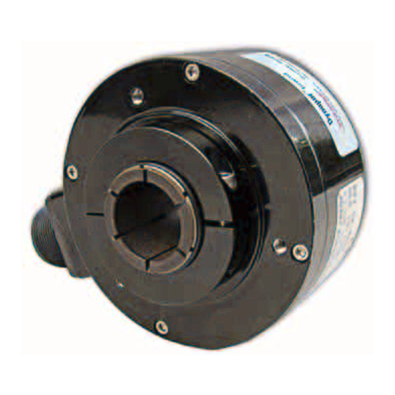
Dynapar
SERIES HS35R
Heavy Duty Hollowshaft Encoder
Document No.: 702761-0001
Revision Level: S
Sept. 16, 2013
DESCRIPTION
The Series HS35R Sealed Hollowshaft encoder is equipped with an
unbreakable disk that handles the most severe shock and vibration. Its
hollow shaft mount and anti-rotation tether reduce bearing wear and
maintenance. Series HS35R has electrical protection from overvolt-
age, reverse voltage, and output short circuits when ordered with
standard operating temperature configuration.
Series HS35R is not only electrically & thermally isolated (for shaft
sizes 1.125" and under) but also environmentally sealed with shaft
seals at both ends.
APPLICATION ENVIRONMENT
KEY FEATURES
The encoders can be provided with optional hazardous location
• Phased Array Sensor for Reliable Signal
certification that allows use in environments stated in:
Output
Class I, Division 2, Group A: atmospheres such as
acetylene;
Class I, Division 2, Group B: atmospheres such as
hydrogen;
• Rugged Design Withstands up to 400g
Class I, Division 2, Group C: atmospheres such as
Shock and 20g Vibration
ethyl ether and ethylene;
Class I , Division 2, Group D: atmospheres such as
acetone, ammonia, benzene, butane, cyclopropane,
• Unbreakable Code Disc up to 5000PPR
ethanol, gasoline, hexane, methanol, methane, natural
gas, naphtha, and propane.
Class II, Division 2, Group F & G.
• Heavy Duty Design Rated for IP67
Classifications of hazardous locations are subject to the approval of
the authority having jurisdiction. Refer to Article 500 of the National
Electrical Code (NEC) or Section 18 of the Canadian Electrical Code
(CEC).
• Customizable Mounting Options including
Note: For CSA Division 2, Group F & G certification, Dynapar
Torque Arm with Optional Grounding
Adapter Kit P/N 114064-0001 must be used.
Strap
Encoder Installation Manual
™
brand
Application Assistance 1.800.234.8731 (847.662.6633)
IMPORTANT INSTALLATION INFORMATION
Mounting the Encoder: Before Installation, ensure power is discon-
nected from encoder and motor or machine.
CAUTION: The loads applied to the encoder shaft must be in
accordance with the specificatios of this device.
Important Wiring Instructions: Use of shielded cable is recom-
mended for all encoder installations. The shield should be connected
to signal-ground at the receiving device only.
Grounding: For applications with high ground potential differ-
ences, DO NOT ground the encoder through both machine and
controls end. Connect the shield at the controls end only. NOTE:
If the shield is connected at both ends, grounding problems that
degrade system performance can result.
CE Grounding Measures – For best EMC immunity the cable
screen must be grounded on both encoder and controls end. For
cable lengths longer than 30m or outdoor applications, additional
measures must be implemented to comply with CE require-
ments. Connection of the encoder to DC power supply network is
prohibited if CE compliance is required. CE-compliant products
are tested to EN61326-1 EMC.
In all cases, system CE compliance is ultimately the responsibil-
ity of the manufacturer integrating the encoder.
Connecting the shield at both ends can cause grounding
problems that degrade system performance.
If possible, run the encoder cable through a dedicated conduit (not
shared with other wiring). Use of conduit will protect the cable from
physical damage and provide a degree of electrical isolation. Do not
run the cable in close proximity to other conductors that carry current
to heavy loads such as motors, motor starters, contactors, solenoids,
etc. This practice can induce electrical transients in the encoder
cable, potentially interfering with reliable data transmission.
Refer to Electrical Connections table for wiring information.
To avoid possible damage, do not connect or disconnect the encoder
connector or wiring while power is applied to the system.
CAUTION: Unused encoder signal wires must be individually
insulated and under no circumstances be in contact with
ground, voltage sources, or other signal lines.
Page 1
Advertisement
Table of Contents

Related Manuals for DYNAPAR SERIES HS35R


Summary of Contents for DYNAPAR SERIES HS35R
-
Page 1: Key Features
Important Wiring Instructions: Use of shielded cable is recom- mended for all encoder installations. The shield should be connected Series HS35R is not only electrically & thermally isolated (for shaft sizes 1.125” and under) but also environmentally sealed with shaft to signal-ground at the receiving device only. -
Page 2: Mechanical Installation
The following instructions are meant to assist in proper installation of FLAT END CAP Dynapar brand, Series HS35R hollowshaft encoders. The encoder is a speed and position transducer that when mounted to a rotating shaft, produces output pulses that are directly proportional to the shaft speed and direction. - Page 3 Page 3 STEP 6: SLIDE ENCODER ON SHAFT STEP 9: GOOD INSTALLATION CHECK POINT Carefully slide the encoder all the way down until the tether rests on the motor face without any stress on the tether. Do not tighten the shaft clamp on the encoder yet MAXIMUM 2.60...
-
Page 4: Specifications
Page 4 SPECIFICATIONS MECHANICAL STANDARD OPERATING CHARACTERISTICS Shaft Material: 6061-T6 Aluminum Code: Incremental Bore Diameter: 6mm to 28mm, 1/4‰ to 1.25‰, electrically Resolution: to 5000 PPR (pulses/revolution) See Ordering isolated Information Mating Shaft Length: 1.25‰, Minimum, 1.60‰, Recommended Shaft Speed: 6000 RPM, Maximum (Enclosure Rating is IP64 at speed over 5000 RPM) Starting torque: 8.0 in-oz. - Page 5 Page 5 inch DIMENSIONS [mm] 10-32 CLAMP SCREW TORQUE TO 50 - 55 IN/LBS 1.250 I.D. COMPLETELY THRU THE SHAFT WITH LOCTITE ON THREADS [22.61] FOR DIA. 1.250 +.000, -.003" SHAFT [ 17.07 ] [19.05 ] 21.84 10-32 UNC-2B (X) .19 DEEP ON DIA.
- Page 6 Page 6 inch DIMENSIONS (24X) 15˚ [mm] 24X Ø .200 [5.08] 4.50 ON A Ø3.000 [76.2] B.C.D [114.3] 2.50 Ø2.506 [63.5] [63.65] Ø3.50 [89] .500 [12.7] Ø.20 15˚ (24X) [.51] (24X) ON 3.000 [76.2] B.C.D 1.25 [31.75] .63 [16] (2X) 45˚ X .125 [3.17] 1.25 [31.75] 2.30...
- Page 7 Page 7 SPECIFICATIONS LED OUTPUT OPTION Note: The following LED option specifications may supercede Dynapar Exclusive: The LED Output Indicator Option makes Dynapar standard encoder specifications brand the only encoders that show they are installed and operating correctly. LED Characteristics: On when output signal is < 2 VDC Input Green light emitting diodes (LEDs) are connected to the signal outputs Power: 5 to 26 VDC at 0.5mA per channel;...
-
Page 8: Ordering Information
Q Same as “D” with Extended temp range R Same as “E” with Extended temp range W ABZ, 10-24VDC Line Driver for cable runs up to 500 ft/120m using the Dynapar cable assemblies listed below 10 foot Cable Assemblies with MS Connector...
Need help?
Do you have a question about the SERIES HS35R and is the answer not in the manual?
Questions and answers