Table of Contents
Advertisement
Quick Links
Advertisement
Table of Contents

Related Manuals for Keysight N7010A


Summary of Contents for Keysight N7010A
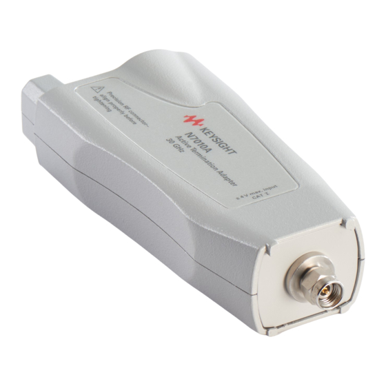
- Page 1 Keysight N7010A Active Termination Adapter User’s Guide...
- Page 2 FAR 2.101, pursuant a foreign language) without prior agreement to FAR 12.211 and 27.404.2 and DFARS and written consent from Keysight Technolo- Restricted Rights Legend 227.7102, the U.S. government acquires gies, Inc. as governed by United States and no greater than Limited Rights as U.S.
-
Page 3: Table Of Contents
Contents General Information / 5 Connecting the N7010A / 6 Using the N7010A / 8 N7010A’s Low Noise Floor / 11 Avoiding Costly Repairs / 12 Safety Information / 14 Inspecting the N7010A / 17 Cleaning the N7010A / 17... - Page 4 Contents N7010A User’s Guide...
-
Page 5: General Information
The N7010A active termination adapter is a 30 GHz single-ended adapter featuring a user adjustable common termination voltage (V ) and extremely low term noise performance. The N7010A is ideal for high SNR (low noise) measurements for standards such as: • HDMI 2.0, • DisplayPort, and •... -
Page 6: Connecting The N7010A
Click on the “Drivers, Firmware & Software” tab. N7010A Input Connection The N7010A comes with a 2.9 mm precision connector and a removable 3.5 mm connector saver as shown in Figure 1 on page 7. - Page 7 Torque all cables and adapter connections to the 2.9 mm connector to 8 in-lbs CAUTION (90 N-cm). Torque all cables and adapter connections to the 3.5 mm connector saver to 8 in-lbs CAUTION (90 N-cm). Figure 1 N7010A with Supplied Connector Saver N7010A User’s Guide...
-
Page 8: Using The N7010A
Figure 2 Simplified Function Diagram To avoid damaging the N7010A, the maximum low frequency (LF) input voltage must not CAUTION exceed ±8V. LF is defined as DC to approximately 50 kHz, and AC is defined as greater than approximately 50 kHz. - Page 9 Probe Dialog Box Control The V control allows the N7010A to subtract the DC voltage component from V thereby allowing the N7010A output to be centered around ground. To set the V control, perform the following steps on the oscilloscope: Click Setup >...
- Page 10 , which means the term signal into the oscilloscope is centered around ground. is the voltage at the input of the N7010A. If the source driving the N7010A has a non-zero N OTE output impedance then V will interact with V...
-
Page 11: N7010A's Low Noise Floor
General Information N7010A’s Low Noise Floor With the N7010A’s low attenuation ratio setting (1.16:1), the adapter has an extremely lower noise floor. The following two pictures compare two eye diagrams for the same MIPI M-PHY Gear 3 data rate signal at 5.8304 Gb/s. The amplitude... -
Page 12: Avoiding Costly Repairs
General Information Avoiding Costly Repairs When connecting or using the N7010A, use caution to avoid damaging the oscilloscope’s channel input circuits due to electrostatic discharge (ESD). When the N7010A is connected to the oscilloscope, the CAUTION oscilloscope’s channel input circuits can be damaged by electrostatic discharge (ESD). - Page 13 General Information Figure 6 ESD Workstation N7010A User’s Guide...
-
Page 14: Safety Information
Safety Information This manual provides information and warnings essential for operating the N7010A in a safe manner and for maintaining it in safe operating condition. Before using this equipment and to ensure safe operation and to obtain maximum performance from the probe, carefully read and observe the following warnings, cautions, and notes. - Page 15 You must not negate the protective action by using an extension cord (power cable) without a protective conductor (grounding). Grounding one conductor of a two-conductor outlet is not sufficient protection. N7010A User’s Guide...
- Page 16 Do not use repaired fuses or short-circuited fuse holders. To do so could cause a shock or fire hazard. Capacitors inside the instrument may retain a charge even if the instrument is WARNING disconnected from its source of supply. N7010A User’s Guide...
-
Page 17: Inspecting The N7010A
Cleaning the N7010A Disconnect the N7010A from the oscilloscope and clean the N7010A with a soft cloth dampened with a mild soap and water solution. Make sure that the N7010A is completely dry before reconnecting it to an oscilloscope. Avoid using abrasive cleaners and chemicals containing benzene or similar solvents. -
Page 18: Returning The Product For Service
General Information Returning the Product for Service If the N7010A is found to be defective we recommend sending it to an authorized service center for all repair and calibration needs. Perform the following steps before shipping the probe back to Keysight Technologies for service. -
Page 19: Contacting Keysight Technologies
General Information Contacting Keysight Technologies For technical assistance, contact your local Keysight Call Center. • In the Americas, call 1 (800) 829-4444 • In other regions, visit http://www.keysight.com/find/assist • Before returning an instrument for service, you must first call the Call Center at 1 (800) 829-4444. - Page 20 General Information N7010A User’s Guide...
-
Page 21: Specifications And Characteristics
Characteristics Specifications and Characteristics N7010A Dimensions The tables in this chapter list the specifications and characteristics for the N7010A adapter. Bandwidth and input resistance at DC are warranted specifications for the N7010A. Connect the N7010A to a powered-on oscilloscope for at least 20 minutes before any testing to allow the adapter to warm up. -
Page 22: Specifications And Characteristics
Bandwidth (–3 dB) > 30 GHz (warranted), >32 GHz (typical) Rise time (10% — 90%) 14.5 ps Attenuation ratio 1.16:1 Noise with oscilloscope Refer to “N7010A’s Low Noise Floor" on page 11. range –4V to +4V term accuracy ±2 mV term range –4V to +4V... - Page 23 Category: With reference to the equipment types in the WEEE Directive Annex I, this product is classed as a “Monitoring and Control instrumentation” product. Do not dispose in domestic household. To return unwanted products, contact your local Keysight office, or refer to www.keysight.com for more information. N7010A User’s Guide...
- Page 24 Specifications and Characteristics Figure 8 Typical N7010A Bandwidth N7010A User’s Guide...
- Page 25 Specifications and Characteristics Figure 9 N7010A Typical Input Return Loss N7010A User’s Guide...
-
Page 26: N7010A Dimensions
Specifications and Characteristics N7010A Dimensions Figure 10 N7010A Dimensions with Connector Saver N7010A User’s Guide... -
Page 27: Performance Verification
Ensure that the input voltage to the oscilloscope never exceeds ±4V. CAUTION Allow the N7010A termination adapter to warm up for at least 20 minutes. NOTE Let the oscilloscope warm up before testing. The oscilloscope under test must be warmed up... -
Page 28: Test 1. Bandwidth
Performance Verification Test 1. Bandwidth Bandwidth for the N7010A Active Termination Adapter is specified when used with a Keysight Infiniium Oscilloscope that has a 32 GHz bandwidth. The procedure in this section is very similar to the procedure described in the service manual for any of the 32 GHz Infiniium oscilloscopes except that the bandwidth need only be tested at the oscilloscope’s 50 mV/div setting. - Page 29 Remove any connector saver that is installed on the oscilloscope’s Channel 1. b Connect the N7010A to Channel 1. The N7010A should have its supplied 3.5 mm connector saver installed. Figure 11 Bandwidth Test Setup N7010A User’s Guide...
- Page 30 Performance Verification c Use an 11901A adapter to connect the N7010A to one of the 11667C power splitter’s outputs. d Use an 11901C adapter to connect the power sensor to the power splitter’s remaining output. e Connect the microwave cable to the power splitter’s input.
- Page 31 4.0 μW, then V = (4.0 x 10 X 50Ω) = 14.1 mV 50Ω × meas Record the V value here and in Table 7 on page 37 as V at 50 MHz. at 50 MHz: ______________ N7010A User’s Guide...
- Page 32 The power meter reads the input power to the scope channel. Convert this measurement to V using the following expression. For example, if the power meter reading is 4.0 μW, then V = (4.0 x 10 x 50Ω) = 14.1 mV 50Ω × meas N7010A User’s Guide...
- Page 33 30 GHz 1.0023 Record this value here and in Table 7 on page 37 as the Calculated Gain at 30 GHz. To pass this test, this value must be greater than -3.0 dB. Gain at 30 GHz: ______________ N7010A User’s Guide...
-
Page 34: Test 2. Input Resistance At Dc
In the Probe Configuration menu for Channel 1, select Options for the N7010A block and make sure that the Termination Voltage is set to zero. Connect the BNC cable to the N7010A using the SMA (m) to BNC (f) adapter as shown in Figure 15 on page 35. - Page 35 Reverse the banana plug connection to the DVM. Record the measured input resistance: Input resistance (R ): ______________ Calculate the average input resistance using the following expression, and record this value here and in Table 8 on page 37. Average Input Resistance: ______________ Average Input Resistance ------------------ - N7010A User’s Guide...
- Page 36 Performance Verification The average input resistance must meet the 50 ohm ±3% specification: 48.5Ω Average Input Resistance 51.5Ω ≤ ≤ N7010A User’s Guide...
-
Page 37: Performance Test Record
(Read on Oscilloscope) Calculated Gain (Test Limit –3 dB) 50 MHz 30 GHz Table 8 Results for Test 2. Input Resistance at DC Test Test Limits Result Ω ≤ ≤ Ω Average Input Resistance 48.5 measured 51.5 N7010A User’s Guide... - Page 38 Performance Verification N7010A User’s Guide...
-
Page 39: Index
(ESD), graph of typical input return loss, environmental specifications, inspecting, using, ESD Workstation, noise contribution, service, WEEE Directive, firmware version, oscilloscope, function diagram, operation, oscilloscope compatibility, firmware version, humidity, N7010A User’s Guide... - Page 40 Index N7010A User’s Guide...
Need help?
Do you have a question about the N7010A and is the answer not in the manual?
Questions and answers