Table of Contents
Advertisement
Advertisement
Table of Contents

Related Manuals for VisionTek VT4900


Summary of Contents for VisionTek VT4900
- Page 1 VT4900 USB-C KVM Docking Station User Manual V1.2...
-
Page 2: Table Of Contents
Table of Contents Quick Installation / Setup ......................4 Key Features ........................4 Box Contents ........................4 I/O Description ........................4 Hardware Installation ......................5 Host (Display) Switch Mode ..................... 6 Specifications ........................6 Driver Installation ........................7 DisplayLink Driver – Windows ..................7 DisplayLink Driver –... - Page 3 ABOUT THIS MANUAL This manual is designed for use with the VT4900 Docking Station. Information in this document has been carefully checked for accuracy; however, no guarantee is given to the correctness of the contents. The information in this document is subject to change without notice. The manufacturer...
- Page 4 With the KVM Sharing features, the VT4900 allows a user to switch their display (HDMI / DP / DP) monitors / USB – Peripherals by using multi-switch mode, with Dual Host (Desktop / Laptop / Tablet) at the same time.
-
Page 5: Quick Installation / Setup
Supports Dual Power Delivery – PD 3.0, up to 100W Per System 1.2 Box Contents 1 x VT4900 USB-C KVM Docking Station 2 x USB-C to C Full Pin Cables 1 x Power Adapter -230W (20V/11.5A) ... -
Page 6: Hardware Installation
Connect the Power adapter (PSU) to the DC power jack on the VT4900 Docking Station. Connect the included 2 x USB-C to C cables to USB-C (Upstream) Ports (Host A / B) on the Docking Station and then to an available USB-C Port on each Host computer. -
Page 7: Host (Display) Switch Mode
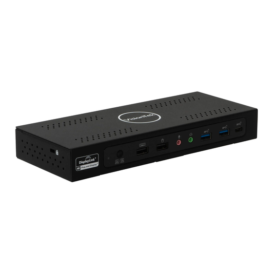
----------------------------------------------------------------------------------------------------------------------------------- = Display from Host 1 / = Display from Host 2 1.6 Specifications Model Number VT4900 USB 3.2 Gen 2 USB Type-C Cable (1M/5A) x2 Upstream: USB Type-C × 2 (3.2 Gen 2 x1) Interfaces USB 3.2 Gen 2 Type-A ×2 / USB 2.0 Type-A x2 Downstream: USB 3.2 Gen 2 Type-C x1 | Audio x2 (In and Out) -
Page 8: Driver Installation
2 Driver Installation Download the latest drivers (Installation Tool) for Windows, Mac OS and Android OS from the following link: http://www.displaylink.com/downloads/ DisplayLink Driver – Windows Download the latest official drivers from the “DisplayLink Website” DisplayLink Driver – MAC OS Download the latest official drivers from the “DisplayLink Website” Follow the instruction to finish the installation process. -
Page 9: Displaylink Usb Graphics Software
2.3 DisplayLink USB Graphics software 2.3.1 Introduction Welcome to the DisplayLink USB Graphics software. This software along with the VT4900 allows you to easily connect extra monitors to your laptop or desktop PCs USB port. The connected monitors can be configured to either mirror your main screen, or extend the Windows desktop allowing visibility of more applications at the same time. -
Page 10: Pc Requirements
2.3.2 PC Requirements The DisplayLink software can be utilized with any Ultrabook, Windows Tablet, Notebook/Laptop or Desktop systems. The performance of the software is dependent upon the processing power available, as well as the operating system in use. More capable systems will provide overall better performance. Please find detailed information about the minimum and recommended system specifications needed to run this software in the DisplayLink Knowledge Base http://support.displaylink.com/knowledgebase/articles/524951... -
Page 11: Installation Setup - Macos 10.12, 10.11, And 10.10
2.3.4 Installation Setup – macOS 10.12, 10.11, and 10.10 DisplayLink software can be downloaded and installed from the DisplayLink website following the steps below. Select the 'DisplayLink Software Installer' to begin installation of the DisplayLink driver on your Mac. This will run a standard Mac installer and will require a reboot once it has completed. -
Page 12: Host Bridge (Docking Center) Utility (Windows)
3 Host Bridge (Docking Center) Utility (Windows) 3.1 Setup and Installation Please follow the steps for the installation. a. Connect HOST 1 Upstream port (On Docking Station) to the USB-C port of Host 1, and connect the HOST 2 Upstream port (On Docking Station) to the USB-C port of Host 2 b. - Page 13 c. If previous version of App is installed on your PC, App will ask users to uninstall it. Please uninstall the previous version and get back to this step to reinstall this version. d. After the installation is completed, double click icon to start the application.
-
Page 14: Functions
3.2 Functions 3.2.1 Mouse and Keyboard After connection is successfully configured, the mouse connected to the hub can be moved between the two PCs. Your Keyboard connected to the HUB can also be used to input on the PC that the mouse focuses on. Users could right click this icon to setup the relative position of PCs. -
Page 15: Switch Ufp
3.2.3 Switch UFP When the Hub connects to two PCs, devices under the hub will be recognized and enumerated by the Master host, for example, the storage devices will only be shown on the Master PC, while the other PC is set as the slave PC. Switch UFP function will allow users to switch the role of Master and Slave PCs. -
Page 16: Km Master
3.2.5 KM Master KM Master is a setting where you can share the keyboard/mouse from the host side to the client side, even if the software is not installed on the client side. In this case, you can use “Left ALT” + “Left SHIFT” to return to the host side. 3.2.6 About Software Information... -
Page 17: Host Bridge (Docking Center) Utility (Mac Os)
4 Host Bridge (Docking Center) Utility (MAC OS) 4.1 Limitations 1. Not supported by VM simulation systems. 2. KM Share Hub only works on USB3.0/USB3.1 host ports. 3. If one PC/MAC has an abnormal KM Share operation caused by entering sleep, suspend or restart, please unplug both upstream ports, restart the software on both PC and MAC, and re-plug both upstream ports to get back to normal operation. - Page 18 d. Click “Continue” e. Click “Install”...
- Page 19 f. Input “User Name” and “Password”, and press enter or click “Install Software”. g. Click “Open System Preferences”...
- Page 20 h. Click “Lock” i. Input “User Name” and “Password”, and press enter or click “Unlock”...
- Page 21 j. Click “DockingCenter” and close the window.
-
Page 22: Ready To Use
4.3 Ready to Use Click “GO” “Applications”. Start “DockingCenter”. -
Page 23: Functions
4.4 Functions When KM Share is started, there are four statuses. Indicates NON-Connected Indicates Connected Indicates ERROR (it may be caused by mismatched hardware of software) Indicates KM Master mode (Host can control client’s keyboard and mouse) a. Mouse and Keyboard After the connection has been successfully built-up, the mouse on both computers or on the Hub can be moved over between the two computers, and the Keyboard can be used to input on the computer that mouse focus on. - Page 24 You can set a hot-key to switch UFP, and this will allow you to switch the role of the hosts. KM Master KM Master Mode can only be enabled by the master host platform. When “KM Master” mode is enabled, the application icon becomes yellow. At this time, you can use the host’s keyboard and mouse to control the client’s side without requiring the KM Share application.
-
Page 25: Trouble Shooting
5 Trouble Shooting SYMPTOM POSSIBLE SOLUTION Display Mode Switch is not functioning Unplug from the Host 1 / 2 wait 10 seconds, and then reconnect “Utility” is disconnected or shows abnor- Close the Utility and reactive again mal information There is no video on the monitor that is at- Check the video connection cables tached to the dock. -
Page 26: Regulatory Compliance
6 Regulatory Compliance FCC Conditions This equipment has been tested and found to comply with Part 15 of the FCC Rules. Operation is subject to the following two conditions: (1) This device may not cause harmful interference (2) This device must accept any interference received. Including interference that may cause undesired operation.
Need help?
Do you have a question about the VT4900 and is the answer not in the manual?
Questions and answers