Table of Contents
Advertisement
Quick Links
Advertisement
Table of Contents

Subscribe to Our Youtube Channel
Related Manuals for CARLO GAVAZZI RSGD


Summary of Contents for CARLO GAVAZZI RSGD
- Page 1 RSGD 75mm Modbus Protocol Rev 2.0...
-
Page 2: Table Of Contents
Contents Chapter 1 Introduction 1.1 Foreword ..........................3 1.2 Product inspection ......................... 3 1.3 Precautions ........................... 3 Chapter 2 Software Installation 2.1 System requirements ......................4 2.2 Software setup file ......................... 4 2.2 Installing the software ......................4 2.3 Uninstalling the software......................6 Chapter 3 Establishing Communication 3.1 Introduction.......................... -
Page 3: Chapter 1 Introduction
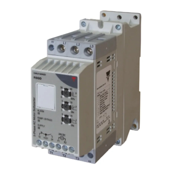
Chapter 1 Introduction 1.1 Foreword RSGD is a 2-phase controlled soft starter with a dedicated algorithm for general purpose applications. RSGD is equipped with Modbus RTU communication over RS485. The purpose of this document is to outline information on the functionalities that are provided by Modbus. -
Page 4: Chapter 2 Software Installation
Chapter 2 Software Installation 2.1 System requirements Software configuration software is designed to run on: • Windows 7 • Windows 8/8.1 • Windows 10 2.2 Software setup file If the PC meets the above system requirements, you can download the latest version setup_SCS_2.0.zip from... - Page 5 Choose a location to install the software or click next to continue with the default location. Click next to start the installation. Once the installation is complete, you should see the Carlo Gavazzi logo on your desktop. Double click to open the software. The following screen will appear:...
-
Page 6: Uninstalling The Software
2.3 Uninstalling When you uninstall the software, the files installed by SCS will be removed from your PC. the software The following steps instruct you to uninstall the software from your PC. ➢ Open the Control Panel in Windows and under Programs, click on Uninstall a program ➢... -
Page 7: Chapter 3 Establishing Communication
Chapter 3 Establishing Communication 3.1 Introduction The RSGD can be controlled either by a PC or by a controller using Modbus RTU protocol, with one-to-one or one-to-many communication. The Modbus link between the master and slaves can be established on a 3-wire RS485 communication port. -
Page 8: One-To-One Communication
One-to-one communication occurs between a PC with SCS (or a controller) and one RSGD. In order to establish one-to-one communication, the RSGD unit must be first powered-up with the specified supply voltage. If the supply LED is green fixed on the soft starter, you can establish communication with the soft starter. -
Page 9: One-To-Many Communication
One-to-many communication occurs between a PC (or a controller) and multiple general purpose soft starters. In order to establish one-to-many communication, the RSGD units must be first all powered-up with the specified supply voltage. If the supply LED is green fixed on the soft starter, you can establish communication with the soft starter. -
Page 10: Automatic Connection
In the event that communication is not established, the following message will be displayed: Please check that the following conditions are satisfied before trying to re- establish communication: ✓ RSGD softstarter/s is/are powered-up (Green fixed LED) ✓ RS485 port is properly connected ✓ Communication settings are correct... -
Page 11: Manual Connection
In the event that communication is not established, the following message will be displayed: Please check that the following conditions are satisfied before trying to re- establish communication: ✓ RSGD softstarter/s is/are powered-up (Green fixed LED) ✓ RS485 port is properly connected ✓ Communication settings are correct... -
Page 12: Chapter 4 Scs User Interface
Chapter 4 SCS User Interface 4.1 Software structure The soft starter configuration software can be used to configure, control and monitor RSGD soft starters. It consists of three main windows: • Dashboard • Settings • Variables The three main windows of the SCS can only be accessible when the PC establishes communication with the device. - Page 13 The functions provided by the Dashboard window are: a. Device This function consists of: ➢ Device On/Off command This command can be used to switch On/Off the control/start signal, if the Control Mode is set to Modbus control. The Control Mode parameter can be modified through the software from the Settings window under the Inputs section.
- Page 14 The Start Command Refresh and Refresh Interval parameters can be modified through the software from the Settings window under the Inputs section. ➢ Number of ramps This variable indicates the number of ramps (i.e. the number of starts) that the soft starter has successfully accomplished. ➢...
- Page 15 ➢ Alarm Reset The alarm reset mode can be: ✓ AUTO ✓ MANUAL ➢ Motor Overload Alarm & Phase Sequence Alarm The motor overload and phase sequnce can be: ✓ ENABLE ✓ DISABLE ➢ Remote Reset & PTC The remote reset and PTC can be: ✓...
- Page 16 d. Power Monitoring This function monitors either one of the following variables: ➢ Frequency (Hz) ➢ Active power (kW) ➢ Total apparent power (kVA) ➢ Reactive power (kVAr) ➢ Power factor (PF) ➢ Power (kWh) To select between the aforementioned variables, you must click on the upper right-hand corner of the widget and the following screen shall appear: e.
- Page 17 To select between the aforementioned variables, you must click on the upper right-hand corner of the widget and the following screen shall appear: Scope This function works the same way as an oscilloscope and it can monitor either one of the following variables: ➢...
- Page 18 g. Alarm Status If one of the eight alarms mentioned in Variables window is triggered the following screen will appear: The softstarter will not respond to a start command if it is in Alarm state. h. Sales/Engineering The following variables and settings are password protected: ➢...
- Page 19 To unlock these variables and settings, you must enter the correct access code. The access code can be obtained from Carlo Gavazzi sales support. If the access code is incorrect, the following message will be displayed:...
-
Page 20: Settings Window
4.4 Settings window The Settings window lists the programmable parameters available for the RSGD units. If you want to customise the unit for your own application, you will have to change the default factory parameter settings. Make sure that the RSGD is in idle state while parameters are modified. - Page 21 Communication In this function, the user can visualise and modify the communication parameters. The default communication parameters can be found in Chapter 3 Section 3.1. The communication parameters become effective only when the RSGD unit is turned OFF and ON.
- Page 22 d. Inputs In this function, the user can select the Control Mode (Modbus or A1 A2 mode) and can also enable/disable the Start Command Refresh (a.k.a. heartbeat signal). The factory default Control Mode is set to A1-A2 mode. If the Start Command Refresh is disabled, the load remains switched ON in case communication is lost.
- Page 23 (.xlsx) or CSV (.csv) format) which contains information about the last 32 starts performed. For further information on the content of the history file we advise you to contact Carlo Gavazzi sales support. g. Reset If an alarm is triggered, the Soft Alarm Reset can be used to reset...
-
Page 24: Variables Window
4.5 Variables window The Variables window lists the instantaneous variables and the counters available for the RSGD units. The functions provided by the Variables window are: a. Power Monitoring b. Operating... - Page 25 c. Voltage Monitoring d. Current Monitoring e. General Counters...
- Page 26 RSGD will trigger the voltage unbalance alarm. ➢ Internal Fault In case there is an internal fault in the RSGD circuitry, the soft starter will trip. ➢ Shorted SCR In case the RSGD detects that there is a damaged (shorted) thyristor (SCR) on any of the three phases, the soft starter will trip.
- Page 27 ➢ Phase Loss (Motor Side) If any of the phases on the load (motor) side becomes open the RSGD will trip after 5 seconds to protect the motor from running/ starting on 2 phases. ➢ Locked Rotor If a current ≥ 8xFLC setting for 100 msec is detected, the RSGD will trigger the locked rotor alarm.
-
Page 28: Chapter 5 Modbus Rtu Protocol
(called queries); the other devices (called slaves) respond with the requested data to the master. 5.2 Modbus RTU functions The following Modbus functions are available on the RSGD soft starters: ➢ Reading of n “Input register” (code 04h) ➢ Writing of one “holding register”... - Page 29 Response Frame (correct action): Description Length Value Note 1 byte Physical Address 1h to F7h (1 to 247) Function Code 1 byte Byte Count 1 byte N word * 2 Register Value N* 2 bytes Byte order: MSB, LSB 2 bytes Response Frame (incorrect action): Description Length...
-
Page 30: Registers Map
5.3 Registers Map Data Format Representation Format IEC data type Description Bits Range 0…65535 UINT16 UINT Unsigned integer Group Description Group Description Communication Includes the communication parameters of the device Parameters Indicates the settings of the three selector knobs Device Settings found on the device Describes the status of the soft starter and other Device Status... - Page 31 Write only mode (function 06h): Modicon Physical Length Data Notes Description Address Address (words) Format [Scaling Factor] 408193 2000h Device Address UINT16 Range: 0001h to 00F7h [x1] 0000h: 9600bps [x1] 0001h: 19200bps [x1] 408194 2001h Baud Rate UINT16 0002h: 38400bps [x1] 0003h: 57600bps [x1] 0h: No Parity, 2 stop bits [x1] 408195...
- Page 32 Notes [Scaling Factor] Modicon Physical Length Data Description Address Address (words) Format No of Alarm Status Flashes Internal fault Wrong phase sequence Line voltage out of range Phase loss (motor side) Locked rotor Over temperature Overload Supply voltage unbalance Shorted SCR 0000h: Auto alarm reset 320489 5008h...
- Page 33 Force Refresh Signal enabled, this register has to 428677 7004h UINT16 (Heartbeat Signal) be set to 1 within every refresh interval otherwise the RSGD unit will switch OFF the output. Delays Read only mode (function 04h): Modicon Physical Length Description...
- Page 34 Write only mode (function 06h): Modicon Physical Length Data Notes Description Address Address (words) Format [Scaling Factor] Enable or Disable the phase sequence alarm Phase Sequence alarm 440966 A005h UINT16 mode 0000h: Enable 0001h: Disable Enable or Disable the motor overload alarm Motor overload alarm 440967...
- Page 35 Modicon Physical Length Data Notes Description Address Address (words) Format [Scaling Factor] Supply Voltage Supply Voltage Unbalance 324586 6009h UINT16 Unbalance [x1] General Counters Read only mode (function 04h): Modicon Physical Length Data Notes Description Address Address (words) Format [Scaling Factor] 316385 4000h UINT16...
- Page 36 Notes Modicon Physical Length Data Description [Scaling Factor] Address Address (words) Format Line current (L3) during 316646 4105h I L3 Bypass (A UINT16 bypass [X10] Line current (L1) during 316647 4106h I L1 Ramp-down (A UINT16 ramp-down [X10] Line current (L2) during 316648 4107h I L1 Ramp-down (A...
-
Page 37: Chapter 6 Examples
RSGD unit. Step 1: Go to the Settings window. Step 2: Click on the Communication settings. Step 3: Change the communication parameters as desired. The communication parameters become effective only when the RSGD unit is turned OFF and ON. -
Page 38: Start/Stop Through Modbus
6.2 Start/Stop through Modbus The following example shows how the user can start and stop the RSGD unit through Modbus. Step 1: Go to the Settings window. Step 2: Click on the Inputs settings, set the Control Mode to Modbus Mode and click save. -
Page 39: Start/Stop Using Force Refresh Signal
6.3 Start/Stop using Force Refresh Signal The following example shows how the user can start and stop the RSGD unit using force refresh signal. Step 1: Go to the Settings window. Step 2: Click on the Inputs settings, set the Control Mode to Modbus Mode, enable the Start Command Refresh, set the Refresh Interval and click save. - Page 40 Step4: During the Refresh Interval, click on the Refresh Command button so that the load remains on. Step 5: Do not click on the Refresh Command button when you want to stop the load.
-
Page 41: Appendix
Data of Start 1 in Little Endian format bytes * All data received is expressed in hexadecimal. Example: Read the data of the last 32 starts recorded in the RSGD memory. Step 1: Read data from address C000h Request Frame: Description... - Page 42 Response Frame (correct action): Description Value Physical Address Function Code Byte Count Register Value 0100AF8741020F91008030080000990400000 0000000750C00802008484900200200AF8741 020F910080300800009904000000000000750 C00802008484900200300AF8741020F91008 0300800009904000000000000750C00802008 484900200400AF8741020F910080300800009 904000000000000750C0080200848490020h Response Frame (incorrect action): Description Value Physical Address Function Code Exception Code 01h, 02h, 03h Step 2: Divide the received data into four blocks of 32bytes of data Start 1: 0100AF8741020F910080300800009904000000000000750C0080200848490020h Start 2: 0200AF8741020F910080300800009904000000000000750C0080200848490020h Start 3: 0300AF8741020F910080300800009904000000000000750C0080200848490020h...
- Page 43 LSB11 MSB11 LSB12 MSB12 LSB13 MSB13 LSB14 MSB14 LSB15 MSB15 LSB16 MSB16 * Two hexadecimal digits represent one byte. Step 4: By using the conversion formula convert each byte to display information of the respective start. Code Variable Description Start number The start number to which the data belongs System voltage &...
- Page 44 Step 5: Repeat the above procedure for another 3 times to convert the data of the first 4 starts recorded in the RSGD memory. Step 6: Repeat steps 1 to step 5 for another 7 times to convert the data of the last 32 starts recorded in the...
- Page 45 Data Representation: Code Format LSB1 MSB1 Bits Code Variable Conversion Statement Comments - Convert MSB1 to decimal, multiply by 256 and �� store the result in variable Start - Convert LSB1 to decimal and store the result in Number �� variable ��...
- Page 46 Code Format LSB3 MSB3 Bits Code Variable Conversion Statement Comments - Convert MSB3 to binary, bitwise-AND by �� 0b00001111 and store the result in variable Current �� - Convert to decimal, multiply by 256 and store Balancing �� Scaling Factor: +32423 the result in variable - Convert LSB3 to decimal and store the result in Setting...
- Page 47 Code Variable Conversion Statement Comments Value Ramp-down time (s) - Convert MSB4 to binary, bitwise-AND by �� 0b00111000 and store the result in variable �� - Rhift arithmetic right by 3 and store the result in Ramp-down �� variable time ��...
- Page 48 - Convert LSB6 to binary, bitwise-AND 0b00001111, left arithmetic shift by 6 and store �� the result in variable Max IL3 - Convert MSB6 to binary, right arithmetic shift by 2 during �� and store the result in variable ramp-up ��...
- Page 49 Code Format LSB9 MSB9 Bits Code Format LSB10 MSB10 Bits Code Variable Conversion Statement Comments - Convert LSB9 to binary, left arithmetic shift by 2 �� and store the result in variable - Convert MSB9 to binary, right arithmetic shift by 6 Max IL1 ��...
- Page 50 Code Format LSB11 MSB11 Bits Code Variable Conversion Statement Comments - Convert MSB11 to decimal, multiply by 256 �� and store the result in variable Torque on - Convert LSB11 to decimal and store the Scaling Factor: x40 leaving bypass ��...
- Page 51 Code Variable Conversion Statement Comments - Convert LSB13 to binary, left arithmetic shift by 2 �� and store the result in variable Max IL1 - Convert MSB13 to binary, right arithmetic shift by 6 �� and store the result in variable during ramp- ��...
- Page 52 Code Format LSB16 MSB16 Bits Code Variable Conversion Statement Comments Estimated - Convert LSB16 to decimal and store the �� result in variable Motor Scaling Factor: -40 �� - Conversion result = Temperature Code Variable Conversion Statement Comments Value State Internal fault Spare Spare...
Need help?
Do you have a question about the RSGD and is the answer not in the manual?
Questions and answers