CARLO GAVAZZI VariFlex3 RVFF Series Manual
Motor controllers ac variable frequency drives
Hide thumbs
Also See for VariFlex3 RVFF Series:
- Manual (372 pages) ,
- Quick start manual (99 pages) ,
- Quick start manual (40 pages)
Advertisement
Quick Links
Advertisement

Related Manuals for CARLO GAVAZZI VariFlex3 RVFF Series


Summary of Contents for CARLO GAVAZZI VariFlex3 RVFF Series
- Page 1 Motor Controllers AC Variable Frequency Drives Type VariFlex RVFF...
- Page 2 Motor Controllers AC Variable Frequency Drives Type Variflex RVFF Contents Preface ........................5 Chapter 1 Safety Precautions ................. 6 1.1 Before Supplying Power to the Inverter ................. 6 1.2 Wiring ............................ 7 1.3 Before Operation ........................8 1.4 Parameter Setting........................8 1.5 During Operation ........................
- Page 3 Motor Controllers AC Variable Frequency Drives Type Variflex RVFF 3.10 Terminal Description ......................34 3.10.1 Main Circuit Terminals ....................34 3.10.2 Control Circuit Terminals ..................... 36 3.11 Inverter Dimension ......................38 Chapter 4 Keypad and Programming Functions ..........42 4.1 LED Keypad ........................42 4.1.1 Keypad Display and Keys .....................
- Page 4 Motor Controllers AC Variable Frequency Drives Type Variflex RVFF 6.2 Reference from External Analog Signal (0-10V / 4-20mA) ........ 355 6.3 Reference from Serial Communication RS485 (00-05=3) ..........357 6.4 Reference from two Analog Inputs ..................359 6.5 Change Frequency Unit from Hz to rpm ................359 Chapter 7 Operation Method Configuration (Run/Stop) ........
- Page 5 Motor Controllers AC Variable Frequency Drives Type Variflex RVFF 11.6.1 Introduction ....................... 410 11.6.2 Wiring Diagram of RV-PDP ..................411 11.6.3 Installation ......................... 412 11.6.4 Descriptions of Terminals, LEDs and DIP switch ............413 11.6.5 Related Parameters for Communication ..............414 11.6.6 Profibus I/O List ......................
- Page 6 Motor Controllers AC Variable Frequency Drives Type Variflex RVFF Preface The RVFF product is an inverter designed to control three-phase induction and permanent magnet synchronous motors. Please read this manual carefully to ensure correct operation, safety and to become familiar with the inverter functions. The RVFF inverter is an electrical/electronic product and must be installed and handled by qualified service personnel.
- Page 7 Motor Controllers AC Variable Frequency Drives Type Variflex RVFF Chapter 1 Safety Precautions 1.1 Before Supplying Power to the Inverter Warning ➢ The main circuit must be wired correctly before operated. Input terminals (R/L1, S/L2, T/L3) must be connected with three phase supply and terminals U/T1, V/T2, W/T3 must only be used to connect the motor.
- Page 8 Motor Controllers AC Variable Frequency Drives Type Variflex RVFF 1.2 Wiring Warning ➢ Always turn OFF the power supply before attempting inverter installation and wiring of the user terminals. ➢ Wiring must be performed by a qualified personnel/certified electrician. ➢ Make sure the inverter is properly grounded (grounding impedance shall be less than 10Ω).
- Page 9 Motor Controllers AC Variable Frequency Drives Type Variflex RVFF 1.3 Before Operation Warning ➢ Ensure the inverter capacity matches the parameters 13-00 before supplying power. ➢ Reduce the carrier frequency (parameter 11-01) if the cable from the inverter to the motor is over 80 ft.
- Page 10 Motor Controllers AC Variable Frequency Drives Type Variflex RVFF ➢ An external emergency stop switch is enabled when parameter 08-30 is set for the run permissive function. ➢ It provides an independent external hardware emergency switch, which emergently shuts down the inverter output in the case of danger. ➢...
- Page 11 Motor Controllers AC Variable Frequency Drives Type Variflex RVFF 1.6 Maintenance, Inspection and Replacement Warning ➢ Ensure a minimum delay of 5 minutes after power has been turned OFF before starting an inspection. Also confirm that the charge light is OFF and that the DC bus voltage has dropped below 25Vdc.
- Page 12 Motor Controllers AC Variable Frequency Drives Type Variflex RVFF Chapter 2 Model Description 2.1 Nameplate Data It is essential to verify the RVFF inverter nameplate and make sure that the RVFF inverter has the correct rating so it can be used in the desired application with the proper sized AC motor. Unpack the RVFF inverter and check the following: (1) The RVFF inverter and the quick setting guide are contained in the package.
- Page 13 Motor Controllers AC Variable Frequency Drives Type Variflex RVFF Inverter Models – Motor Power Rating Horse Filter Nominal Input Voltage RVFF Model Power Rating Motor Power Range with without (kW) (HP) ◎ RVFFA3400400F ◎ RVFFA3400550F ◎ RVFFA3400750F ◎ RVFFB3401100F ◎ RVFFB3401500F ◎...
- Page 14 Motor Controllers AC Variable Frequency Drives Type Variflex RVFF Chapter 3 Environment and Installation 3.1 Environment The environment will directly affect the proper operation and the life span of the inverter. To ensure that the inverter will give maximum service life, please comply with the following environmental conditions: Protection Protection...
- Page 15 Motor Controllers AC Variable Frequency Drives Type Variflex RVFF 3.2 Installation 3.2.1 Installation Spaces When installing the inverter, ensure that inverter is installed in upright position (vertical direction) and there is adequate space around the unit to allow normal heat dissipation as per the following Fig. 3.2.1 5.9in.
- Page 16 Motor Controllers AC Variable Frequency Drives Type Variflex RVFF 3.2.2 Inverter Derating Based on Carrier Frequency Curves below show the applicable output current de-rate due to setting of carrier frequency. Rated Current Model 0400 0550 0750 1100 400V 5~30HP Ratio 100% 83% 85% 78% 100% 60% 50% 51% 47%...
- Page 17 Motor Controllers AC Variable Frequency Drives Type Variflex RVFF Rated Current 400V 75~215HP Ratio 100% Model 5500 7500 9000 88% 81% 91% 62% 57% 64% Model 11000 13200 16000 87% 86% 88% 61% 60% 61% Carrier Frequency (Fc) 4KHz 5KHz 10KHz 1616KHz ◆...
- Page 18 Motor Controllers AC Variable Frequency Drives Type Variflex RVFF 3.3 Wiring Guidelines • Do NOT remove any protective covers or attempt any wiring while input power is applied. Connect all wiring before applying input power. When making wiring changes after power up, remove input power and wait a minimum of five minutes after power has been turned off before starting.
- Page 19 Motor Controllers AC Variable Frequency Drives Type Variflex RVFF 3.3.3 Cable Size and Length ◼ Cable Size The following table shows the recommended cable size for each of the RVFF models. RVFF Model Wire size (mm Power Horse power Rated Rated Main Grounding...
- Page 20 Motor Controllers AC Variable Frequency Drives Type Variflex RVFF ◼ Wiring Gauges and Tightening Torque To comply with UL standards, use UL approved copper wires (rated 75° C) and round crimp terminals (UL Listed products) as shown in table below when connecting to the main circuit terminals. Carlo Gavazzi recommends using crimp terminals manufactured by NICHIFU Terminal Industry Co., Ltd and the terminal crimping tool recommended by the manufacturer for crimping terminals and the insulating sleeve.
- Page 21 Motor Controllers AC Variable Frequency Drives Type Variflex RVFF 3.3.4 Grounding (1) Connect the ground terminal (E) to ground having a resistance of less than 100Ω. (2) Do not share the ground wire with other equipments, such as welding machines or power tools.
- Page 22 ⚫ A filter must be installed when there are inductive loads affecting the inverter. The inverter meets EN55011 Class A, category C3 when the Ground Carlo Gavazzi special filter is used. See section 11.3 for peripheral devices. Inverter: ⚫ Output terminals T1, T2, and T3 are connected to U, V, and W Output Noise terminals of the motor.
- Page 23 Motor Controllers AC Variable Frequency Drives Type Variflex RVFF Caution After power is shut off to the inverter, the capacitors will slowly discharge. Do NOT touch the ⚫ inverter circuitry or replace any components until the “CHARGE” indicator is off. Do NOT wire or connect/disconnect internal connectors of the inverter when the inverter is ⚫...
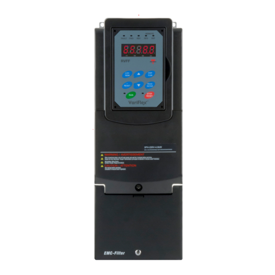
- Page 24 Motor Controllers AC Variable Frequency Drives Type Variflex RVFF 3.5 Inverter External View 400V 5-10HP Wall-mounted type, IEC IP20, NEMA1 400V 15-40HP Wall-mounted type, IEC IP20, NEMA1 Specifications are subjected to change without notice.
- Page 25 Motor Controllers AC Variable Frequency Drives Type Variflex RVFF 400V 50-75HP Wall-mounted type, IEC IP20, NEMA1 400V 100-215HP Wall-mounted type, IEC IP20, NEMA1 Specifications are subjected to change without notice.
- Page 26 Motor Controllers AC Variable Frequency Drives Type Variflex RVFF 3.6 Warning Labels Important: Warning information located on the front cover must be read upon installation of the inverter. (a) 400V: 5-10HP (IP20) (b) 400V: 15-20HP (IP20) 400V: 25-215HP(IP20) Specifications are subjected to change without notice.
- Page 27 Motor Controllers AC Variable Frequency Drives Type Variflex RVFF 3.7 Removing the Front Cover and Keypad Before making any wiring connections to the inverter, the front cover needs to be removed. Caution ◼ It is not required to remove the digital operator before making any wiring connections. ◼...
- Page 28 Motor Controllers AC Variable Frequency Drives Type Variflex RVFF 3.7.1 Built-in Filter Type 400V: 5-75HP Step 1: Unscrew cover Step 2: Remove cover Step 3: Unscrew filter section Step 4: Remove filter cover Step 5: Make connections and Step 6: Fasten screw place filter cover back Specifications are subjected to change without notice.
- Page 29 Motor Controllers AC Variable Frequency Drives Type Variflex RVFF 3.7.2 No Built-in Filter Type 400V: 100-215HP Step 1: Unscrew cover Step2: Remove cover Step 3: Make wire connections Step 4: Fasten screw and place cover back Specifications are subjected to change without notice.
- Page 30 Motor Controllers AC Variable Frequency Drives Type Variflex RVFF 3.8 Specifications 3.8.1 Product Specifications 100 125 Inverter capacity (HP) Rated Output Capacity 13.3 17.5 23.6 28.9 33.5 41.1 54.8 67 78.4 110 (KVA) Rated Output Current (A) 12.1 17.5 103 145 Maximum Applicable (3.7) (5.5)
- Page 31 Motor Controllers AC Variable Frequency Drives Type Variflex RVFF 3.8.2 General Specifications Operation Modes LED keypad with seven-segment display Control Modes V/F, SLV, PMSLV with space vector PWM mode 0.1Hz~400.0Hz Frequency Control Range Frequency Accuracy Digital references: ±0.01% (-10 to +40℃), analog references: ±0.1% (25℃±10℃) (Temperature change) Speed Control Accuracy ±0.5%...
- Page 32 Motor Controllers AC Variable Frequency Drives Type Variflex RVFF 3.9 General Wiring Diagram The following is the standard wiring diagram for the RVFF inverter (◎ indicates main circuit terminals and ○ indicates control circuit terminals). Locations and symbols of the wiring terminal block might be different due to different models of RVFF.
- Page 33 Motor Controllers AC Variable Frequency Drives Type Variflex RVFF 3.9.1 Input/Output Power Section Block Diagram The following diagrams show the basic configuration of the power sections for the range of horsepower and input voltages. This is shown for reference only and is not a detailed depiction. 400V: 5~40HP 400V: 50~75HP ○...
- Page 34 Motor Controllers AC Variable Frequency Drives Type Variflex RVFF 3.9.2 Cooling Fan Supply Voltage Selection (400V class) The inverter input voltage range of the RVFF 400V class models ranges from 380 to 480Vac. In these models the cooling fan is directly powered from the power supply. Inverter models RVFF- 3409000/34011000/34013200/34016000 requires the user to select the correct jumper position based on the inverter input voltage ("440V"...
- Page 35 Motor Controllers AC Variable Frequency Drives Type Variflex RVFF 3.10 Terminal Description 3.10.1 Main Circuit Terminals Terminal 400V:5~40HP 400V: 50~215HP R/L1 S/L2 Input power supply T/L3 B1/P • B1/P-:DC power supply • B1/P-B2:external braking resistor • -:DC power supply ...
- Page 36 Motor Controllers AC Variable Frequency Drives Type Variflex RVFF 400V: 25-40HP Terminal screw size 400V: 50-75HP Terminal screw size 400V: 100-125HP Terminal screw size Power supply 400V 100HP 400V 125HP 400V: 150-215HP Terminal screw size Specifications are subjected to change without notice.
- Page 37 Motor Controllers AC Variable Frequency Drives Type Variflex RVFF 3.10.2 Control Circuit Terminals Type Terminal Terminal function Signal level/Information Signal Level 24 VDC Digital (opto-isolated) input Multi-function input terminals Maximum current: 8mA signal Maximum voltage: 30 VDC Input impedance: 4.22kΩ Common point of digital signal SOURCE ±15%, Max.
- Page 38 Motor Controllers AC Variable Frequency Drives Type Variflex RVFF 400V: 5HP-75HP S(+) S(-) +10V 24VG 400V: 100HP~215HP S(+) S(-) +10V 24VG Caution ◼ Maximum output current capacity for terminal 10V is 20mA. ◼ Multi-function analogue output AO1 and AO2 are for use for an analogue output meter. Do not use these output for feedback control.
- Page 39 Motor Controllers AC Variable Frequency Drives Type Variflex RVFF 3.11 Inverter Dimension (a) 400V 5-10HP Dimensions in mm (inch) Inverter Model NW in kg(lbs) RVFFA3400400F (5.51) (15.16) (6.97) (4.80) (10.51) (10.98) (0.28) (12.13) RVFFA3400550F (5.51) (15.16) (6.97) (4.80) (10.51) (10.98) (0.28) (12.13) RVFFA3400750F...
- Page 40 Motor Controllers AC Variable Frequency Drives Type Variflex RVFF (b) 400V: 15-40HP Dimensions in mm (inch) Inverter Model NW in kg(lbs) 416.5 RVFFB3401100F (8.27) (16.40) (8.46) (7.56) (11.26) (11.81) (0.06) (17.64) 416.5 RVFFB3401500F (8.27) (16.40) (8.46) (7.56) (11.26) (11.81) (0.06) (17.64) 12.5 RVFFC3401850F...
- Page 41 Motor Controllers AC Variable Frequency Drives Type Variflex RVFF (c) 400V: 50-75HP Dimensions in mm (inch) Inverter Model NW in kg(lbs) 32.5 RVFFD3403700F (11.18) (26.73) (9.92) (8.66) (19.88) (20.67) (0.06) (71.65) 32.5 RVFFD3404500F (11.18) (26.73) (9.92) (8.66) (19.88) (20.67) (0.06) (71.65) 32.5 RVFFD3405500F...
- Page 42 Motor Controllers AC Variable Frequency Drives Type Variflex RVFF (d) 400V: 100-250HP Dimensions in mm (inch) Inverter Model NW in kg(lbs) 348.5 RVFFE3407500 (13.72) (29.13) (11.81) (9.84) (22.05) (0.06) (97.00) 348.5 RVFFE3409000 (13.72) (29.13) (11.81) (9.84) (22.05) (0.06) (97.00) 463.5 1105 324.5 RVFFF34011000...
- Page 43 Motor Controllers AC Variable Frequency Drives Type Variflex RVFF Chapter 4 Keypad and Programming Functions 4.1 LED Keypad 4.1.1 Keypad Display and Keys Reverse Direction Local/Remote Forward Direction Status Indicator Status Indicator Indicator External Reference Fault Status Indicator Indicator External Sequence Indicator 5 Digit, 7 Segment LED Display...
- Page 44 Motor Controllers AC Variable Frequency Drives Type Variflex RVFF KEYS (8) Description RUN inverter STOP STOP inverter ▲ Parameter navigation Up, increase parameter or reference value ▼ Parameter navigation down, decrease parameter or reference value Used switch between local mode remote mode REMOTE Mode: set by parameters, controlled by control circuit terminals,...
- Page 45 Motor Controllers AC Variable Frequency Drives Type Variflex RVFF 4.1.2 Seven Segment Display Description Actual LED Display Actual LED Display Actual LED Display Actual LED Display ° Display output frequency Frequency reference Set frequency reference LED lights on LED flashes Flashing digit ◆...
- Page 46 Motor Controllers AC Variable Frequency Drives Type Variflex RVFF LED Display Examples Seven Segment Display Description 1. Displays the frequency reference at power-up. 2. Displays the actual output frequency during run operation. Displays parameter code. Displays the setting value of parameter. Displays input voltage.
- Page 47 Motor Controllers AC Variable Frequency Drives Type Variflex RVFF 4.1.3 LED Indicator Description ⚫ Fault LED State Description FAULT LED No fault active Illuminated Fault active ⚫ Forward LED State Description FWD LED Inverter in reverse direction Illuminated Inverter is running in forward direction Flashing Forward direction active, no run command ⚫...
- Page 48 Motor Controllers AC Variable Frequency Drives Type Variflex RVFF ⚫ REF LED State Description REF LED Frequency reference set from keypad Illuminated Frequency reference set from external source Run/Stop Status Indicators Output Frequency STOP STOP Frequency Setting STOP Flashing Specifications are subjected to change without notice.
- Page 49 Motor Controllers AC Variable Frequency Drives Type Variflex RVFF 4.1.4 Power-up Monitor ◆ Power-up DSP/FUN DSP/FUN After 3 sec. Switch Mode Display at Power-up Frequency Reference Parameter Selection ◆ Changing Monitor at Power-up 12-00 Display Selection Highest bit -> 0 0 0 0 0 <- Lowest bit The setting range for each bit is 0~7 from the highest bit to the lowest bit.
- Page 50 Motor Controllers AC Variable Frequency Drives Type Variflex RVFF Example: 12-00=【12345】 DSP/FUN Heatsink Temperature <4> DSP/FUN DSP/FUN DC Voltage <3> Output Voltage <2> PID Feedback <5> DSP/FUN DSP/FUN After 3 sec. Display Voltage Class Output Current <1> Parameter Selection at Power-up DSP/FUN DSP/FUN Frequency Reference...
- Page 51 Motor Controllers AC Variable Frequency Drives Type Variflex RVFF Example: Set Frequency Reference Inverter stopped: Inverter is running: Display Voltage Class Display Voltage Class Flashing for 3 seconds Flashing for 3 seconds Display Frequency Reference ▲ Display Frequency Reference Press Press RUN 1x Press </RESET Output Frequency...
- Page 52 Motor Controllers AC Variable Frequency Drives Type Variflex RVFF 4.1.6 Operation Control Stopped Running Stopping Stopped Output Frequency Indicator Indicator Indicator STOP Indicator STOP STOP STOP STOP STOP STOP STOP STOP Specifications are subjected to change without notice.
- Page 53 Motor Controllers AC Variable Frequency Drives Type Variflex RVFF 4.2 Programmable Parameter Groups Parameter Group Name Group 00 Basic Parameters Group 01 V/F Control Parameters Group 02 IM Motor Parameters Group 03 External Digital Input and Output Parameters Group 04 External Analogue Input and Output Parameters Group 05 Multi-Speed Parameters...
- Page 54 Motor Controllers AC Variable Frequency Drives Type Variflex RVFF Group 00 Basic Parameters Control Mode Attribute Code Parameter Name Setting Range Default Unit V/F SLV PM 0: V/F 1: Reserved 2: SLV 00-00 Control mode selection 3~4: Reserved 5: PM SLV 0: Forward 00-01 Motor’s rotation direction 1: Reverse...
- Page 55 Motor Controllers AC Variable Frequency Drives Type Variflex RVFF Group 00 Basic Parameters Control Mode Attribute Code Parameter Name Setting Range Default Unit V/F SLV PM 00-13 Frequency lower limit 0.0~109.0 00-14 Acceleration time 1 0.1~6000.0 10.0 00-15 Deceleration time 1 0.1~6000.0 10.0 00-16 Acceleration time 2...
- Page 56 Motor Controllers AC Variable Frequency Drives Type Variflex RVFF Group 01 V/F Control Parameters Control Mode Attribute Code Parameter Name Setting Range Default Unit V/F SLV PM 01-09 Minimum output voltage 0.0~510.0 13.2 01-10 Torque compensation gain 0.0~2.0 0: mode 0 01-11 Torque compensation mode 1: mode 1 01-12 Base frequency...
- Page 57 Motor Controllers AC Variable Frequency Drives Type Variflex RVFF Group 03 External Digital Input and Output Parameters Control Mode Attribute Code Parameter Name Setting Range Default Unit V/F SLV PM 1: 2-Wire sequence (Reverse run command) 2: Multi-Speed setting command 1 3: Multi-Speed setting command 2 4: Multi-Speed setting command 3 5: Multi-Speed setting command 4...
- Page 58 Motor Controllers AC Variable Frequency Drives Type Variflex RVFF Group 03 External Digital Input and Output Parameters Control Mode Attribute Code Parameter Name Setting Range Default Unit V/F SLV PM 35: Timing function input 36: PID soft start disable Multi-function terminal 41: PID sleep 03-04 function setting-S5...
- Page 59 Motor Controllers AC Variable Frequency Drives Type Variflex RVFF Group 03 External Digital Input and Output Parameters Control Mode Attribute Code Parameter Name Setting Range Default Unit V/F SLV PM 4: Frequency detection 1 (> 03-13) 5: Frequency detection 2 (< 03-13) 6: Automatic restart 7~8: Reserved 9: Baseblock...
- Page 60 Motor Controllers AC Variable Frequency Drives Type Variflex RVFF Group 03 External Digital Input and Output Parameters Control Mode Attribute Code Parameter Name Setting Range Default Unit V/F SLV PM 03-13 Frequency detection level 0.0~400.0 03-14 Frequency detection width 0.1~25.5 03-15 Current agree level 0.1~999.9 03-16 Current agree detection...
- Page 61 Motor Controllers AC Variable Frequency Drives Type Variflex RVFF Group 03 External Digital Input and Output Parameters Control Mode Attribute Code Parameter Name Setting Range Default Unit V/F SLV PM 03-49 Low Current Detection 0.00~655.34 0.01 Delay Time 03-50 Frequency Detection Level 0.0~400.0 03-51 Frequency Detection Level 0.0~400.0...
- Page 62 Motor Controllers AC Variable Frequency Drives Type Variflex RVFF Group 04 External Analogue Input and Output Parameters Control Mode Attribute Code Parameter Name Setting Range Default Unit V/F SLV PM 4: Output current 5: Output power 6: Motor speed 7: Output power factor 8: AI1 Input 9: AI2 Input 10: Torque command...
- Page 63 Motor Controllers AC Variable Frequency Drives Type Variflex RVFF Group 05 Multi-Speed Function Group Control Mode Attribute Code Parameter Name Setting Range Default Unit V/F SLV PM 0: Acceleration and deceleration time are set by 1~4 05-00 Acceleration and deceleration selection of Multi-Speed 1: Acceleration and deceleration time setting respectively...
- Page 64 Motor Controllers AC Variable Frequency Drives Type Variflex RVFF Group 05 Multi-Speed Function Group Control Mode Attribute Code Parameter Name Setting Range Default Unit V/F SLV PM 05-22 Deceleration time setting of 0.1~6000.0 10.0 multi speed 2 05-23 Acceleration time setting of 0.1~6000.0 10.0 multi speed 3...
- Page 65 Motor Controllers AC Variable Frequency Drives Type Variflex RVFF Group 05 Multi-Speed Function Group Control Mode Attribute Code Parameter Name Setting Range Default Unit V/F SLV PM 05-45 Acceleration time setting of 0.1~6000.0 10.0 Multi speed 14 05-46 Deceleration time setting of 0.1~6000.0 10.0 multi speed 14...
- Page 66 Motor Controllers AC Variable Frequency Drives Type Variflex RVFF Automatic Program Operation Parameters Group 06 Control Mode Attribute Code Parameter Name Setting Range Default Unit V/F SLV PM Run freq. setting of speed- 06-07 0.00~400.00 50.00 stage 7 Run freq. setting of speed- 06-08 0.00~400.00 5.00...
- Page 67 Motor Controllers AC Variable Frequency Drives Type Variflex RVFF Automatic Program Operation Parameters Group 06 Control Mode Attribute Code Parameter Name Setting Range Default Unit V/F SLV PM Operation time setting of 06-30 0.0~6000.0 speed-stage 14 Operation time setting of 06-31 0.0~6000.0 speed-stage 15...
- Page 68 Motor Controllers AC Variable Frequency Drives Type Variflex RVFF Group 07 Start /Stop Parameters Control Mode Attribute Code Parameter Name Setting Range Default Unit V/F SLV PM 0: Enable direct running after power up 07-04 Direct running after power up 1: Disable direct running after power up 07-05 Direct starting delay-on timer...
- Page 69 Motor Controllers AC Variable Frequency Drives Type Variflex RVFF Group 07 Start /Stop Parameters Control Mode Attribute Code Parameter Name Setting Range Default Unit V/F SLV PM 0: Disable 1: Mode1: Start a Speed Search at 07-32 Speed Search Mode Selection Power on 2: Mode 2: Start Speed Search upon the Motor Run...
- Page 70 Motor Controllers AC Variable Frequency Drives Type Variflex RVFF Group 08 Protection Parameters Control Mode Code Parameter Name Setting Range Default Unit Attribute V/F SLV Start-up mode of overload 1: Continuous operation protection operation 0: Level 0 Motor overload (OL1) 08-07 1: Level 1 protection level...
- Page 71 Motor Controllers AC Variable Frequency Drives Type Variflex RVFF Group 08 Protection Parameters Control Mode Code Parameter Name Setting Range Default Unit Attribute V/F SLV 08-31 Reserved 08-34 0: Disable 08-35 Motor overheat selection 1: Deceleration to stop 2: Coast to stop 08-36 PTC input filter time 0.00~5.00 2.00...
- Page 72 Motor Controllers AC Variable Frequency Drives Type Variflex RVFF Group 09 Communication Parameters Control Mode Code Parameter Name Setting Range Default Unit Attribute V/F SLV INV communication station 09-00 1~31 address 0: MODBUS 1: BACNET Communication mode 09-01 selection 2: METASYS 3: PUMP in parallel connection 4: PROFIBUS 0:1200...
- Page 73 Motor Controllers AC Variable Frequency Drives Type Variflex RVFF Group 10 PID Parameters Control Mode Code Parameter Name Setting Range Default Unit Attribute V/F SLV 2:AI2 PID feedback value source 3: Reserved setting 4: AI1 – AI2 given 10-02 PID Target value 0.0~100.0 xxx0b: PID Disable xxx1b: PID Enable...
- Page 74 Motor Controllers AC Variable Frequency Drives Type Variflex RVFF Group 10 PID Parameters Control Mode Code Parameter Name Setting Range Default Unit Attribute V/F SLV 3: Reserved 10-33 PID feedback max. 1~10000 10-34 PID decimal width 0: % 1: FPM 2: CFM 3: PSI 4: GPH...
- Page 75 Motor Controllers AC Variable Frequency Drives Type Variflex RVFF Group 11 Auxiliary Parameters Control Mode Code Parameter Name Setting Range Default Unit Attribute V/F SLV 0: Allow forward and reverse rotation 11-00 Motor direction lock selection 1: Only allow forward rotation 2: Only allow reverse rotation 0: Carrier output frequency tuning Inverter...
- Page 76 Motor Controllers AC Variable Frequency Drives Type Variflex RVFF Group 11 Auxiliary Parameters Control Mode Code Parameter Name Setting Range Default Unit Attribute V/F SLV Variable carrier frequency min. 11-31 2~16 limit Variable carrier frequency 11-32 00~99 proportional gain Rise Amount of DC Voltage 11-33 0.1~10.0 *1 *7...
- Page 77 Motor Controllers AC Variable Frequency Drives Type Variflex RVFF Group 11 Auxiliary Parameters Control Mode Code Parameter Name Setting Range Default Unit Attribute V/F SLV 0: When UP/DOWN in keypad is disabled, it will be enabled if press ENTER after frequency 11-56 UP/DOWN Selection modification.
- Page 78 Motor Controllers AC Variable Frequency Drives Type Variflex RVFF Group 12 Monitoring Parameters Control Mode Code Parameter Name Setting Range Default Unit Attribute V/F SLV 00000~77777 From the leftmost bit, it displays the screen when press DSP key in order. 0: No display 1: Output current 12-00 Display screen selection...
- Page 79 Motor Controllers AC Variable Frequency Drives Type Variflex RVFF Group 12 Monitoring Parameters Control Mode Code Parameter Name Setting Range Default Unit Attribute V/F SLV 12-06 Reserved 12-10 Display the output current of 12-11 Output current of present fault current fault Display the output voltage of 12-12 Output voltage of present fault current fault...
- Page 80 Motor Controllers AC Variable Frequency Drives Type Variflex RVFF Group 12 Monitoring Parameters Control Mode Code Parameter Name Setting Range Default Unit Attribute V/F SLV Display input error of the PID controller (PID target value - PID feedback) 12-36 PID Input (100% corresponds to the maximum frequency set by 01-02 or 01-16)
- Page 81 Motor Controllers AC Variable Frequency Drives Type Variflex RVFF Group 12 Monitoring Parameters Control Mode Code Parameter Name Setting Range Default Unit Attribute V/F SLV Display DI/DO status of previous 12-59 DI/DO status of previous fault fault description is similar to 12-05 Inverter status of previous Display inverter status of previous 12-60...
- Page 82 Motor Controllers AC Variable Frequency Drives Type Variflex RVFF Group 13 Maintenance Function Group Control Mode Code Parameter Name Setting Range Default Unit Attribute V/F SLV 0: Only parameter 13-06 and frequency setting parameters in main screen are writable 13-06 Parameters locked 1: Only user parameter is enabled.
- Page 83 Motor Controllers AC Variable Frequency Drives Type Variflex RVFF Group 13 Maintenance Function Group Control Mode Code Parameter Name Setting Range Default Unit Attribute V/F SLV Display Previous Three Fault 13-23 Previous Three Fault Message Message Display Previous Four Fault 13-24 Previous Four Fault Message Message Display Previous Five Fault...
- Page 84 Motor Controllers AC Variable Frequency Drives Type Variflex RVFF Group 13 Maintenance Function Group Control Mode Code Parameter Name Setting Range Default Unit Attribute V/F SLV Previous Twenty Eight Fault Display Previous Twenty Eight 13-48 Message Fault Message Previous Twenty Nine Fault Display Previous Twenty Nine 13-49 Message...
- Page 85 Motor Controllers AC Variable Frequency Drives Type Variflex RVFF Group 14 PLC Setting Parameters Control Mode Code Parameter Name Setting Range Default Unit Attribute V/F SLV 14-40 MD2 Set value 2 0~65534 14-41 MD2 Set value 3 0~65534 14-42 MD3 Set value 1 0~65534 14-43 MD3 Set value 2 0~65534...
- Page 86 Motor Controllers AC Variable Frequency Drives Type Variflex RVFF Group 17 IM Motor Automatic Tuning Parameters Control Mode Code Parameter Name Setting Range Default Unit Attribute V/F SLV 0: Rotation Auto-tune 1: Static Auto-tune 2: Stator resistance measurement Mode selection of automatic VF: 2 17-00 3: Reserved...
- Page 87 Motor Controllers AC Variable Frequency Drives Type Variflex RVFF Group 18: Slip Compensation Parameters Control Mode Code Parameter Name Setting Range Default Unit Attribute V/F SLV Slip compensation gain at low 18-00 0.00~2.50 0.00 speed Slip compensation gain at high 18-01 -1.00~1.00 0.00...
- Page 88 Motor Controllers AC Variable Frequency Drives Type Variflex RVFF Group 20 Speed Control Parameters* Control Mode Code Parameter Name Setting Range Default Unit Attribute Low-pass filter time constant of 20-14 1~1000 speed feedback 2 20-15 ASR Gain change frequency 1 0.0~400.0 20-16 ASR Gain change frequency 2 0.0~400.0...
- Page 89 Motor Controllers AC Variable Frequency Drives Type Variflex RVFF Group 22 PM Motor Parameters- only available when PM Control Mode is selected Control Mode Code Parameter Name Setting Range Default Unit Attribute V/F SLV 0: Forcing start 22-09 PM SLV starting mode 1: Stationary start 22-10 PM SLV starting current 20~200% Motor rated current...
- Page 90 Motor Controllers AC Variable Frequency Drives Type Variflex RVFF Group 23 Pump & HVAC Function Parameters Control Mode Code Parameter Name Setting Range Default Unit Attribute V/F SLV 0: Disable 1: Constant pump 23-00 Application selection 2: HVAC 3: Compressor 0: Single pump 1: Master Setting of single &...
- Page 91 Motor Controllers AC Variable Frequency Drives Type Variflex RVFF Group 23 Pump & HVAC Function Parameters Control Mode Code Parameter Name Setting Range Default Unit Attribute V/F SLV 23-29 Multi pump shift time 0~240 23-30 Multi pump launch delay time 0.0~30.0 0: Disable 1: Target pressure value and...
- Page 92 Motor Controllers AC Variable Frequency Drives Type Variflex RVFF Group 23 Pump & HVAC Function Parameters Control Mode Code Parameter Name Setting Range Default Unit Attribute V/F SLV 23-51 Minimum flow feedback value 0.01~99.00 10.00 Minimum flow feedback alarm 23-52 0.0~255.0 time Minimum flow feedback stop...
- Page 93 Motor Controllers AC Variable Frequency Drives Type Variflex RVFF Group 24 Pump Control Function Parameters Control Mode Code Parameter Name Setting Range Default Unit Attribute V/F SLV 0: Function of 1 to 8 pump card is disabled 1: Fixed modes of inverter pump: first on and last off;...
- Page 94 Motor Controllers AC Variable Frequency Drives Type Variflex RVFF Group 24 Pump Control Function Parameters Control Mode Code Parameter Name Setting Range Default Unit Attribute V/F SLV 0: Disable 24-09 Frequency/ Target Switch 1: Enable Stop Mode Selection on 0: Disable 24-10 Mode 6/7/9 1: Enable...
- Page 95 Motor Controllers AC Variable Frequency Drives Type Variflex RVFF 4.3 Parameter Function Description Group 00 Basic Parameters 00-00 Control Mode Selection 【0】: V/F 【1】: Reserved 【2】: SLV Range 【3】: Reserved 【4】: Reserved 【5】: PM SLV The variable frequency drive offers the following control modes: V/F Control (00-00 = 0) For low starting torque applications, the V/F control mode can be used to control the speed of induction motors by selecting the appropriate V/F profile from parameter group 01.
- Page 96 Motor Controllers AC Variable Frequency Drives Type Variflex RVFF Main Run Command Source Selection 00-02 Alternative Run Command Source Selection 00-03 【0】: Keypad control 【1】: External terminal control 【2】: Communication control (RS-485) Range 【3】: PLC control 【4】:Reserved Parameters 00-02 and 00-03 sets the drive operation command source. Note: To switch the operation command source, use any of the external digital input terminals S1~S6 and set the relevant parameters (03-00~03-05) to [12].
- Page 97 Motor Controllers AC Variable Frequency Drives Type Variflex RVFF Forward Run Command (On: Run Forward) Reverse Run Command Momentary switches (On: Run Reverse) (Push buttons) S5 Stop (On: Stop) 24VG Note: Terminal S1, S2 and S5 must be closed for at least 50ms to activate operation >50 ms Forward Command...
- Page 98 Motor Controllers AC Variable Frequency Drives Type Variflex RVFF >= 50ms Run Command Time (Stop) Time Stop Command On (Reversal) (forward) Forward/Reverse Time Command Time Motor Speed Stop Forward Reverse Stop Forward Note: The drive will display SE02 error if two of the external digital input terminals S1~S6 are set to [26] and [53] simultaneously.
- Page 99 Motor Controllers AC Variable Frequency Drives Type Variflex RVFF Keypad (00-05/00-06 = 0) Keypad is used to enter frequency reference command or to set Frequency Setting of Speed-Stage 0 (05-01). Please refer to section 4.1 for more details on the keypad. External control (analogue input) (00-05/00-06 = 1) External control is used to give frequency reference command from either control circuit terminal AI1 (voltage input) or control circuit terminal AI2 (please refer to the below table for the input signal type of AI2).
- Page 100 Motor Controllers AC Variable Frequency Drives Type Variflex RVFF Communication Control (00-05/00-06 = 3) Communication control is used to set the frequency reference command via the RS-485 communication port using the MODBUS RTU/ BacNet/MetaSys protocol. Please refer to parameter group 9 for additional information on communication parameters. PID (00-05/00-06 = 5) If PID Control Mode (10-03) is set to [xxx1b], frequency reference command is controlled by the PID function.
- Page 101 Motor Controllers AC Variable Frequency Drives Type Variflex RVFF 00-10 Minimum frequency detection 【 0 】 : Show warning if lower than minimum frequency Range 【 1 】 : Run as minimum frequency if lower than minimum frequency 00-10=0: When frequency command is lower than 01-08 (Minimum Output Frequency of Motor 1), it shows STP0 warning.
- Page 102 Motor Controllers AC Variable Frequency Drives Type Variflex RVFF Output Frequency 100% 00-12 00-13 Frequency Reference 100% 00-14 Acceleration Time 1 【0.1~6000.0】 Sec Range 00-15 Deceleration Time 1 【0.1~6000.0】 Sec Range 00-16 Acceleration Time 2 【0.1~6000.0】 Sec Range 00-17 Deceleration Time 2 【0.1~6000.0】...
- Page 103 Motor Controllers AC Variable Frequency Drives Type Variflex RVFF S1~S6 and set the relevant parameters (03-00~03-05) to [10] and [30]. Accel/decel time 2 Accel/decel time 1 Acceleration Deceleration (Set 03-00~03-05 = 30) (Set 03-00~03-05 = 10) time time T acc 1 (00-14) T dec 1 (00-15) T acc 2 (00-16) T dec 2 (00-17)
- Page 104 Motor Controllers AC Variable Frequency Drives Type Variflex RVFF Jog Frequency 00-18 【0.00~400.00】Hz Range Jog Acceleration Time 00-19 【0.1~0600.0】Sec Range Jog Deceleration Time 00-20 【0.1~0600.0】Sec Range The Jog function operates if any of the external digital input terminal S1~S6 (03-00~03-05) is set either to [6] or [7].
- Page 105 Motor Controllers AC Variable Frequency Drives Type Variflex RVFF When parameter 00-28 is set to [1]: Negative reference curve, 0–10V/4–20mA = 100–0% main frequency reference. ( % ) ( % ) 100% -10V Analog input Analog input signal signal -10V (4 mA) (20 mA) (4 mA)
- Page 106 Motor Controllers AC Variable Frequency Drives Type Variflex RVFF Conveyor (00-32 = 2) Parameter Name Value 00-00 Control mode selection 0: V/F 00-14 Acceleration time 1 3.0 sec 00-15 Deceleration time 1 3.0 sec 07-32 Speed Search Mode Selection 0 : Disable xx0xb: Stall prevention is enabled in 08-00 Stall prevention function...
- Page 107 Motor Controllers AC Variable Frequency Drives Type Variflex RVFF Group 01-V/F Control Parameters 01-00 V/F Curve Selection 【0~FF】 Range There are three ways to set the V/F curve: (1) 01-00 = 0 to E: choose any of the 15 predefined curves (0 to E). (2) 01-00 = 0F, use parameters 01-02~01-09 and parameters 01-12~01-13, with voltage limit.
- Page 108 Motor Controllers AC Variable Frequency Drives Type Variflex RVFF Type Specification 01-00 V/F curve Type Specification 01-00 V/F curve Starting Torque 50Hz 50Hz High 15.2 30.4 Starting 14.6 29.2 15.4 Torque 15.2 (Hz) 0 1.3 (Hz) 1.3 2.5 60Hz Starting Saturation Torque 60Hz...
- Page 109 Motor Controllers AC Variable Frequency Drives Type Variflex RVFF Type Specification 01-00 V/F curve Type Specification 01-00 V/F curve Starting Torque 50Hz 50Hz High 32.0 16.0 Starting 15.3 30.6 18.0 Torque 17.0 (Hz) 0 1.3 (Hz) 1.3 2.5 60Hz Starting Saturation Torque 60Hz...
- Page 110 Motor Controllers AC Variable Frequency Drives Type Variflex RVFF Maximum Output Frequency 01-02 【4.8 ~400.0 】Hz Range Maximum Output Voltage 01-03 400V: 【 0.2~510.0 】V Range Middle output frequency 2 01-04 【 0.0~400.0 】Hz Range Middle Output Voltage 2 01-05 400V: 【...
- Page 111 Motor Controllers AC Variable Frequency Drives Type Variflex RVFF When setting the frequency related parameters for a custom V/F curve values make sure that: > F > F > F >F base mid2 mid1 (01-02) (01-12) (01-04) (01-06) (01-08) The ‘SE03’ V/F curve tuning error is displayed when the frequency values are set incorrectly. When 01-04 and 01-05 (or 01-18 and 01-09) are set to 0, the inverter ignores the set values of Fmin2 and Vmin2.
- Page 112 Motor Controllers AC Variable Frequency Drives Type Variflex RVFF Reduce value when: • When experiencing motor vibration Important: Confirm that the output current at low speed does not exceed the rated output current of the inverter. 01-11 Selection of Torque Compensation Mode 0: Torque Compensation Mode 0 Range 1: Torque Compensation Mode 1...
- Page 113 Motor Controllers AC Variable Frequency Drives Type Variflex RVFF Group 02-IM Motor Parameter 02-00 No-load Current 【0.01~600.00】A Range 02-01 Rated Current 25%~200% of inverter’s rated current. Range Rated Rotation Speed 02-03 【0~60000】rpm Range 02-04 Rated Voltage 【100.0~480.0】V Range 02-05 Rated Power 【0.01~600.00】KW Range Rated Frequency...
- Page 114 Motor Controllers AC Variable Frequency Drives Type Variflex RVFF (1) Number of motor poles (02-07) Set the number of motor pole according to the motor nameplate. (2) Motor rated power (02-05) Set the motor power according to the motor nameplate. (3) Motor rated current (02-01) Set the motor rated current according to the motor nameplate.
- Page 115 Motor Controllers AC Variable Frequency Drives Type Variflex RVFF (10) Motor core loss (02-13) Set motor core loss as the percentage of the motor rated power. 3 × Motor core loss (watt) (02-13) × 100% core Motor rated power (watts, 02-05) Note: In V/F mode motor core loss (02-13) is used to for torque compensation.
- Page 116 Motor Controllers AC Variable Frequency Drives Type Variflex RVFF Frequence 1800 Synchronous speed is rpm and the rated speed in the Pole − 1800 1700 Slip motor nameplate is 1700 rpm, then Note: Adjusting the motor slip frequency changes the parameter of rotor resistance and the value of slip frequency is adjusted depending on different motor types.
- Page 117 Motor Controllers AC Variable Frequency Drives Type Variflex RVFF Group 03- External Digital Input and Output Parameters Multi-function terminal function setting – S1 03-00 Multi-function terminal function setting – S2 03-01 Multi-function terminal function setting – S3 03-02 Multi-function terminal function setting – S4 03-03 Multi-function terminal function setting –...
- Page 118 Motor Controllers AC Variable Frequency Drives Type Variflex RVFF 【55】:Reserved 【56】:Reserved 【57】:Forcing Frequency Run 【58】:Run Permissive Function 【63】: Switch to Tolerance Range of Constant Pressure 2 【64】: Reserved 【65】: Short-circuit braking 【66】: Reserved 【67】: Reserved 【68】: External Fault 2 【69】: External Overload *1: It can not be selected on the items 15, 19, 33, and 34 while using the permanent magnetic (PM) motor .
- Page 119 Motor Controllers AC Variable Frequency Drives Type Variflex RVFF Function Control mode Value Description Name V/F SLV ON: Command of output frequency DOWN Frequency decreasing decreasing (only used by support of command UP command). Acceleration/ Deceleration setting Acceleration/Deceleration time selection command 1 command1 Inhibit Acceleration/ Deceleration...
- Page 120 Motor Controllers AC Variable Frequency Drives Type Variflex RVFF Function Control mode Value Description Name V/F SLV Reserved Reserved 37~40 PID sleep ON: PID sleep 42~46 Reserved Reserved ON: Turn off hardware and software fault Fire Mode (Forced to Run Mode) or alarm protection (a special application of HVAC) KEB Acceleration...
- Page 121 Motor Controllers AC Variable Frequency Drives Type Variflex RVFF Multi-function digital input (S1 ~ S6) Multi-speed Multi-speed Multi-speed Multi-speed Speed Frequency selection frequency frequency frequency frequency frequency reference Frequency command 1 (05-01) or main speed frequency Auxiliary speed frequency or frequency reference 2 (06-01) Frequency command 3 (06-02) Frequency command 4 (06-03)
- Page 122 Motor Controllers AC Variable Frequency Drives Type Variflex RVFF Frequency Reference (06-07) (06-06) (06-05) aux. speed (06-04) master speed (06-03) (06-02) (06-01) (05-01) (00-18) speed speed speed speed speed speed speed speed speed Terminal Forward RUN (S1) Multi - step (S ) speed Ref 1 Multi - step...
- Page 123 Motor Controllers AC Variable Frequency Drives Type Variflex RVFF Note: UP/DOWN frequency command follows standard acceleration and deceleration times Tacc1/Tdec1 (00- 14, 00-15) or Tacc2/Tdec 2 (00-16, 00-17) and requires both UP and DOWN functions 08 and 09 to be programmed to the digital input terminals.
- Page 124 Motor Controllers AC Variable Frequency Drives Type Variflex RVFF Frequency reference retention is active when parameter 11-58 is set to 1 and the frequency reference is saved when power is lost and retrieved when power is restored. (1). When 11-58 = 1 and the operation command is active, the output frequency will accelerate to the previously stored frequency command.
- Page 125 Motor Controllers AC Variable Frequency Drives Type Variflex RVFF 03-0X =12: Main/Alternative Run Command Switching Run command source is set by alternative run command (00-03) when function terminal is active. When function terminal is set to 27 (Local/Remote control selection), the priority will higher than the switch of main/ alternative run command.
- Page 126 Motor Controllers AC Variable Frequency Drives Type Variflex RVFF When fault occurs, the following actions can be used to reset the fault: 1. Program one of the multi-function digital inputs (03-00 to 03-05) to 17 (reset fault) and active input. * 2.
- Page 127 Motor Controllers AC Variable Frequency Drives Type Variflex RVFF Set one of 03-00 to 03-05 = 27 LCD Digital ( Local Mode ) Operator Frequency Reference Run Command RS – 422 / 485 communications ( Remote Mode ) Control circuit terminals Set one of 03-00 to 03-05 = 28 Figure 4.4.20 Remote mode operation selection...
- Page 128 Motor Controllers AC Variable Frequency Drives Type Variflex RVFF Command (or Jog command) DC injection Braking Command Output Frequency The larger of 01-08 01-08 or 07-06 (Fmin) injection injection Brake Brake Figure 4.4.21 DC braking timing diagram 03-0X =35: Timing function Refer to the "time function"...
- Page 129 Motor Controllers AC Variable Frequency Drives Type Variflex RVFF 03-0X =53: 2-Wire self holding mode (Stop command). Refer to the “2-wire operation with hold function” of parameter 00-02. 03-0X =54: Switch PID1 and PID2 It will switch PID1 to PID2 when PID2 is ON. 03-0X =57: Forced frequency run This function enables with the corresponding of parameter of 23-28 and the source of frequency command of parameter 00-05 set to the value of 5 (PID given, namely the parameter of10-03 needs to be active).
- Page 130 Motor Controllers AC Variable Frequency Drives Type Variflex RVFF 03-0X =68: External Fault 2 ‧ When an external fault occurs, the external fault 2 input terminal is turned on, the inverter will be turned off and the motor will free run to stop. ‧...
- Page 131 Motor Controllers AC Variable Frequency Drives Type Variflex RVFF 03-11 Relay (R1A-R1C) Output 03-12 Relay (R2A-R2C) Output 03-39 Relay (R3A-R3C) Output 【0】:During Running 【1】:Fault Contact Output 【2】:Frequency Agree 【3】:Setting Frequency Agree (03-13±03-14) 【4】:Frequency Detection 1 (> 03-13, Hysteresis interval is the setting value of 03-14) 【5】:Frequency Detection 2 (<...
- Page 132 Motor Controllers AC Variable Frequency Drives Type Variflex RVFF Default function Related parameter Fault signal 03-11 Zero 03-12 speed Running 03-39 Figure 4.4.22 Multi-function digital output and related parameters Function Control Mode Value Description Name V/F SLV During running ON: During running (run command is ON) ON: Fault contact output (except CF00 and Fault contact output CF01)
- Page 133 Motor Controllers AC Variable Frequency Drives Type Variflex RVFF Function Control Mode Value Description Name V/F SLV ON: Reference frequency from LED digital Source of frequency command operator (local mode) Low Torque detection ON: Low-torque detection is ON Frequency reference missing ON: Reference frequency loss Set time function parameter to 03-33 and 03- Timing function output 34,and the time function input is set by...
- Page 134 Motor Controllers AC Variable Frequency Drives Type Variflex RVFF Output is active during fault condition. Note: Communication error (CF00, CF01) do not activate the fault contact. 03-1X=2: Frequency agree Output is active when the output frequency falls within the frequency reference minus the frequency detection width (03-14).
- Page 135 Motor Controllers AC Variable Frequency Drives Type Variflex RVFF Active Output frequency >=minimum output frequency (01-08, Fmin) Output frequency is <=the minimum output frequency Output Frequency 01-08(Fmin) Zero Speed 03-1X=21: Inverter ready Output is active when no faults are active and the inverter is ready for operation. 03-1X=22: Undervoltage detection Output is active when the DC bus voltage falls below the low voltage detection level (07-13).
- Page 136 Motor Controllers AC Variable Frequency Drives Type Variflex RVFF 03-1X=27: Time function output Output is controlled by timer function see parameter 03-37 and 03-38. 03-1X=32: Communication control contacts Output is active when communication control is active. 03-1X=37: Detection output of PID feedback loss When PID feedback loss occurs (refer to parameters setting 10-11~10-13), this function will be ON.
- Page 137 Motor Controllers AC Variable Frequency Drives Type Variflex RVFF 03-13 Frequency Detection Level 【 0.0~400.0 】 Hz Range 【 0.0~1200.0 】 Hz ( when 00-31 = 1) 03-14 Frequency Detection Width 【 0.1~25.5 】 Hz Range Frequency detection level: set the multi-function output terminals R1A-R1C, R2A-R2C or R3A-R3C to the desired detection level and bandwidth for use with multi-function output functions 2 to 5.
- Page 138 Motor Controllers AC Variable Frequency Drives Type Variflex RVFF Function Detection operation of frequency confirmation Description Output is active when the output ⚫ 03-14 Output frequency is below the frequency Frequency 03-13 detection level (03-13) + frequency 03-13 Output detection width (03-14) and turns time frequency off when the output frequency falls...
- Page 139 Motor Controllers AC Variable Frequency Drives Type Variflex RVFF Timing Diagram: 100% I Load Current 03-48 Operation Command 03-49 The continuous time set by parameter 03-49 is not 03-11 Constant reached, the relay is Relay 100msec disabled. 03-17 Setting of Mechanical Brake Release Level Range 0.00~400.00 Hz 03-18...
- Page 140 Motor Controllers AC Variable Frequency Drives Type Variflex RVFF When 03-17≥03-18, timing diagram is as follows: 03-17 03-18 STOP Operation 03-11=14 03-19 Relay (R1A-R3C) Type 【xxx0b】:R1 A contact 【xxx1b】:R1 B contact 【xx0xb】:R2 A contact 【xx1xb】:R2 B contact Range 【x0xxb】:R3 A contact 【xx1xb】:R3 B contact Parameter 03-19 selects the digital output type between a normally open and a normally closed contact.
- Page 141 Motor Controllers AC Variable Frequency Drives Type Variflex RVFF 03-30 Pulse Input Selection 【0】:Common Pulse Input Range 【1】:PWM (Pulse Width Modulation) There are two modes in pulse input selection: 03-30=0: Common pulse input Pulse Input (PI) = the selected frequency divided by pulse input scaling (set by 03-31), corresponding to the maximum output frequency of motor 1 (01-02).
- Page 142 Motor Controllers AC Variable Frequency Drives Type Variflex RVFF 03-32 Pulse Input Gain 【 0.0~1000.0 】% Range Target value (03-03) in % = Pulse input frequency scaled to 100% based on maximum pulse frequency (03- 31) times the gain (03-32) + bias (03-33). 03-33 Pulse Input Bias Range...
- Page 143 Motor Controllers AC Variable Frequency Drives Type Variflex RVFF Timing example: Timer input function Timer output function 03-38 03-38 03-37 03-37 03-40 Up/down Frequency Width Setting Range 【0.00~5.00】Hz For example: Set terminal S1:03- 00=【8】(Up Frequency Increasing Command), S2:03- 01=【9】 (DOWN Frequency Decreasing Command) and 03- 39=【△】Hz. Mode1: When 03-39 is set to 0Hz, it will maintain the original up/down function, shown as Fig.
- Page 144 Motor Controllers AC Variable Frequency Drives Type Variflex RVFF Setting Frequency (Hz) Upper limit of frequency △Hz reference Real Output Frequency Lower limit of frequency reference 2Sec 2Sec Terminal S1 Terminal S2 Notes: △H1: setting frequency increment in acceleration, t1: terminal conduction time in acceleration, △H2: setting frequency increment in deceleration, t2: terminal conduction time in deceleration.
- Page 145 Motor Controllers AC Variable Frequency Drives Type Variflex RVFF It is also recommended to be with the use of start and stop frequency locked function (11-43~11-46), shown as the following figure: Motor Speed (Output Frequency) Output Freq.> 03-13 Output Freq.< 03-13 Output Torque >...
- Page 146 Motor Controllers AC Variable Frequency Drives Type Variflex RVFF Notes: △H1: Frequency augmentation setting in acceleration, t1: Terminal conduction time in acceleration △H2: Frequency augmentation setting in deceleration, t2: Terminal conduction time in deceleration △H3: Output frequency augmentation in acceleration, t3: Acceleration time in output △H4: Output frequency augmentation in deceleration, t4: Deceleration time in output Upper limit...
- Page 147 Motor Controllers AC Variable Frequency Drives Type Variflex RVFF Upper limit Frequency Upper Limit Frequency Accelerati Time Accelerati Time Upper limit Frequency Upper Limit Frequency Decelerati Time Decelerati Time1 Specifications are subjected to change without notice.
- Page 148 Motor Controllers AC Variable Frequency Drives Type Variflex RVFF Group 04 External Analog Input and Output Parameters 04-00 AI Input Signal Type 【0】: AI2 0~10V/0~20mA Range 【1】: AI2 4~20mA/2~10V 04-01 AI1 Signal Scanning and Filtering Time 【 0.00~2.00 】Sec Range 04-02 AI1 Gain 【...
- Page 149 Motor Controllers AC Variable Frequency Drives Type Variflex RVFF (1) Analog Input Level Adjustment AI1, AI2 (04-02, 04-03, 04-04, 04-08) Each analog input AI1and AI2 has a separate gain and bias parameter associated with it. Analog input signal AI1 can be adjusted with parameter 04-02 and 04-03; Analog input signal AI2 can be adjusted with parameter 04-07 and 04-08.
- Page 150 Motor Controllers AC Variable Frequency Drives Type Variflex RVFF AI negative characteristics : Through the following figure negative characteristics diagram find out the AI Input 10V, -10V, or 20mA input relative frequency reference to be used for the ratio of maximum output frequency (set the maximum output frequency 01-02 to 100%), the ratio will be presented in reverse.
- Page 151 Motor Controllers AC Variable Frequency Drives Type Variflex RVFF Table 4.4.8 Multi-function analog input list (04-05 setting) Function Control mode Value Description V/F SLV PM Name (01-02, Max Output Frequency Auxiliary frequency Fmax) =100% Aggregated gain= AI1 = Frequency reference gain (FGAIN) 04-02 * FGAIN =...
- Page 152 Motor Controllers AC Variable Frequency Drives Type Variflex RVFF FGAIN 100% Terminal AI2 analog input -10V +10V (20mA) (4mA) Figure 4.4.28 Frequency gain adjustment Example: When the internal gain of AI1 (04-02) is set to 100% and AI2 to 5V (for example FGAIN = 50%), the reference frequency of terminal AI1 will be 50%, as shown in Fig.
- Page 153 Motor Controllers AC Variable Frequency Drives Type Variflex RVFF Frequency Reference 100% Bias Terminal AI1 input voltage Figure 4.4.31 Frequency Reference bias adjustment (example) 04-05=3: Output voltage bias (VBIAS) Multi-function analog input AI2 can be used to adjust the output voltage. The total output voltage of inverter is the sum of output voltage based on the selected V/F curve and VBIAS.
- Page 154 Motor Controllers AC Variable Frequency Drives Type Variflex RVFF Terminal AI2 analog input 1 2 3 4 5 6 7 8 9 (20mA) (4mA) Real Accel / Decel time 100% Terminal AI2 analog input Figure 4.4.33 Acceleration/deceleration time reduction coefficient 04-05=5: DC braking current Multi-function analog input AI2 can be used to adjust the DC Injection braking current.
- Page 155 Motor Controllers AC Variable Frequency Drives Type Variflex RVFF Detection Level 100% Terminal AI2 analog input -10V (20mA) (4mA) Figure 4.4.35 Over-torque/less torque detection level adjustment 4-05=7: Stall prevention level during running Multi-function analog input AI2 can be used to adjust the stall prevention level during operation. Inverter rated current = 100%.
- Page 156 Motor Controllers AC Variable Frequency Drives Type Variflex RVFF 04-05=9: Jump frequency 4 Multi-function analog input AI2 can be used to adjust Jump frequency 4. Maximum output frequency (01-02, Fmax) = 100%. Setting 11-08 ~ 11-10 to 0.0Hz turns of the jump frequency function.
- Page 157 Motor Controllers AC Variable Frequency Drives Type Variflex RVFF Multi-function analog input AI2 can be used to adjust both the positive and negative torque limit. For more details on torque limits, please refer to parameter group 21 - torque control group. 04-05=15: Torque limit of speed control Multi-function analog input AI2 can be used to adjust the torque limit in closed loop vector mode.
- Page 158 Motor Controllers AC Variable Frequency Drives Type Variflex RVFF 04-18 AO2 Bias 【 -100.0~100.0 】% Range AO Output Signal Type 04-19 【0】: AO1 0~10V AO2 0~10V 【1】: AO1 0~10V AO2 4~20mA Range 【2】: AO1 4~20mA AO2 0~10V 【3】: AO1 4~20mA AO2 4~20mA For the analog output and related parameters, refer to Fig.4.4.40.
- Page 159 Motor Controllers AC Variable Frequency Drives Type Variflex RVFF Figure 4.4.41 Analog output level adjustment Table 4.4.9 Selection of analog output terminals function (04-11 and 04-16) Control Mode 04-11, 04-16 Function Monitoring Parameters Parameter setting (Keypad display) Group 12 Output Freq 12-17 Freq Ref 12-16...
- Page 160 Motor Controllers AC Variable Frequency Drives Type Variflex RVFF Group 05 Multi-Speed Parameters 05-00 Acceleration and Deceleration Selection of Multi-Speed 【0】 :Acceleration and deceleration time are set by 00-14~00-24 Range 【1】 :Acceleration and deceleration time are set by 05-17~05-48 05-00=0: Standard Acceleration and deceleration times parameters 00-14~00-17/00-21~00-24 are used for multi-speed 0~15.
- Page 161 Motor Controllers AC Variable Frequency Drives Type Variflex RVFF Acceleration/Deceleration Calculation Mode 1: If the run command is cycled on and off, acceleration and deceleration time (a ~ f) is calculated based on the active speed command as follows: 05-03 05-02 05-01 Stop...
- Page 162 Motor Controllers AC Variable Frequency Drives Type Variflex RVFF Acceleration/Deceleration Calculation Mode 2: If the run command is remains on, acceleration and deceleration time (a ~ f) is calculated based on the active speed command as follows: 05-03 05-02 05-04 05-06 05-01 05-05...
- Page 163 Motor Controllers AC Variable Frequency Drives Type Variflex RVFF 05-05 Frequency Setting of Speed-Stage 4* 【0.0~400.00】 Hz Range 05-06 Frequency Setting of Speed-Stage 5* 【0.0~400.00】 Hz Range 05-07 Frequency Setting of Speed-Stage 6* 【0.0~400.00】 Hz Range 05-08 Frequency Setting of Speed-Stage 7* 【0.0~400.00】...
- Page 164 Motor Controllers AC Variable Frequency Drives Type Variflex RVFF 05-21 Acceleration time setting for multi speed 2 【 0.1~6000.0 】 Sec Range 05-22 Deceleration time setting for multi speed 2 【 0.1~6000.0 】 Sec Range 05-23 Acceleration time setting for multi speed 3 【...
- Page 165 Motor Controllers AC Variable Frequency Drives Type Variflex RVFF 05-38 Deceleration time setting for multi speed 10 【 0.1~6000.0 】 Sec Range 05-39 Acceleration time setting for multi speed 11 【 0.1~6000.0 】 Sec Range 05-40 Deceleration time setting for multi speed 11 【...
- Page 166 Motor Controllers AC Variable Frequency Drives Type Variflex RVFF Automatic Program Operation Parameters Group 06 06-00 Automatic Operation Mode Selection 【0】: Disable 【1, 4】: Execute a single cycle operation. Restart speed is based on the previous stopped speed. 【2, 5】: Execute continuous cycle operation. Restart speed is based on the previous cycle stop speed.
- Page 167 Motor Controllers AC Variable Frequency Drives Type Variflex RVFF Automatic operation time settings Time Setting of Operation -Stage 0 06-16 Time Setting of Operation -Stage 1 06-17 Time Setting of Operation -Stage 2 06-18 Time Setting of Operation -Stage 3 06-19 Time Setting of Operation -Stage 4 06-20...
- Page 168 Motor Controllers AC Variable Frequency Drives Type Variflex RVFF 06-16 = 20 sec (Operation time stage 0: 20 sec) 06-17 = 25 sec (Operation time stage 1: 25 sec) 06-18 = 30 sec (Operation time stage 2: 30 sec) 06-31 = 40 sec (Operation time stage 15 :40 sec) Freq.
- Page 169 Motor Controllers AC Variable Frequency Drives Type Variflex RVFF Freq. 06-02 50 Hz 06-01 30 Hz 05-01 15 Hz 06-15 20 Hz 06-31 06-16 06-17 06-18 Figure 4.4.44 Single cycle automatic operation (continuous) 06-00= 1 to 3: After a stop the inverter will start with the incomplete step when the run command is re-applied. 06-00= 4 to 6: After a stop the inverter will start with the first step of the cycle when the run command is re-applied.
- Page 170 Motor Controllers AC Variable Frequency Drives Type Variflex RVFF Group 07: Start/Stop Parameters 07-00 Momentary Power Loss/Fault Restart Selection 【0】:Disable Range 【1】:Enable 07-00=0: Inverter trips on “UV” fault if power loss time is greater than 8ms. 07-00=1: Inverter restarts after restarting the power at the momentary power loss. Note: When 07-00=1, inverter restore automatically the motor rotation after restarting the power even if momentary power loss occurs.
- Page 171 Motor Controllers AC Variable Frequency Drives Type Variflex RVFF Please refer to Figure 4.4.46 for the automatic restart operation. ( When 07-00 = 1 , the fault contact is active ) 07-18 Figure 4.4.46 Auto-restart operation The automatic restart function is active for the following faults. Please note that when the fault is not listed in the table the inverter will not attempt an automatic restart.
- Page 172 Motor Controllers AC Variable Frequency Drives Type Variflex RVFF 07-05 Automatic start delay at power up 【1.0~300.0】 Sec Range When 07-04 = 0, if power supply is on, the inverter automatically start at power up and it will count the delay time set by 07–05.
- Page 173 Motor Controllers AC Variable Frequency Drives Type Variflex RVFF 2. Control mode: PMSLV (00-00=5) ⚫ Set short-circuit breaking time at start by 07-34 and DC braking time by 07-16. Braking action at start runs by the setting time of 07-34 (short-circuit braking) and then by that of 07-16 (DC braking).
- Page 174 Motor Controllers AC Variable Frequency Drives Type Variflex RVFF To enable DC injection braking during a start operation set the DC injection braking current (07- 07) and the DC injection braking time (07-16) at start to a value greater than 0. DC injection braking at start can be used to prevent “wind milling effect”...
- Page 175 Motor Controllers AC Variable Frequency Drives Type Variflex RVFF 07-09 Stop Mode Selection 【0】: Deceleration to Stop 【1】: Coast to Stop Range 【2】: DC Braking Stop 【3】: Coast to Stop with Timer When a stop command is issued the inverter stops according to the stop mode selected. There are four types of stop modes, Note: When using the permanent magnet motor, only the option of deceleration to stop mode is available.
- Page 176 Motor Controllers AC Variable Frequency Drives Type Variflex RVFF Run Command Stop Time Output Frequency Time Minimum baseblock time (07-18) Figure 4.4.49 Coast to stop 07-09=2: DC braking to stop When a stop command is issued, the inverter will turn off the output (Baseblock) and after the minimum Baseblock time (07-18) has expired activate DC braking (07-07).
- Page 177 Motor Controllers AC Variable Frequency Drives Type Variflex RVFF 07-09=3: Coast to stop with timer When a stop command is issued the motor will coast to a stop after the minimum baseblock time (07-18) has expired. The inverter ignores the run command until the total time of the timer has expired. The total time of the timer is determined by the deceleration time (00-15, 17, 22 or 24) and the output frequency upon stop.
- Page 178 Motor Controllers AC Variable Frequency Drives Type Variflex RVFF Electrical time constant (quadratic by-pass circuit time constant) can be calculated by motor parameter setting (group 02) Motor leakage inductance (02-17) + motor mutual inductance (02-18) Electrical time constant T2= Motor rotor resistance (02-16) Set the pre-excitation time (07-14) based on the electrical time constant T2 07-15: Pre-excitation initial level Use the pre-excitation initial level (07-15) to provide a higher excitation current during the pre-excitation time...
- Page 179 Motor Controllers AC Variable Frequency Drives Type Variflex RVFF When the momentary power failure time exceeds the minimum base block time (07-18), the inverter will automatically perform a speed search upon return of power. Refer to the following figure 4.4.53. Momentary Momentary power loss...
- Page 180 Motor Controllers AC Variable Frequency Drives Type Variflex RVFF Speed Search Mode Selection 07- 32 【0】: Disable 【1】: Mode1: Start a Speed Search at Power on Range 【2】: Mode2: Start Speed Search upon the Motor Run Start Frequency of Speed Search Selection 07- 33 【0】: Maximum Output Frequency of Motor Range...
- Page 181 Motor Controllers AC Variable Frequency Drives Type Variflex RVFF 07-20: Speed Search Operating Current - Can be used for bidirectional (07-24 = 1) or unidirectional (07-24 = 0) speed search. - Sets speed search current Level. - The set value must be lower than the excitation current (02-09) and must equal to the no-load current. If the no-load current is unknown, it is recommended to set value at 20%.
- Page 182 Motor Controllers AC Variable Frequency Drives Type Variflex RVFF 07-27: Start Selection after fault during SLV mode 07-27=0: Speed search start: Speed search is executed after a fault in SLV mode. 07-27=1: Normal start: Speed search is not enabled. Note: Set the parameter to 1 (normal start) after a fault has occurred and a mechanical brake is used to stop the motor.
- Page 183 Motor Controllers AC Variable Frequency Drives Type Variflex RVFF ■ Speed search based on current detection (a) Speed search at starting Run command Search command Speed search decel time (07-21) Output frequency V/f during speed search (07-18) Return to voltage at normal operation Voltage recovery time (07-23) Output voltage Output current...
- Page 184 Motor Controllers AC Variable Frequency Drives Type Variflex RVFF 07- 29 Run Command Available during DC Braking 【0】: Disable (Run command isn’t available until the DC braking is completely done) Range 【1】: Enable After DC braking action starts, if run command selection is set to 0, it will not run until DC braking action ends. If run command selection is set to 1, it is not required to wait for the ending of DC braking action.
- Page 185 Motor Controllers AC Variable Frequency Drives Type Variflex RVFF Group 08 Protection Parameters 08-00 Stall Prevention Function 【xxx0b】: Stall prevention is enabled in acceleration. 【xxx1b】: Stall prevention is disabled in acceleration. 【xx0xb】: Stall prevention is enabled in deceleration. 【xx1xb】: Stall prevention is disabled in deceleration. Range 【x0xxb】:...
- Page 186 Motor Controllers AC Variable Frequency Drives Type Variflex RVFF Inverter Output 08-01 Current Output Frequency Stall prevention Figure 4.4.57 Stall prevention during acceleration If the motor is used in the constant power (CH) region, the stall prevention level (08-01) is automatically reduced to prevent the stall.
- Page 187 Motor Controllers AC Variable Frequency Drives Type Variflex RVFF Table 4.4.10 Stall prevention level Inverter model 08-02 default value 400V class, 5 to 20HP 790VDC 400V class, 25 HP and above 770VDC Note: When using external braking (braking resistor or braking module) disable stall prevention during deceleration (08-00 to xx1xb).
- Page 188 Motor Controllers AC Variable Frequency Drives Type Variflex RVFF Load 08-03 (Hysteresis) Inverter Output Current Output (00-15) dec1 Frequency (00-17) dec2 08-22 (detection time) Figure 4.4.60 Stall prevention selection in operation 08-05 Selection for Motor Overload Protection (OL1) 【xxx0b】: Motor Overload Protection is disabled. 【xxx1b】:...
- Page 189 Motor Controllers AC Variable Frequency Drives Type Variflex RVFF With hot start enabled (08-05 = xx1xb), motor overload protection occurs in 3 and a half minutes when operating the motor at 150% of the motor rated current at an output frequency greater than 60Hz. Refer to the following Fig.4.4.61 for an example of motor overload protection standard curve.
- Page 190 Motor Controllers AC Variable Frequency Drives Type Variflex RVFF 08-07=2: Low Speed Low Speed (1.5 Hz) (1.5 Hz) Hot Start Cold Start Motor Load Current Motor Load Current (%) (02-01 = 100%) 100% 150% 200% 100% 150% 200% (02-01 = 100%) High High Speed Speed...
- Page 191 Motor Controllers AC Variable Frequency Drives Type Variflex RVFF Figure 4.4.62 Motor overload rating at different output frequencies 08-06 Start-up mode of overload protection operation (OL1) 【0】: Stop Output after Overload Protection Range 【1】: Continuous Operation after Overload Protection. 08-06=0: When the inverter detects a motor overload the inverter output is turned off and the OL1 fault message will display on the keypad.
- Page 192 Motor Controllers AC Variable Frequency Drives Type Variflex RVFF 【2】: Coast to Stop when over torque is detected. 08-15 Level of Over-Torque Detection 【 0~300 】% Range 08-16 Time of Over-Torque Detection 【 0.0~10.0 】Sec Range 08-17 Selection of Low-Torque Detection 【0】:...
- Page 193 Motor Controllers AC Variable Frequency Drives Type Variflex RVFF Inverter output current ( or motor output torque) Detection level (08-15) 10% hystersis width Overtorque detection signal 08-16 08-16 Figure 4.4.63 Over-torque detection operation Low-torque detection Parameter 08-18 selects low-torque detection function. An low-torque condition is detected when the output current/torque falls below the level set in parameter 08-19 (low-torque detection level) for the time specified in parameter 08-20 (Low-torque detection time).
- Page 194 Motor Controllers AC Variable Frequency Drives Type Variflex RVFF } 03-11 } 03-12 } 03-39 Figure 4.4.65 Over-torque/low torque detection multi-function digital output terminal 08-23 Ground Fault (GF) Selection 【0】: Disable Range 【1】: Enable If the inverter leakage current is greater than 50% of inverter rated current and the ground fault function is enabled (08-23), the keypad will display a "GF Ground Fault"...
- Page 195 Motor Controllers AC Variable Frequency Drives Type Variflex RVFF 08-37 Fan Control Function 【 0 】: Start at operation 【 1 】: Permanent start Range 【 2 】: Start at high temperature 08-38 Delay Time of Fan Off 【0~600】Sec Range 08-37=0: Start at Operation Fan starts while inverter is running.
- Page 196 Motor Controllers AC Variable Frequency Drives Type Variflex RVFF 08-35=1, 2: Motor stop running while fault of motor overheating occurs. >1330Ω of thermistor of PTC and the reach of delay time set Protection of motor overheating is enabled at R by 08-39.
- Page 197 Motor Controllers AC Variable Frequency Drives Type Variflex RVFF T(°C) Frequency Converter Temperature 變頻器溫度 08-46 08-47 Time 03-11 繼電器 Relay Inverter temperature reached and return detection 08 - 48 Selection of Fire Mode 【0】: Disable Range 【1】: Enable 08 - 49 Multi-Function Input Terminal Status of Fire Mode 【0】: Reset after Power Off Range...
- Page 198 Motor Controllers AC Variable Frequency Drives Type Variflex RVFF ➢ When 08-49=1, no need to disconnect the power, inverter will become to normal mode, run and frequency will reture to original setting. Note: Only Version V1.53 and above will meet the above functions. Table 4.3.35 These functions will be ignoed when fire mode is triggered 0x2521H Fault Description...
- Page 199 Motor Controllers AC Variable Frequency Drives Type Variflex RVFF 08 – 60: Fire Mode Password ➢ When fire mode is enabled, use can set password in parameter 08-60, please refer the process of parameter 13-07. ➢ In order to prevent the parameters of fire mode being modified, keypad display will just show the related parameters of fire mode when fire mode is enabled.
- Page 200 Motor Controllers AC Variable Frequency Drives Type Variflex RVFF Notes: If there is no any feedback signal and then feedback loss level also be set to 0%, feedback loss detection function will not be triggered. 08 – 56 Detection Level of Fire Mode AI2 Signal 【0~100】% Range 08 - 57...
- Page 201 Motor Controllers AC Variable Frequency Drives Type Variflex RVFF Group 09: Communication Parameters 09-00 INV Communication Station Address 【 1~31 】 Range 09-01 Communication Mode Selection 【0】: MODBUS 【1】: BacNET 【2】: MetaSys Range 【3】: PUMP in parallel connection 【4】: PROFIBUS 09-02 Baud Rate Setting (bps) 【0】:...
- Page 202 Motor Controllers AC Variable Frequency Drives Type Variflex RVFF Modbus communication can perform the following operations, independent of the frequency command selection (00-05) setting and operation command selection (00-02) setting: • Monitor inverter signals • Read and write parameters. • Reset fault •...
- Page 203 Motor Controllers AC Variable Frequency Drives Type Variflex RVFF 09-04: Parity selection of RS-485 communication = 0: No parity. = 1: even parity. = 2: odd parity. 09-06: RS-485 communication error detection time 09-07: Stop selection of RS-485 communication failure = 0: Deceleration to stop by deceleration time 00-15 = 1: Coast to stop = 2: Deceleration to stop using the deceleration time of 00-26 (emergency stop time)
- Page 204 Motor Controllers AC Variable Frequency Drives Type Variflex RVFF Group 10: PID Parameters 10-00 PID Target Value Source Setting 【0】: Keypad given (for PUMP or HVAC mode) 【1】: AI1 Given 【2】: AI2 Given 【3】: Reserved Range 【4】: 10-02 Given 【5】: Reserved 【6】: Frequency Command (00-05) 【7】: Multi-speed Frequency Command Operation pressure setting (23-02) or target value of flow meters (PUMP or HVAC function selection) can be...
- Page 205 Motor Controllers AC Variable Frequency Drives Type Variflex RVFF 10-02 PID Target Value 【 0.0~100.0 】% Range 10-03 PID Control Mode 【xxx0b】: PID Disable 【xxx1b】: PID Enable 【xx0xb】: PID Positive characteristic 【xx1xb】: PID Negative characteristic Range 【x0xxb】: PID Error value of D control 【x1xxb】:...
- Page 206 Motor Controllers AC Variable Frequency Drives Type Variflex RVFF 10-09 PID Bias 【 -100~100 】% Range 10-10 PID Primary Delay Time 【 0.00~10.00 】% Range 10-14 PID Integral Limit 【 0.0~100.0 】% Range 10-23 PID Limit 【 0.00~100.0 】% Range 10-24 PID Output Gain 【...
- Page 207 Motor Controllers AC Variable Frequency Drives Type Variflex RVFF Set Value Control Feedback Figure 4.4.69 PID control for feedback differential value (b) Basic PID control: (10-03 = x0xxb) This is the basic type of PID control. Refer to the Fig. 4.4.70. Set Value Control Feedback...
- Page 208 Motor Controllers AC Variable Frequency Drives Type Variflex RVFF AI 1 10-00=1 AI 2 10-00=2 RS - 485 (s(+) , s(-)) 10-00=3 PID Setpoint Target Target 10-02 setting 10-26 Value 10-00=4 PID Feedback 10-01=1 PID feedback display 10-27/10-28 unit conversion 10-01=2 Feedback RS-485...
- Page 209 Motor Controllers AC Variable Frequency Drives Type Variflex RVFF PID Tuning Use the following procedures to start PID control, (1) Enable PID control (set 10-03 to a value greater than "xxx0b"). (2) Increase the proportional gain (10-05) to the highest value possible without causing the system to become unstable.
- Page 210 Motor Controllers AC Variable Frequency Drives Type Variflex RVFF (1) Increase or decrease the proportion (P) gain until the system is stable using the smallest possible control change. (2) The integral (I) reduces the system stability which is similar to increasing the gain. Adjust the integral time so that the highest possible proportional gain value can be used without affecting the system stability.
- Page 211 Motor Controllers AC Variable Frequency Drives Type Variflex RVFF 10-11 PID Feedback Loss Detection Selection 【0】: Disable 【1】: Warning Range 【2】: Fault 10-12 PID Feedback Loss Detection Level 【 0~100 】% Range 10-13 PID Feedback Loss Detection Time 【 0.0~10.0 】Sec Range The PID control function provides closed-loop system control.
- Page 212 Motor Controllers AC Variable Frequency Drives Type Variflex RVFF 10-20 Delay Time of PID Waking up 【 0.0~255.5 】Sec Range PID Sleep Selection 10-29 【0】: Disable 【1】: Enable Range 【2】: Set by DI 10-40 Compensation Frequency Selection of PID Sleep 【0】: Disable Range 【1】: Enable...
- Page 213 Motor Controllers AC Variable Frequency Drives Type Variflex RVFF Output Frequency Frequency Reference (Fref) Wake- up Frequency Output Frequency (Fout) (10-19) Sleep Frequency (10-17) sleep delay time wake up delay time (10-18) (10-20) Figure 4.4.74: (c) Timing diagram of PID sleep compensation frequency/ wakeup Notes: Refer to Fig.
- Page 214 Motor Controllers AC Variable Frequency Drives Type Variflex RVFF When output frequency <10-22, PID Group 2 controls the function, (P) Proportional Gain, (I) Integral Time, and (D) Differential Time are 10-36 / 10-37 and 10-38, to reduce the error between command and actual value.
- Page 215 Motor Controllers AC Variable Frequency Drives Type Variflex RVFF 10-32=0: PID 1 function is enabled. PID target value is set by 10-02 and proportional gain, integral time and differential time are set by 10-05, 10- 06 and 10-07. 10-32=1: PID 2 function is enabled. PID target value is set by 10-02 and proportional gain, integral time and differential time are set by 10-36, 10- 37 and 10-38.
- Page 216 Motor Controllers AC Variable Frequency Drives Type Variflex RVFF 10-44 Precharge Frequency 【0~120.0】Hz Range 10-45 Precharge Time 【0~250】Sec Range 10-46 Precharge Target Level 【0~10000】 Range When parameter 10-44 is set to precharge frequency and PID control mode is set to be 10-03=XXX1B (PID enable), the inverter runs by the precharge frequency and stops by the end of precharge time set by parameter 10-45.
- Page 217 Motor Controllers AC Variable Frequency Drives Type Variflex RVFF Group 11: Auxiliary Parameters 11-00 Direction Lock Selection 【0】: Allow forward and reverse rotation 【1】: Only allow forward rotation Range 【2】: Only allow reverse rotation If motor operation direction is set to 1 or 2, the motor can only operate in that specific direction. Run commands in the opposite direction are not accepted.
- Page 218 Motor Controllers AC Variable Frequency Drives Type Variflex RVFF 11-02 Soft PWM Function Selection 【0】: Disable 【1】: Soft PWM 1 Range 【2】: Soft PWM 2 11-02=0: Soft-PWM control disabled. control can reduce the ‘metal’ noise produced by the motor, 11-02=1: Soft -PWM control enabled. Soft-PWM more comfortable for the human ear.
- Page 219 Motor Controllers AC Variable Frequency Drives Type Variflex RVFF 11-03 Automatic Carrier Lowering Selection 【0】: Disable Range 【1】: Enable 11-03=0: Automatic carrier frequency reduction during an overheat condition is disabled. 11-03=1: Carrier frequency is automatically lowered in case the inverter heatsink overheats and returns to carrier frequency set in parameter 11-01 when the inverter temperature returns to normal.
- Page 220 Motor Controllers AC Variable Frequency Drives Type Variflex RVFF Use the jump frequency width (11-11) to create a jump frequency range. Refer to Fig.4.4.77. Output 11-08 Frequency 11-09 11-11 11-10 11-11 Frequency 11-11 Reference Figure 4.4.77 Jump frequency operation Jump frequency via Analog Input. Set parameter 04-05 (AI2 function selection) to 9 (frequency jump setting 4) to control the jump frequency via analog input AI2.
- Page 221 The parameter of automatic energy saving function has been set at the factory before shipment. In general, it is no need to adjust. If the motor characteristic has significant difference from the Carlo Gavazzi standard, please refer to the following commands for adjusting parameters:...
- Page 222 Motor Controllers AC Variable Frequency Drives Type Variflex RVFF Enable Automatic Energy Savings Function To enable automatic energy saving function set 11-19 to 1. Filter time of automatic energy saving (11-20) Commissioning parameter of energy saving (11-21 to 11-22) In AES mode, the optimum voltage value is calculated based on the load power requirement but is also affected by motor temperature and motor characteristic.
- Page 223 Motor Controllers AC Variable Frequency Drives Type Variflex RVFF 11-29 Auto De-Rating Selection 【0】: Disable Range 【1】: Enable The automatic de-rating function automatically reduces the output frequency by 30% of the nominal motor speed when the inverter detects an overheat condition (heatsink). Automatic de-rating function depends on the automatic carried frequency reduction selection (11-03).
- Page 224 Motor Controllers AC Variable Frequency Drives Type Variflex RVFF Notes: - In V/F control mode if the speed and torque are constant, the variable carrier frequency mode (11-01=0) can be selected to reduce the carrier frequency based on output frequency. - If the carrier frequency proportional gain (11-32) >...
- Page 225 Motor Controllers AC Variable Frequency Drives Type Variflex RVFF FLYWHEEL Gear clutch motor Motor Inverter Motoring : f > f motor Overhauling : f < f motor Figure 4.4.80.a Stamping Operation Over-voltage prevention (OVP) function monitors the DC-bus voltage and adjusts the speed reference, acceleration and deceleration rate, to prevent the inverter from tripping on an overvoltage.
- Page 226 Motor Controllers AC Variable Frequency Drives Type Variflex RVFF When 11-40=1: OV prevention Mode 1 1) DC voltage filter is used to provide a stable reference value for determining the change in DC voltage change during regenerative operation. - Adjust the DC voltage filtering increase rate parameter 11-33 (DC Voltage Filter Rise Amount). When the DC voltage exceeds 11-33 +11-35 (DC Voltage Filter Deadband Level), the output of the filter will increase.
- Page 227 Motor Controllers AC Variable Frequency Drives Type Variflex RVFF - Deceleration rate is linear based on the slope defined by the start point (11-38) and end point (11-39). 4). Enable the OVP function with parameter 11-40 set to 1 or 2. The following parameter default values will be changed when the OVP function is enabled: 00-14(Tacc1)= 5.0 Sec(the frequency reference acceleration rate when DC voltage is too high.) 00-22(Tdec3)= 20.0 Sec(low setting point of OVP deceleration rate).
- Page 228 Motor Controllers AC Variable Frequency Drives Type Variflex RVFF Descriptions of frequency loss function: 1) When inverter is on operation and source of selected analog command disappears, the command acts depending on the setting of parameter 11-42. 2) When reference command restores to the level prior to frequency loss, inverter will restore to the previous state.
- Page 229 Motor Controllers AC Variable Frequency Drives Type Variflex RVFF Output Frequency 11-43 11-45 11-44 11-46 command Figure 4.4.82 Reserved function When the inverter is in stop mode, this function can also be used to prevent wind milling. In addition, it can be used for the purpose of braking using the motor to consume the braking energy resulting in a better controlled stop.
- Page 230 Motor Controllers AC Variable Frequency Drives Type Variflex RVFF DC Bus 10V for 200V series 20V for 400V series KEB Detection Level Re-acceleration Output Frequency operation Command Re-acceleration Command Figure 4.4.83 KEB operation 11-51 Braking Selection of Zero Speed 【 0 】: Disable Range 【...
- Page 231 Motor Controllers AC Variable Frequency Drives Type Variflex RVFF 11-54 Initialization of Cumulative Energy 【0】:Do not clear cumulative energy Range 【1】:Clear cumulative energy Reset the cumulative energy (KWHr) (12-67) and the cumulative energy (MWHr) (12-68) via parameter 11- 11-55 STOP Key Selection 【0】:...
- Page 232 Motor Controllers AC Variable Frequency Drives Type Variflex RVFF Power Supply Forward Inhibit ACC / DEC Command OFF ON Frequency Reference Output Frequency Hold Hold 11-59 Prevention of Oscillation Gain Range 【0.01~2.50】 Gradually increase the setting value with the unit of 0.01 when the motor is driven leading to the occurrence of oscillation under the state of normal duty.
- Page 233 Motor Controllers AC Variable Frequency Drives Type Variflex RVFF Adjust the response of Gain of Preventing Oscillation 3 If vibration with motor in ND mode occurs, please increase by 0.01 unit to set. 11- 70 Upper Limit of Preventing Oscillation 3 Range 0.01~100.00 % It is required to limit the preventing oscillation 3 upper limit within the setting value.
- Page 234 Motor Controllers AC Variable Frequency Drives Type Variflex RVFF Group 12: Monitoring Parameters 12-00 Display Screen Selection (LED) Highest bit => 0 0 0 0 0 <= lowest bit The value range of each bit is 0~7 from the highest bit to the lowest bit 【0】:...
- Page 235 Motor Controllers AC Variable Frequency Drives Type Variflex RVFF Example1: S1~S6, R1, R2 and R3 are ON Example2: S1~S6, R1, R2 and R3 are OFF 0:OPEN 1:CLOSE Input Terminal(S6) Input Terminal(S5) Input Terminal(S4) Input Terminal(S3) Input Terminal(S2) Input Terminal(S1) Output Terminal(R3) Output Terminal(R2) Output Terminal(R1) Note: Refer to section 4.3 for other monitor parameters 12-11~12-79.
- Page 236 Motor Controllers AC Variable Frequency Drives Type Variflex RVFF Group 13 Maintenance Function Group 13-00 Inverter Rating Selection 00H~FFH Range Inverter model 13- 00 display RVFFA3400400F RVFFA3400550F RVFFA3400750F RVFFB3401100F RVFFB3401500F RVFFC3401850F RVFFC3402200F RVFFC3403000F RVFFD3403700F RVFFD3404500F RVFFD3405500F RVFFE3407500 4100 RVFFE3409000 4125 RVFFF3401100 4150 RVFFF3401320...
- Page 237 Motor Controllers AC Variable Frequency Drives Type Variflex RVFF 13-07 Parameter Password Function Reserved Range When the setting value of parameter 13-07 is enabled (13-07 > 0), all the parameters can not be adjusted except the frequency in main screen so user needs to input the password to adjust it. Password setting: First step: Enter the...
- Page 238 Motor Controllers AC Variable Frequency Drives Type Variflex RVFF Password Input: READ/ ENTER DSP/ ▼ ▲ READ/ Password ENTER input ▼ ▲ DSP/ READ/ ENTER Correct password input 13-08 Restore Factory Setting 【0】: No Initialization 【1】: Reserved 【2】: 2 Wire Initialization (220/440V, 60Hz) 【3】: 3 Wire Initialization (220/440V, 60Hz) 【4】: 2 Wire Initialization (230/415V, 50Hz) 【5】: 3 Wire Initialization (230/415V, 50Hz)
- Page 239 Motor Controllers AC Variable Frequency Drives Type Variflex RVFF Inverter input voltage (01-14) is automatically set to 440V (400V class). Inverter maximum frequency (01-12) is automatically set to 60Hz. 13-08=3: 3-wire initialization (440V) Multi-function digital input terminal S5 controls the forward/reverse direction, and terminals S1 and S2 are set for 3-wire start operation and stop command.
- Page 240 Motor Controllers AC Variable Frequency Drives Type Variflex RVFF 13-08=10: 3 wire initialization (460V, 60Hz) It is the same as 3 wire initialization (13-08=3). The input voltage (01-14) will be set to 460V (400V class) automatically and the maximum frequency of 01-12 will be set to 60Hz automatically. 13-08=11: 2 wire initialization (230V/400V, 60Hz) Multi-function digital input terminal S1 controls forward operation / stop command, and S2 controls reverse operation / stop command.
- Page 241 Motor Controllers AC Variable Frequency Drives Type Variflex RVFF 13-09 Fault History Clearance Function 【0】: Do not Clear Fault History Range 【1】: Clear Fault History 13-09=1: Clear inverter fault history including (12-11~12-15/12-45~12-64) 13-10 Password Function 2 0~9999 Range 13-11 C/B CPLD Ver. 【0.00~9.99】...
- Page 242 Motor Controllers AC Variable Frequency Drives Type Variflex RVFF Group 14: PLC Setting Parameters 14-00 T1 Set Value 1 14-01 T1 Set Value 2(Mode 7) 14-02 T2 Set Value 1 14-03 T2 Set Value 2(Mode 7) 14-04 T3 Set Value 1 14-05 T3 Set Value 2(Mode 7)...
- Page 243 Motor Controllers AC Variable Frequency Drives Type Variflex RVFF 14-42 MD3 Set Value 1 14-43 MD3 Set Value 2 14-44 MD3 Set Value 3 14-45 MD4 Set Value 1 14-46 MD4 Set Value 2 14-47 MD4 Set Value 3 【 0~65534 】 Range Please refer to section 4.4 for more details of built-in PLC function.
- Page 244 Motor Controllers AC Variable Frequency Drives Type Variflex RVFF Group 15: PLC Monitoring Parameters T1 Current Value 1 15-00 T1 Current Value 2(Mode 7) 15-01 T2 Current Value 1 15-02 T2 Current Value 2(Mode 7) 15-03 T3 Current Value 1 15-04 T3 Current Value 2(Mode 7)...
- Page 245 Motor Controllers AC Variable Frequency Drives Type Variflex RVFF Group 17: IM Motor Automatic Tuning Parameters 17-00 Mode Selection of Automatic Tuning 【 0 】: Rotation Auto-tune 【 1 】: Static Auto-tune 【 2 】: Stator Resistance Measurement Range 【 4 】: Loop Tuning 【...
- Page 246 Motor Controllers AC Variable Frequency Drives Type Variflex RVFF Auto-tuning Based on the motor nameplate set the motor rated output power (17-01), motor output rated current (17-02), motor rated voltage (17-03), motor rated frequency (17-04), motor rated speed (17-05) and number of motor poles (17-06) to perform an auto-tune.
- Page 247 Motor Controllers AC Variable Frequency Drives Type Variflex RVFF Output Inverter Voltage 440V 380V/50Hz 440V/60Hz 17-03 Output Frequency 17-0460Hz Rated frequency (for motor nameplate) Motor rated frequency (for auto-tuning operation) Motor rated voltage (for auto-tuning operation) Rated voltage (for motor nameplate) Figure 4.4.89 Rated voltage and frequency settings Step 1: Set motor rated voltage, 17-03=440V.
- Page 248 Motor Controllers AC Variable Frequency Drives Type Variflex RVFF a) Only the static-type or stator resistance measurement auto-tuning (17-00=1 or 17-00=2) can be set. This data can be obtained by manual tuning. Normally, it does not require adjusting. b) Motor excitation current is used for non-rotational auto-tuning. c) The setting range of motor excitation current is 15%~70% of the motor rated current.
- Page 249 Motor Controllers AC Variable Frequency Drives Type Variflex RVFF Group 18: Slip Compensation Parameters 18-00 Slip Compensation Gain at Low Speed 【 0.00~2.50 】 Range 18-01 Slip Compensation Gain at High Speed 【 -1.00~1.00 】 Range Slip Compensation Limit 18-02 【...
- Page 250 Motor Controllers AC Variable Frequency Drives Type Variflex RVFF 18-02: Slip compensation limit Sets slip compensation limit in constant torque and the constant power operation (Fig.4.4.91). If 18-02 is 0%, the slip compensation limit is disabled. Slip Compensation Limit 01-02 ×...
- Page 251 Motor Controllers AC Variable Frequency Drives Type Variflex RVFF Torque Increase 18-00 Decrease 18-00 Speed Figure 4.4.92 18-00 Effect on the torque and speed 18-01: Slip compensation gain at high speed It is not required to adjust the Slip compensation gain at high speed if the motor is loaded. After adjusting parameter 18-00 it is recommended to increase the reference frequency and check the motor speed.
- Page 252 Motor Controllers AC Variable Frequency Drives Type Variflex RVFF 18-05: FOC (Flux Orient Control) delay time In the SLV mode, the slip compensation of the magnetic flux depends on the torque current and excitation current. If the motor load rises above 100% while running at the motor rated frequency, the motor voltage and resistance drops sharply, which may cause the inverter output to saturate and current jitter occur.
- Page 253 Motor Controllers AC Variable Frequency Drives Type Variflex RVFF Group 20 Speed Control Parameters 20-00 ASR Gain 1 【 0.00~250.00 】 Range 20-01 ASR Integral Time 1 【 0.001~10.000 】Sec Range 20-02 ASR Gain 2 【 0.00~250.00 】 Range ASR Integral Time 2 20-03 【...
- Page 254 Motor Controllers AC Variable Frequency Drives Type Variflex RVFF Primary Torque delay time Limit Frequency Reference 20-00 Torque 20-08 20-02 Reference I Limit 20-01 20-07 = 1 (during accel/decel) 20-03 20-07 = 0 Speed Control Integral Reset Speed Feedback 03-00 to 03-05 = 43 LP Filter Compensator 20-13...
- Page 255 Motor Controllers AC Variable Frequency Drives Type Variflex RVFF Tune the speed control gain Refer to the following steps: a. Gain adjustment of minimum output frequency - Motor running is at minimum output frequency (Fmin, 01-08). - Maximum ASR proportional gain 2 (20-02) will not lead to instability. - Minimum ASR integration time 2 (20-03) will not leas to instability.
- Page 256 Motor Controllers AC Variable Frequency Drives Type Variflex RVFF While tuning ASR P and I gain the system may overshoot and an over voltage condition can occur. A braking unit (braking resistor) can be used to avoid an over voltage condition. Motor 1 : 20-01 setting is too short(oscillation occurs) Speed...
- Page 257 Motor Controllers AC Variable Frequency Drives Type Variflex RVFF ◼ Operating at a speed below 20-15 will result in a larger excitation current for low-speed operation accuracy. When the frequency reference rises above 20-16, the inverter will output the rated excitation current at the no-load voltage (02-19).
- Page 258 Motor Controllers AC Variable Frequency Drives Type Variflex RVFF ◼ ASR Integral Time Limit (20-04) Setting a small value may prevent system response when the load suddenly changes. Note: - Response specifications of no-load speed circuit bandwidth at vector control: 1.
- Page 259 Motor Controllers AC Variable Frequency Drives Type Variflex RVFF Group 21 Torque Control Parameters 21-05 Positive Torque Limit 【 0~160 】% Range 21-06 Negative Torque Limit 【 0~160 】% Range Forward Regenerative Torque Limit 21-07 【 0~160 】% Range 21-08 Reversal Regenerative Torque Limit 【...
- Page 260 Motor Controllers AC Variable Frequency Drives Type Variflex RVFF Output Torque (T) II: Reverse I: Forward driving regenerating (Positive torque limit, 04-05=11) (Positive / negative torque limit, 04-05=14) 21-05 21-08 Motor Speed (N) 21-07 21-06 (Regenerative torque limit, 04-05=13) (Negative torque limit, 04-05=12) (Positive / negative torque limit, 04-05=14) III: Reverse driving IV: Forward generating...
- Page 261 Motor Controllers AC Variable Frequency Drives Type Variflex RVFF Group 22: PM Motor Parameters- only available when PM Control Mode is selected 22-00 Rated Power of PM Motor 【 0.00~600.00 】Kw Range Rated Current of PM Motor 22-02 25%~200% of inverter’s rated current Range Pole Number of PM Motor 22-03...
- Page 262 Motor Controllers AC Variable Frequency Drives Type Variflex RVFF Note: Only set parameter 22-04 or 22-06, the inverter will automatically calculate the other one. Formula: n (22-04) = 120*f (22-06) / P(22-03) PM motor maximum rotation speed (22-05) Set the maximum motor rated speed in rpm according to the motor nameplate. PM motor rated frequency (22-06) Set the motor rated frequency according to the motor nameplate.
- Page 263 Motor Controllers AC Variable Frequency Drives Type Variflex RVFF SLV PM Motor Tuning 22-21 【0】: Disable Range 【1】: Enable Fault History of SLV PM Motor Tuning 22-22 【0】: No Error 【1】~【4】: Reserved 【5】: Circuit tuning time out 【6】: Reserved 【7】: Other motor tuning errors Range 【8】: Reserved 【9】: Current Abnormity Occurs while Loop Adjustment...
- Page 264 Motor Controllers AC Variable Frequency Drives Type Variflex RVFF of "IPrdy" (Ready to Tune). c) Press run to start the PM motor tuning. The keypad will display the “IPtun" message during auto- tune. d) If the motor is successfully tuned, the message of "IPEnd " will be displayed. If auto-tune is aborted with the stop key, the operator will display the message of "...
- Page 265 Motor Controllers AC Variable Frequency Drives Type Variflex RVFF Mode 2 Frequency Division Ratio (22-28) When 22-25=2 (Mode 2), the input continuous signal frequency by mode 2 depends on the carrier frequency setting (parameter 11-01). It is recommended that the higher the carrier frequency is required to increase appropriately the frequency ratio to reduce the input continuous signal frequcncy so as to ensure the accuracy of the detection angle.
- Page 266 Motor Controllers AC Variable Frequency Drives Type Variflex RVFF Group 23 Pump & HVAC Function Parameters 23-00 Function Selection 【0】: Disable 【1】: Pump Range 【2】: HVAC 【3】: Compressor Select function of pump or HVAC via parameter 23-00. This function is enabled if the source of reference frequency (00-05) is set to 5 (PID given) and PID control mode (10-03) is enabled.
- Page 267 Motor Controllers AC Variable Frequency Drives Type Variflex RVFF Pump Pressure Command Source 23-04 【0】: Set by 23-02 Range 【1】: Set by AI 23-71 Maximum Pressure Setting 【0.10 ~ 650.00】PSI Range Pressure command source is given the value set by 23-02 (Operation Pressure Setting) or AI. Note: Refer to section 3.3.4.1 for single/ Multi-pump wiring diagram.
- Page 268 Motor Controllers AC Variable Frequency Drives Type Variflex RVFF Display Mode Selection 23-05 【0】: Display of Target and Pressure Feedback 【1】: Only Display Target Pressure Range 【2】: Only Display Pressure Feedback This function can have the common display of target and feedback pressure or display separately. ...
- Page 269 Motor Controllers AC Variable Frequency Drives Type Variflex RVFF Table 4.4.17 Guide for PID parameter adjustment Increase Setting Value Decrease Setting Value Main Feature (Pros) Increase response time (Pros) Reduce jittering Increase Proportional Gain (P) (Cons) Might cause pump stabilized time (Cons) Slow down response jittering For smooth...
- Page 270 Motor Controllers AC Variable Frequency Drives Type Variflex RVFF Sleep Frequency of Constant Pressure 23-10 【0.0~180.0】Hz Range When inverter output frequency falls below 23-10 (sleep frequency of constant pressure), it starts to count the sleep time (23-11). Sleep Time of Constant Pressure 23-11 【0.0~255.5】Sec Range...
- Page 271 Motor Controllers AC Variable Frequency Drives Type Variflex RVFF 23-12 Maximum Pressure Limit 23-02 Target Pressure Value Pressure Feedback Signal 23-15 Minimum Pressure Limit Figure 4.4.106 Diagram for pressure feedback limit Note: The pressure under the control of PID is between the maximum pressure limit (23-12) and minimum pressure limit (23-15).
- Page 272 Motor Controllers AC Variable Frequency Drives Type Variflex RVFF 23-12 Maximum Pressure Limit Pressure Feedback Output 23-02 Target Pressure Value 23-15 Minimum Pressure Limit time Stop along the deceleration time (00-15) time OPbFt T1 < (23-13); Recounting after T1 T2 = (23-13); Keypad flashes and displays HIPb T3 = (23-14);...
- Page 273 Motor Controllers AC Variable Frequency Drives Type Variflex RVFF Note: When user does not want the inverter to be restricted by the minimum pressure, set the warning time of low pressure to zero to disable the function of low pressure limit. 23-12 Maximum Pressure Limit Pressure Feedback Output 23-02 Target Pressure Value...
- Page 274 Motor Controllers AC Variable Frequency Drives Type Variflex RVFF When 23-19 = 0 or 23-78 = 0, function of l oss pressure detection is disabled. When 23-19 > 0, If the feedback pressure value is lower than the value of 【(23-02) x (23-19)】and the detection time of loss pressure (23-18) passes, the inverter jumps to fault signal (FBLSS).
- Page 275 Motor Controllers AC Variable Frequency Drives Type Variflex RVFF 23-23=0 Upward Detection of Water Pressure 23-24 Range of Water Pressure Detection 23-02 Target Pressure Value Pressure Feedback Signal 23-26 time Accel. Time of Water Pressure Detection 23-11 Sleep Delay Time 23-10 Sleep Frequency 23-25...
- Page 276 Motor Controllers AC Variable Frequency Drives Type Variflex RVFF 23-23 = 1 Downward Detection of Water Pressure 23-24 Range of Water Pressure Detection 23-02 Target Pressure Value Pressure Feedback Signal 23-27 Decel. Time of Water time Pressure Detection 23-11 Sleep Delay Time 23-10 Sleep Frequency 23-25...
- Page 277 Motor Controllers AC Variable Frequency Drives Type Variflex RVFF Table 4.4.18 Guide for comparison of water pressure detection direction Pros Cons ⚫ Operating frequency is higher caused from too high “Head” under the situation of Upward Keep the pressure above the stopping using water or using a small ⚫...
- Page 278 Motor Controllers AC Variable Frequency Drives Type Variflex RVFF If function of multiple pumps in parallel is enabled, the switching way is Master→Slave1→ Slave2→Slave3 → Master → … and the switching time is set via parameter 23-29. Parameter 23-72 Switching Time of Alternation in Parallel 23-72=0, parameter 23-29 (Switching Time of Multiple Pumps in Parallel) will be in the unit of hour.
- Page 279 Motor Controllers AC Variable Frequency Drives Type Variflex RVFF Set 23-01 to 3, Run/Stop command is set by master and slave follows master’s command. Run/ St op command from Slave can be regarded as the emergency stop command with the highest priority. Note: 1.
- Page 280 Motor Controllers AC Variable Frequency Drives Type Variflex RVFF Notes: - When 23-35=3, If the operation time is over the switching time (23-29) or sleep to stop under the operation of dual pumps, the dominance between Master and Slave will exchange to operate. - When 23-01≠0, the parameter 23-01 of these two inverters can not be simultaneously set to 1 or 2.
- Page 281 Motor Controllers AC Variable Frequency Drives Type Variflex RVFF Note: A:Dual pumps are enabled during this time. Higher operation pressure occurs, Master keeps operation and Slave output frequency decreases. B:Master operation frequency maintains 60Hz. If water pressure doesn’t decrease to the target constant pressure and Slave continuously decreases to the set trip frequency (23-22), Slave detection time (23-30) starts and Slave decelerates to stop.
- Page 282 Motor Controllers AC Variable Frequency Drives Type Variflex RVFF 01-02 最大輸出頻率 Maximum Output Frequency − − − − 23- 22 副機跳脫頻率 Slave Disconnect Frequency − − − − − − − − 當23-22(副機跳脫頻率)設定值太大 When the 23-22 (Slave Disconnect Frequency) setting 或23-30(並聯輔助打水偵測時間)太...
- Page 283 Motor Controllers AC Variable Frequency Drives Type Variflex RVFF Leakage Detection Case1: Pressure Variation > 23-38 ∆P1 ∆P2 23-37 23-02 Leakage Operation Pressure 23-37 Detection Setting Pressure Feedback Leakage Time Value Detection Time time Output time Sleep Leakage Detection Restart Pressure Variation of Leakage Detection Restart ∆P1 <...
- Page 284 Motor Controllers AC Variable Frequency Drives Type Variflex RVFF Notes: - When 23-37 = 0.0 (sec), switch off this function. - When pump is at shutdown state, pressure will drop over time if pipeline leaks. Inverter will keep sleep state if pressure variation is lower than the value of parameter 23-38 in every detection time (23-37) and pump will restart if pressure variation is larger than that of 23-38 or pressure tolerance range is over the value of parameter 23-39 in the detection time.
- Page 285 Motor Controllers AC Variable Frequency Drives Type Variflex RVFF the Unit Setting of Accumulation (23-44) Accumulative Electricity Energy Accumulative Electricity Pulse Output (PO) 200mSec Figure 4.4.112 Diagram for accumulative electricity pulse output 23-45 Given Modes of Flow Meters Feedback 【0】: Disable 【1】: Analog Input Range 【2】: Pulse Input...
- Page 286 Motor Controllers AC Variable Frequency Drives Type Variflex RVFF 23-50 Maximum Flow Stop Time of Feedback 【0~255】Sec Range When the warning signal of high flow occurs and flow feedback is higher than maximum flow limit, stop time of high flow starts to count. If flow feedback is lower than maximum flow limit during counting time, the stop time will recount and the inverter will display stop error signal of HIbFt when the stop time ends.
- Page 287 Motor Controllers AC Variable Frequency Drives Type Variflex RVFF 23-53 Minimum Flow Stop Time of Feedback 【0~255】Sec Range When the warning signal of low flow occurs and flow feedback is lower than minimum flow limit, stop time of low flow starts to count. If flow feedback is higher than minimum flow limit during counting time, the stop time will recount and the inverter will display stop error signal of LObFt when the stop time ends.
- Page 288 Motor Controllers AC Variable Frequency Drives Type Variflex RVFF 23-56 PID Error Level of Low Suction 【0 ~ 30】% Range 23-57 Current Level of Low Suction (Motor Rated Current) 【0 ~ 100】% Range 23-58 Reaction of Low Suction 【0】: Disable 【1】: Warning Range 【2】: Fault...
- Page 289 Motor Controllers AC Variable Frequency Drives Type Variflex RVFF Note: Low suction state is detected by if the signal is higher than PID error level or lower than output current. Source of HVAC Pressure Command 23-59 【0】: Set by 23-47 Range 【1】: Set by AI 23-59=0: Target value depends on parameter 23-47.
- Page 290 Motor Controllers AC Variable Frequency Drives Type Variflex RVFF Single/Multi- Pump Dedicated Wiring Diagram: ◼ PUMP Wiring Diagram for Pressure Sensor of Voltage Type Single Pump: RVFF Single Pump Operation F510 Single Pump Operation 00-02 = 1 (Control Circuit Terminal); 00-05 = 5 (PID) 04-00 = 0 (0~10V);...
- Page 291 Motor Controllers AC Variable Frequency Drives Type Variflex RVFF ◼ PUMP Wiring Diagram for Pressure Sensor of Current Type Single Pump: RVFF Single Pump Operation F510 Single Pump Operation 00-02=1 (Control Circuit Terminal); 00-05=5 (PID) 04-00=1 (4mA~20mA); 10-00=0 (Target Source: Keypad) 10-01=2 (Feedback Source: AI2) 10-03=XXX1b (PID is enabled) 23-00=1(Pump);...
- Page 292 Motor Controllers AC Variable Frequency Drives Type Variflex RVFF Notes: 1. The position of dip switch requires being correct (SW2, SW3). 2. It is required to reconnect after setting Master/Slave. 3. 24VG and GND require short circuit. 4. When the communication modes is selected to be multiple pumps in parallel connection (09-01=3), the baud rate settings (09-02) of master and slave are required to be consistent.
- Page 293 Motor Controllers AC Variable Frequency Drives Type Variflex RVFF Group 24 Pump Control Function Parameters 24-00 Selection of Pump Control Function 【0】: Function of 1 to 8 Pump Card is Disabled. 【1】: Fixed Modes of Inverter Pump: First on and Last off; then Stop All. 【2】: Fixed Modes of Inverter Pump: Only Stop Inverter Pump.
- Page 294 Motor Controllers AC Variable Frequency Drives Type Variflex RVFF In addition to the two basic operation modes provided from 1 to 8 pump card, it can only use the Relay in the control board to enable the cycle modes of inverter pump. * Cycle modes of inverter pump in the control board: Run via a Relay with a pump to start the cycle modes of inverter pump.
- Page 295 Motor Controllers AC Variable Frequency Drives Type Variflex RVFF 24-00=6: 1 to 3 Relay of Cycle Modes of Inverter Pump: First on and First off; then Stop All. This mode runs via a Relay with a pump in the cycle modes of inverter pumps. If 24-07=1, only Relay in the control board is enabled in 1 to 3 Relay of cycle modes and can switch the drive sequence of every pump.
- Page 296 Motor Controllers AC Variable Frequency Drives Type Variflex RVFF Fixed modes of inverter pump: In the fixed modes of inverter pump, RY1 is permanently used and RY2~RY8 is arbitrarily selected to be used. Inverter decelerates/accelerates to lower/upper limit frequency when user increases/decreases pumps and function of PID is temporarily disabled.
- Page 297 Motor Controllers AC Variable Frequency Drives Type Variflex RVFF Inverter AC Power Supply Figure 4.4.119 Diagram for the single cycle modes of inverter pump Allowable Bias of Pump Switch 24-06 【0.0~20.0】% Range When increasing or decreasing pumps with PID control to operate in coordination with relay card, user has to determine if it is required to increase or decrease allowable value of pump in the situation of inverter output frequency being closed to upper limit frequency (00-12) or lower limit frequency (00-13).
- Page 298 Motor Controllers AC Variable Frequency Drives Type Variflex RVFF 24-07=0 24-07=1 Setting value Inverter pump One pump (Relay in 1 to 8 pump (Relay in the control of 24-00 Modes with Relay card) board) Fixed Modes 8 PUMP 3 PUMP Cycle Modes 4 PUMP None...
- Page 299 Motor Controllers AC Variable Frequency Drives Type Variflex RVFF Note: 24-10 is enabled only when 24-00=6, 7, 9. 24- 17 Increase and Decrease Pump Interval PID Control 【0】Increasing / Decreasing Pump Section without PID Control Range 【1】Increasing / Decreasing Pump Section with PID Control 24-17=0: When increasing / decreasing the pump, in order to balance the current water usage, the Inverter will decelerate to the Frequency Lower Limit when increasing the pump, conversely, the Inverter will increase to Frequency Upper Limit when decreasing the pump, then the Inverter will switch back to the speed...
- Page 300 Motor Controllers AC Variable Frequency Drives Type Variflex RVFF 24- 12 Delay Time of High Pressure Warning 【0.0 ~600.0】Sec Range 24- 13 Delay Time of High Pressure Error 【0.0 ~ 600.0】Sec Range 24-12 Delay Time of High pressure Warning When pressure feedback value is higher than the high pressure limit level, high pressure warning time will start to count.
- Page 301 Motor Controllers AC Variable Frequency Drives Type Variflex RVFF 24- 15 Delay Time of Low Pressure Warning 【0.0 ~ 600.0】Sec Range 24- 16 Delay Time of Low Pressure Error 【0.0 ~ 600.0】Sec Range 24-15 Delay Time of Low Pressure Warning When pressure feedback value is lower than the low pressure limit level, low pressure warning time will start to count.
- Page 302 Motor Controllers AC Variable Frequency Drives Type Variflex RVFF The following examples are for the actions of increasing/decreasing pumps in the fixed modes of inverter pump. Relay 1~Relay 4 in 1 to 8 pump card is set to be enabled. Motor 1 is connected to inverter and motor 2~4 are connected to AC power supply.
- Page 303 Motor Controllers AC Variable Frequency Drives Type Variflex RVFF Fout Motor 1 Motor 1 Motor 1 Motor 1 Start Relay 1 Inverter AC Power Relay 2 Supply AC Power Relay 3 Supply AC Power Relay 4 Supply Motor 1 AC Power Supply Motor 2 AC Power Supply Motor 3 AC Power Supply Motor 4 AC Power Supply...
- Page 304 Motor Controllers AC Variable Frequency Drives Type Variflex RVFF Fout Motor 1 Motor 2 Start Relay 1 Inverter AC Power Relay 2 Supply Relay 3 Inverter Relay 4 Motor 1 Inverter Motor 1 AC Power Supply Motor 2 Inverter Motor 2 AC Power Supply Motor 1 Frequency T1 = 24-03 Duration of Upper Limit Frequency Motor 2 Frequency...
- Page 305 Motor Controllers AC Variable Frequency Drives Type Variflex RVFF The following examples are for the actions of increasing/decreasing pumps in 1 to 3 relay modes. Relay 1~Relay 3 is corresponding to R1A-R3A. Refer to Fig.4.4.118 for switching of the motor connected to the inverter or AC power supply.
- Page 306 Motor Controllers AC Variable Frequency Drives Type Variflex RVFF When pressure feedback value is larger than the target value, output frequency (Fout) decreases. Relay 1 is power off when the output frequency reaches to the lower limit frequency (00-13) and Fout time is over than the duration of lower limit frequency (24-04).
- Page 307 Motor Controllers AC Variable Frequency Drives Type Variflex RVFF ◼ Wiring for 1 to 8 Pump Card and 1 to 3 Relay Modes MCCB1 RVFF F510 MCCB2 24VG STOP MCCB3 PRESSURE COMMAND PRESSURE SENSOR ALARM RY-Card COM1-4 AUTO OPERATE MANUAL OPERATE AUTO OPERATE MANUAL...
- Page 308 Motor Controllers AC Variable Frequency Drives Type Variflex RVFF MCCB1 F510 RVFF MCCB2 24VG STOP MCCB3 PRESSURE COMMAND PRESSURE SENSOR ALARM RY-Card COM1-4 AUTO OPERATE MANUAL OPERATE AUTO OPERATE MANUAL OPERATE MC * MC * MC * MC * MC * MC * MC * MC *...
- Page 309 Motor Controllers AC Variable Frequency Drives Type Variflex RVFF MCCB1 RVFF F510 MCCB2 24VG STOP MCCB3 PRESSURE COMMAND PRESSURE SENSOR ALARM AUTO OPERATE MANUAL OPERATE AUTO OPERATE MANUAL OPERATE MC * MC * MC * MC * MC * MC * Figure 4.4.128 Wiring for the cycle modes of inverter pump in the control board Specifications are subjected to change without notice.
- Page 310 Motor Controllers AC Variable Frequency Drives Type Variflex RVFF 4.4 Built-in PLC Function The PLC ladder logic can be created and downloaded using the Carlo Gavazzi drive link software. 4.4.1 Basic Command NO / NC Inputs I1I6 / i1i6 Outputs Q1Q2 / q1q2...
- Page 311 Motor Controllers AC Variable Frequency Drives Type Variflex RVFF 4.4.2 Basic Command Function ◎ D(d)command function Example 1: I1─D ───[ Q1 New scanning cycle Example 2: i1─d ───[ Q1 I1' is the inverse logic of i1 New scanning cycle ◎ NORMAL( -[ ) output I1───[Q1 ◎...
- Page 312 Motor Controllers AC Variable Frequency Drives Type Variflex RVFF ◎ P output i1───PQ1 I1' is the inverse logic of i1 4.4.3 Application Functions 1: Counter Function Symbol Description Counter mode (1 ~ 4) UP/Down counting modes can be set by (I1 ~ f8). OFF: Count up (0, 1, 2, 3…) ON: Count down (…3,2,1,0) ...
- Page 313 Motor Controllers AC Variable Frequency Drives Type Variflex RVFF Input from ladder program [C3] C3 input pulse counter is determined by I1 and i2. [Q1] [M2] Input from the function program Internal Up/down counting Counter Value C3 turns ON when the counter value reaches the set Value and at the same 0000 time, the C3 input in the ladder program...
- Page 314 Motor Controllers AC Variable Frequency Drives Type Variflex RVFF Mode 1 & 2 1 1 2 2 Mode 3 & 4 1 1 2 2 3 Counter input pulse Power switch 2: T imer Function Symbol Description Timer mode (1-7) Timing unit: 1:0.0~999.9 second ...
- Page 315 Motor Controllers AC Variable Frequency Drives Type Variflex RVFF Example: Input from the Ladder Program [T5] When I1= 0, the 5th timer starts [Q1] Input under function Program Mode Timing unit is 0.1 second Timer Mode1 When the time reaches the set value of 10.0 seconds, output T5 is turned ON.
- Page 316 Motor Controllers AC Variable Frequency Drives Type Variflex RVFF (4) Timer mode 4 (OFF-delay Timer mode 2) Reset internal Timer reset Internal timer value timer value and Internal timer value = 0 output Timer start When the set value is reached, the timer output turns on (T1 to T8) Reset timer and output T= timer set value...
- Page 317 Motor Controllers AC Variable Frequency Drives Type Variflex RVFF 3: Analog comparator function Symbol Description Analog comparator mode (1~3) Input comparison value selection (AS1~AS4,MD1~MD4,T1~T8,C1~C8,V1~V7) Current analog input value Set the reference comparison value (Upper limit) (AS1~AS4,MD1~MD4,T1~T8,C1~C8,V1~V7, constant ) Set the reference comparison value (lower limit) ...
- Page 318 Motor Controllers AC Variable Frequency Drives Type Variflex RVFF 4: Operation control function Symbol Description Forward/Reversal control can be set by ( I1~f8 ) OFF: Forward (FWD) ON: Reversal (REV) Speed terminal control can be set by ( I1~f8 ) OFF: Operation based on ...
- Page 319 Motor Controllers AC Variable Frequency Drives Type Variflex RVFF 5: Summation and subtraction functions RESULT (calculation result) = V1+ V2- V3 Symbol Description Calculation result : RESULT Addend V1(AS1~AS4,MD1~MD4,T1~T8,C1~C8,V1~V7, constant ) Addend V2(AS1~AS4,MD1~MD4,T1~T8,C1~C8,V1~V7, constant ) Subtrahend V3(AS1~AS4,MD1~MD4,T1~T8,C1~C8,V1~V7, constant ) ...
- Page 320 Motor Controllers AC Variable Frequency Drives Type Variflex RVFF 4.5 Modbus Protocol Descriptions 4.5.1 Communication Connection and Data Frame The inverter can communicate with a PC or PLC via RS485 or RS232 using the Modbus RTU or Modbus ACSII protocol. The maximum frame length is 80 bytes. Network Connection RVFF RVFF...
- Page 321 Motor Controllers AC Variable Frequency Drives Type Variflex RVFF Data Format Frame • Data Frame for ASCII Mode: STX(3AH) Start Bit = 3AH Address Hi Communication Address (Station): 2-digit ASCII Code Address Lo Function Hi Function Code (command): 2-digit ASCII Code Function Lo Command Start Address Command Start Address...
- Page 322 Motor Controllers AC Variable Frequency Drives Type Variflex RVFF Checksum Calculation • ex. NODE ADDRESS FUNCTION COMMAND + DATA LENGTH ------------------------------------------ 0FH------------2’s complement Checksum CS(H) 46H (ASCII) CS(L) 31H (ASCII) • CRC Check: CRC code covers the content from slave address to DATA. Please calculate it according to the following methods.
- Page 323 Motor Controllers AC Variable Frequency Drives Type Variflex RVFF Exception Code ASCII Mode RTU Mode ‘:’ SLAVE Address ‘0’ Function Address ‘1’ Exception code ‘8’ High Function CRC-16 ‘6’ ‘5’ Exception ‘1’ code ‘2’ LRC Check ‘8’ ‘CR’ ‘LF’ During a communication error, the inverter will respond with an exception code and send a message back to the main system consisting of a function code that is “ANDED (and 80h)”...
- Page 324 Motor Controllers AC Variable Frequency Drives Type Variflex RVFF 4.5.2 Register and Data Format Command Data (Read / Write) Register No. Content 2500H Reserved Operation Command 1 : Run 0 : Stop Reverse Command 1 : Reverse 0 : Forward External Fault 1 : Fault Fault Reset...
- Page 325 Motor Controllers AC Variable Frequency Drives Type Variflex RVFF Monitor Data (Read only) Register No. Content Operation 1 : Run 0 : Stop Direction 1 : Reverse 0 : Forward Inverter ready 1 : Ready 0 : Unready Fault 1 : Abnormal 1 :“ON”...
- Page 326 Motor Controllers AC Variable Frequency Drives Type Variflex RVFF Register No. Content Multi-function Comm S6 Reserved Reserved Reserved Reserved Reserved Reserved Reserved Reserved Reserved Reserved 2523H Frequency Command 2524H Output Frequency 2525H Reserved 2526H DC Voltage Command 2527H Output Current No alarm LOPb Reserved...
- Page 327 Motor Controllers AC Variable Frequency Drives Type Variflex RVFF Read Holding Register [03H] Read consecutive holding registers. The address of the first holding register is specified in the protocol. Example: Read frequency command from the inverter with node address 1. •...
- Page 328 Motor Controllers AC Variable Frequency Drives Type Variflex RVFF Loop Back Test [08H] Check the communication between the master and the follower (inverter). The data used can be arbitrary. • ASCII Mode Command Message Response Message (Normal) Response Message (Error) Node Address Node Address Node Address...
- Page 329 Motor Controllers AC Variable Frequency Drives Type Variflex RVFF Write Single Holding Register [06H] Write single holding register. The register address of the holding register is specified in the message. Example: Write a 60.00Hz frequency command to node address 1. •...
- Page 330 Motor Controllers AC Variable Frequency Drives Type Variflex RVFF Write Multiple Holding Register [10H] Write multiple holding registers. The address of the first holding register is specified in the message. Example: Write a 60.00Hz frequency command to node address 1 and enable FWD run command.
- Page 331 Motor Controllers AC Variable Frequency Drives Type Variflex RVFF • RTU Mode Command Message Response Message (Normal) Response Message (Error) Node Address Node Address Node Address Function Code Function Code Function Code Starting High Starting High Exception Code Register Register High CRC-16 Number of...
- Page 332 Motor Controllers AC Variable Frequency Drives Type Variflex RVFF Parameter Data and Corresponding Register No. Function Code Register No. Function Code Register No. Function Code Register No. Group 0 Group 0 Group 1 0 – 00 0 – 45 1 – 00 0000H 002DH 0100H...
- Page 333 Motor Controllers AC Variable Frequency Drives Type Variflex RVFF Function Code Register No. Function Code Register No. Function Code Register No. Group 2 Group 3 Group 3 2 – 00 3 – 00 3 – 53 0200H 0300H 0335H 2 – 01 3 –...
- Page 334 Motor Controllers AC Variable Frequency Drives Type Variflex RVFF Function Code Register No. Function Code Register No. Function Code Register No. Group 4 Group 5 Group 5 4 – 00 5 – 00 6 – 00 6 – 00 0400H 0500H 4 –...
- Page 335 Motor Controllers AC Variable Frequency Drives Type Variflex RVFF Function Code Register No. Function Code Register No. Function Code Register No. Group 7 Group 8 Group 8 7 – 00 8 – 00 8 – 53 0700H 0800H 0835H 7 – 01 8 –...
- Page 336 Motor Controllers AC Variable Frequency Drives Type Variflex RVFF unction Register Function Register Function Register Function Register Code Code Code Code Group 9 Group 10 Group 11 Group 11 9 – 00 10 – 00 11 – 00 11 – 51 0900H 0A00H 0B00H...
- Page 337 Motor Controllers AC Variable Frequency Drives Type Variflex RVFF Function Code Register No. Function Code Register No. Function Code Register No. Group 12 Group 12 Group 13 12 – 00 12 – 53 13 – 00 0C00H 0C35H 0D00H 12 – 01 12 –...
- Page 338 Motor Controllers AC Variable Frequency Drives Type Variflex RVFF Function Code Register No. Function Code Register No. Function Code Register No. Group 14 Group 15 Group 17 14 – 00 15 – 00 17 – 00 0E00H 0F00H 1100H 14 – 01 15 –...
- Page 339 Motor Controllers AC Variable Frequency Drives Type Variflex RVFF Function Code Register No. Function Code Register No. Function Code Register No. Group 18 Group 20 Group 21 18 – 00 20 – 00 21 – 00 1200H 1400H 1500H 18 – 01 20 –...
- Page 340 Motor Controllers AC Variable Frequency Drives Type Variflex RVFF Function Code Register No. Function Code Register No. Function Code Register No. Group 22 Group 23 Group 23 22 – 00 23 – 00 23 – 53 1600H 1700H 1735H 22 – 01 23 –...
- Page 341 Motor Controllers AC Variable Frequency Drives Type Variflex RVFF Function Code Register No. Function Code Register No. Function Code Register No. Group 24 24 – 00 1800H 24 – 01 1801H 24 – 02 1802H 24 – 03 1803H 24 – 04 1804H 24 –...
- Page 342 Motor Controllers AC Variable Frequency Drives Type Variflex RVFF 4.6 BacNET Protocol Descriptions BACnet is in compliance with four-layer of seven-layer structure models in OSI (Open Systems Interconnection) of International standard organization (ISO). These four-layer structure models are application layer, network layer, data link layer and physical layer. Besides, BACnet is defined by the view of standard “object”...
- Page 343 Motor Controllers AC Variable Frequency Drives Type Variflex RVFF All BACnet devices have the application programs to manage the requirements of device motion and executing services. Take work station for example, the application program needs to keep the display value of every input so it requires sending the service request to the object of other device to update the display value of input.
- Page 344 Motor Controllers AC Variable Frequency Drives Type Variflex RVFF 4.6.3 BACnet Specifications Inverter RVFF model is built-in standard BACnet MS/TP communication protocol structure to meet the demand of automatic communication equipment. Control or monitor RVFF via BACnet to be allowable to read and modify specific parameter. RVFF includes the following supports of standard objects: Inverter Objects: - Analog Output...
- Page 345 Refer to the following table for the property information of inverter objects and user can learn the inverter messages from the inverter objects. Property Inverter Object_Identifier Object_Name Carlo Gavazzi RVFF Object_Type System_Status Vendor_Name Carlo Gavazzi RVFF Vendor_ Identifier Model_Name...
- Page 346 Motor Controllers AC Variable Frequency Drives Type Variflex RVFF Analog output property list (READ/ WRITE) Object Name Description Unit Classification Range Set frequency Frequency command 0 - 60 Output voltage Volt 0 - 10 Motor R-Amp Amps 0-65535 Motor rated current Momentary stop and PwrL Sel No Units...
- Page 347 Motor Controllers AC Variable Frequency Drives Type Variflex RVFF Analog value property list (READ/ WRITE) Object Name Description Unit Classification Range PID – P Gain Proportional gain (P) No Units 0 - 10 PID – I Time Integral time (I) No Units 0 - 100 PID –...
- Page 348 Motor Controllers AC Variable Frequency Drives Type Variflex RVFF 4.7 MetaSys N2 Communication Protocol 4.7.1 Introduction and Setting This section mainly describes the communication modes of MetaSys N2 communication protocol. Connect terminal S+ and S- of hardware line RS485 and check if Baudrate setting of parameter 09-02 is 9600bps.
- Page 349 Motor Controllers AC Variable Frequency Drives Type Variflex RVFF 4.7.3 Definition of MetaSys N2 Communication Protocol MetaSys N2 is the communication protocol developed by Johnson Control Company. MetaSys N2 communication protocol uses the configuration of Master/Slave. Every N2 Slave device can set N2 address and the range is 1-255.
- Page 350 Motor Controllers AC Variable Frequency Drives Type Variflex RVFF 4.7.4. MetaSys N2 Communication Protocol in RVFF Model RVFF models support four NPT, AI, AO, BI and BO but DO NOT support the following functions: Do not support only for the property or field that JCI used. ⚫...
- Page 351 Motor Controllers AC Variable Frequency Drives Type Variflex RVFF The followings are parameters RVFF models can read and write via MetaSys communication. Analog input property list (READ) Object Name RVFF Parameters Unit Classification Range 02-03 Motor rated rotation Motor R-RPM No Units 0~60000 speed...
- Page 352 Motor Controllers AC Variable Frequency Drives Type Variflex RVFF Object Name RVFF Parameters Unit Classification Range Freq 06-03 Frequency setting AO14 0 ~ 400.00 command 4 of speed-stage 3 Freq 06-04 Frequency setting AO15 0 ~ 400.00 command 5 of speed-stage 4 Freq 06-05 Frequency setting AO16...
- Page 353 Motor Controllers AC Variable Frequency Drives Type Variflex RVFF Binary input property list (READ) No Action / Object Name Classification Range Action Run/Stop Stop/Run 0 - 1 Forward/ Direction 0 - 1 Reverse Status OK/Fault 0 - 1 Abnormal Off/On 0 - 1 DI_1 status Off/On...
- Page 354 Motor Controllers AC Variable Frequency Drives Type Variflex RVFF Chapter 5 Check Motor Rotation and Direction This test is to be performed solely from the inverter keypad. Apply power to the inverter after all the electrical connections have been made and protective covers have been re-attached. Important: Motor rotation and direction only applies to standard AC motors with a base frequency of 60Hz.
- Page 355 Motor Controllers AC Variable Frequency Drives Type Variflex RVFF Chapter 6 Speed Reference Command Configuration The drive offers users several choices to set the speed reference source. The most commonly used methods are described in the next sections. Frequency reference command is selected with parameter 00-05. 00-05: Main Frequency Command (Frequency Source) This function sets the frequency command source.
- Page 356 Motor Controllers AC Variable Frequency Drives Type Variflex RVFF 6.2 Reference from External Analog Signal (0-10V / 4-20mA) Analog Reference: 0 – 10 V (Setting 00-05 = 1) (S+) (S-) +10V 24VG Common/0V, GND Analog Control Terminals / Input AI1 User Terminals Connect shield to control ground terminal...
- Page 357 Motor Controllers AC Variable Frequency Drives Type Variflex RVFF Analog Reference: 4 – 20mA (Setting 00-05 = 1) (S+) (S-) +10V 24VG Common, GND Control Terminals / Analog Input AI2 User Terminals Set switch SW2 to ‘I’ (Factory Default) Connect shield to control ground terminal 4 –...
- Page 358 Motor Controllers AC Variable Frequency Drives Type Variflex RVFF 6.3 Reference from Serial Communication RS485 (00-05=3) 8 7 6 5 4 3 2 1 Control board Cable Shield RS485 Port RS485 PLC / Computer Connection To set the speed reference for the drive via serial communication parameter 00-05 has be set to “3”...
- Page 359 Motor Controllers AC Variable Frequency Drives Type Variflex RVFF Examples: Frequency Reference Command: 10.00 Hz (Drive Node Address: 01) Command string (hexadecimal): 01 06 25 02 03 E8 23 B8 To set the frequency reference to 10.00, a value of ‘1000’ (03E8h) has to be send to the drive. Frequency Reference Command: 30.00 Hz (Drive Node Address: 01) Command string (hexadecimal): 01 06 25 02 0B B8 24 44 To set the frequency reference to 30.00, a value of ‘3000’...
- Page 360 Motor Controllers AC Variable Frequency Drives Type Variflex RVFF 6.4 Reference from two Analog Inputs Analog input AI1 is used as master frequency reference and analog input AI2 is used as auxiliary frequency reference. Analog Reference AI1: 0 – 10 V (Setting 00-05 = 1) Analog Reference AI2: 0 –...
- Page 361 Motor Controllers AC Variable Frequency Drives Type Variflex RVFF Chapter 7 Operation Method Configuration (Run/Stop) The drive offers users several choices to run and stop from different sources. The most commonly used methods are described in the next sections. Operation command is selected with parameter 00-02. 00-02: Run Command Selection This function sets the frequency command source.
- Page 362 Motor Controllers AC Variable Frequency Drives Type Variflex RVFF 7.2 Run/Stop from External Switch/Contact or Pushbutton (00- 02=1) Use an external contact or switch to Run and Stop the drive. Permanent Switch/Contact (S+) (S-) +10V 24VG Common/ 24VG Forward Command/FWD Connect shield to Control Terminals /...
- Page 363 Motor Controllers AC Variable Frequency Drives Type Variflex RVFF To control (Run/Stop) the drive via serial communication parameter 00-02 has be set to either a “3” for communication control. Default Communication Setting is: Address “1”, 9600 Bits/sec, 1 Start Bit, 1 Stop Bit, and No Parity The serial communication link function uses RS485 Modbus RTU protocol and allows for: 1) Monitoring (data monitoring, function data check).
- Page 364 Motor Controllers AC Variable Frequency Drives Type Variflex RVFF Chapter 8 Motor and Application Specific Settings It is essential that before running the motor, the motor nameplate data matches the motor data in the drive. 8.1 Set Motor Nameplate Data (02-01, 02-05) 02-05 Rated power of motor 1 The nominal motor rated capacity is set at the factory.
- Page 365 Motor Controllers AC Variable Frequency Drives Type Variflex RVFF 8.2 Acceleration and Deceleration Time (00-14, 00-15) Acceleration and deceleration times directly control the system dynamic response. In general, the longer the acceleration and deceleration time, the slower the system response, and the shorter time, the faster the response.
- Page 366 Motor Controllers AC Variable Frequency Drives Type Variflex RVFF 8.3 Torque Compensation Gain (01-10) This parameter sets the relationship between output frequency and output voltage. Constant torque applications have the same torque requirements at low speed as well as at high speed. Initial Setup For variable torque/Normal duty applications set parameter 01-10 to an initial value of 0.5.
- Page 367 Motor Controllers AC Variable Frequency Drives Type Variflex RVFF 8.4 Automatic Energy Savings Function (11-19) In the V/F control mode the automatic energy saving (AES) function automatically adjusts the output voltage and reduces the output current of the drive to optimize energy savings based on the load. The output power changes proportional to the motor load.
- Page 368 Motor Controllers AC Variable Frequency Drives Type Variflex RVFF 11-22: Adjustment time of automatic energy saving Sets sample time constant for measuring output power. Reduce the value of 11-22 to increase response when the load changes. Note: If the value of 11-22 is too low and the load is reduced the motor may become unstable. 11-23: Detection level of automatic energy saving Sets the automatic energy saving output power detection level.
- Page 369 Motor Controllers AC Variable Frequency Drives Type Variflex RVFF 8.5 Emergency Stop The emergency stop time is used in combination with multi-function digital input function #14 (Emergency stop). When emergency stop input is activated the drive will decelerate to a stop using the Emergency stop time (00-26) and display the [EM STOP] condition on the keypad.
- Page 370 Motor Controllers AC Variable Frequency Drives Type Variflex RVFF 8.6 Direct / Unattended Startup The unattended startup function prevents the drive from starting automatically when a run command is present at time of power-up. To use USP command set one of the multi-function digital input functions to #50 (USP Startup).
- Page 371 Motor Controllers AC Variable Frequency Drives Type Variflex RVFF 8.7 Analog Output Setup Signal: Use parameter 04-11 to select the analog output signal for AO1 and parameter 04-16 to select the analog output signal for AO2. Gain: Use parameter 04-12 to adjust the gain for AO1 and parameter 04-17 to adjust the gain for AO2.
- Page 372 Motor Controllers AC Variable Frequency Drives Type Variflex RVFF 04-12 AO1 gain value 0.0~1000.0% Range 04-13 AO1 bias-voltage value -100.0~100.0% Range 04-16 AO2 function Setting See parameter 04-11 Range 04-17 AO2 gain value 0.0~1000.0% Range 04-18 AO2 bias-voltage value Range -100.0~100.0% Analog Output Signal 10V(or 20mA) ×...
- Page 373 Motor Controllers AC Variable Frequency Drives Type Variflex RVFF Chapter 9 Using PID Control for Constant Flow/Pressure Applications 9.1 What is PID Control? The PID function in the inverter can be used to maintain a constant process variable such as pressure, flow, temperature by regulating the output frequency (motor speed).
- Page 374 Motor Controllers AC Variable Frequency Drives Type Variflex RVFF Example 1: Example 2: Gain = 1.0 Gain = 2.0 Set-Point = 80% Set-Point = 80% Feedback = 78% Feedback = 78% Error = Set-point - Feedback = 2% Error = Set-point - Feedback = 2% Control Error = Gain x Error = 2% Control Error = Gain x Error = 4% Please note that an excessive gain can make the system unstable and oscillation may occur.
- Page 375 Motor Controllers AC Variable Frequency Drives Type Variflex RVFF 9.2 Connect Transducer Feedback Signal (10-01) The PID function in the inverter Depending on the type of feedback transducer used, the inverter can be setup for either 0-10V or a 4-20mA feedback transducer. Feedback Signal 4 –...
- Page 376 Motor Controllers AC Variable Frequency Drives Type Variflex RVFF 9.3 Engineering Units The PID setpoint scaling can be selected with parameter 16-03 and 16-04. Example: 0–200.0 PSI Setpoint, set 16-03 to 12000 (1 decimal, range 0–200) and 16-04 to 2 (PSI). 9.4 Sleep / Wakeup Function The PID sleep function can be used to prevent a system from running at low speeds and is frequently used in pumping application.
- Page 377 Motor Controllers AC Variable Frequency Drives Type Variflex RVFF Chapter 10 Troubleshooting and Fault Diagnostics 10.1 General RVFF contains fault detection and early warning/self-diagnosis functions. When the inverter detects a fault, a fault message is displayed on the keypad. The fault contact output energizes and the motor will coast to stop (The stop method can be selected for specific faults).
- Page 378 Motor Controllers AC Variable Frequency Drives Type Variflex RVFF LED display Description Cause Possible solutions • • Deceleration time set too short, Increase deceleration time • resulting in regenerative energy Reduce input voltage to Over voltage flowing back from motor to the comply with the input voltage inverter.
- Page 379 Motor Controllers AC Variable Frequency Drives Type Variflex RVFF Description Cause Possible solutions LED display • Check V/f curve. • Voltage setting V/F mode too high, Internal motor overload resulting in over-excitation of the • Check motor rated current protection tripped, active Motor overload motor.
- Page 380 Motor Controllers AC Variable Frequency Drives Type Variflex RVFF Cause Possible solutions LED display Description Safety switch • When 08-30 is set to 0: Deceleration • Inverter safety switches Check digital terminal(58) is to stop, and digital terminal open. turned on. switch(58) is turned on.
- Page 381 Motor Controllers AC Variable Frequency Drives Type Variflex RVFF Description Cause Possible solutions LED display • Check feedback signal is LOPBT • The feedback signal is not correct and with right connected. Low flow fault connection. • Low flow fault Due to HVAC feedback value is •...
- Page 382 Motor Controllers AC Variable Frequency Drives Type Variflex RVFF Cause Possible solutions LED display Description PTC Signal PTC connection trips and has Check if MT terminal and • • PTC Signal Loss detecting Loss lasted for more than 10 seconds GND terminal are connected.
- Page 383 Motor Controllers AC Variable Frequency Drives Type Variflex RVFF 10.3 Warning / Self-diagnosis Detection Function When the inverter detects a warning, the keypad displays a warning code (flash). Note: The fault contact output does not energize on a warning and the inverter continues operation. When the warning is no longer active the keypad will return to its original state.
- Page 384 Motor Controllers AC Variable Frequency Drives Type Variflex RVFF Description Cause Possible solutions display Heat sink is Heat sink overheating: overheati The temperature of the heat sink is too • Check the ambient high. temperature of the inverter. • Ambient temperature is too high. •...
- Page 385 Motor Controllers AC Variable Frequency Drives Type Variflex RVFF Description Cause Possible solutions display (flash) External base block External base block (Terminal S3) (flash) • External base block Multi-function input function set External • Multifunction digital input external incorrectly. base block base block active.
- Page 386 Motor Controllers AC Variable Frequency Drives Type Variflex RVFF Description Cause Possible solutions display over current • Inverter current Check load and duty cycle • Inverter current too high. protection reaches the current operation. • Load too heavy. level B protection level B.
- Page 387 Motor Controllers AC Variable Frequency Drives Type Variflex RVFF Description Cause Possible solutions display • External fault Multi-function input function set (flash) (Terminal S6) incorrectly. External • Multifunction digital input external fault • Active when 03-05= Check wiring fault (S6) active and parameter 08-24 = 2 for •...
- Page 388 Motor Controllers AC Variable Frequency Drives Type Variflex RVFF Description Cause Possible solutions display SE05 • 10-00 and 10-01are set to 1 (AI1) or 2 • Check the setting value of selection (AI2) simultaneously. parameters 10-00 and 10-01. PID selection error. error •...
- Page 389 Motor Controllers AC Variable Frequency Drives Type Variflex RVFF Description Cause Possible solutions display HFPB • Check feedback signal is High flow correct. • Due to HVAC feedback value is lower error • High flow error Check if feedback value is than limit of maximum flow.
- Page 390 EEPROM Poor Error • It occurs in parameters check at the circuit board. archiving • inverter boot. Contact Carlo Gavazzi for more information. Control The control board is Board Error • The control board is not • correspondent Replace the control board.
- Page 391 Motor Controllers AC Variable Frequency Drives Type Variflex RVFF Description Cause Possible solutions display Password Password input at the second • Password input at the • Password input at the second time Setting second time time is the same as that at different from that at is different from that at the first time Error...
- Page 392 Motor Controllers AC Variable Frequency Drives Type Variflex RVFF 10.4 Auto-tuning Error When a fault occurs during auto-tuning of a standard AC motor, the display will show the “AtErr” fault and the motor stops. The fault information is displayed in parameter 17-11. Note: The fault contact output does not energize with an auto-tuning fault.
- Page 393 Motor Controllers AC Variable Frequency Drives Type Variflex RVFF 10.5 PM Motor Auto-tuning Error When a fault occurs during auto-tuning of a PM motor, the display will show the “IPErr” fault and the motor stops. The fault information is displayed in parameter 22-22. Note: The fault contact output does not energize with an auto-tuning fault.
- Page 394 Motor Controllers AC Variable Frequency Drives Type Variflex RVFF 10.6 General troubleshooting Status Checking point Remedy Is the wiring for the output Wiring must match U, V, and W terminals of the Motor runs in terminals correct? motor. wrong Is the wiring for forward and direction Check for correct wiring.
- Page 395 Motor Controllers AC Variable Frequency Drives Type Variflex RVFF 10.7 Troubleshooting of the inverter 10.7.1 Quick troubleshooting of the Inverter INV Fault Is fault known? Symptoms other than burn Any Symptoms of burn Check burnt and out, damage, or fuse out and damage? damaged parts meltdown in the inverter?
- Page 396 Motor Controllers AC Variable Frequency Drives Type Variflex RVFF From previous page Check Inverter parameters Perform parameter initializations Specify operation control mode Does the FWD or REV Replace the control LED light flash? board Set up frequency command Is the frequency value Replace the control displayed on the display? board...
- Page 397 Motor Controllers AC Variable Frequency Drives Type Variflex RVFF 10.7.2 Troubleshooting for OC, OL error displays The inverter displays OC, OL errors Is the main circuit I.G.B.T Replace I.G.B.T working Replace faulty circuit Any visual abnormalities? board Apply power Is the current detector Replace the current Any abnormal indications? controller...
- Page 398 Motor Controllers AC Variable Frequency Drives Type Variflex RVFF 10.7.3 Troubleshooting for OV, LV error The inverter displays OV, LV Is the main circuit fuse intact? Consult with the supplier Any visual abnormalities? Consult with the supplier Apply power Any abnormal indications? Consult with the supplier Input operation command Is FWD LED still illuminated after flash...
- Page 399 Motor Controllers AC Variable Frequency Drives Type Variflex RVFF 10.7.4 The motor cannot run The motor can not run Is MCCB On? Can MCCB be turned On? Short circuited wiring 1.The power is abnormal Are voltages between power terminals correct? 2.Incorrect wiring Is LED lit? INVfault...
- Page 400 Motor Controllers AC Variable Frequency Drives Type Variflex RVFF 10.7.5 Motor Overheating Motor Overheating Is load or current exceeding Consider reducing the load and increasing the specified value? the capacities of the inverter and motor Is motor running at low speed Select the motor again for a long time? Is motor voltage between U-...
- Page 401 Motor Controllers AC Variable Frequency Drives Type Variflex RVFF 10.7.6 Motor runs unbalanced Motor runs unevenly Does it happen Is the acceleration Increase the Acc/ Dec time during eceleration? time correct? Reduce the load.Increase capacities of INV and the motor. Are the output voltages between U-V,V-W,W-U INV faults...
- Page 402 Motor Controllers AC Variable Frequency Drives Type Variflex RVFF 10.8 Routine and periodic inspection To ensure stable and safe operations, check and maintain the inverter at regular intervals. Use the checklist below to carry out inspection. Disconnect power after approximately 5 minutes to make sure no voltage is present on the output terminals before any inspection or maintenance.
- Page 403 Motor Controllers AC Variable Frequency Drives Type Variflex RVFF 10.9 Maintenance To ensure long-term reliability, follow the instructions below to perform regular inspection. Turn the power off and wait for a minimum of 5 minutes before inspection to avoid potential shock hazard from the charge stored in high-capacity capacitors.
- Page 404 Motor Controllers AC Variable Frequency Drives Type Variflex RVFF Chapter 11 Drive Peripheral devices and Options 11.1 Braking Resistors and Braking Units Drives ratings 400V 5~40HP (IP20) have a built-in braking transistor. For applications requiring a greater braking torque an external braking resistor can be connected to terminals B1/P and B2 in protection level of IP20;...
- Page 405 Motor Controllers AC Variable Frequency Drives Type Variflex RVFF 11.2 AC Line Reactors An AC line reactor can be used for any of the following: Capacity of power system is much larger than the inverter rating. Inverter mounted close to the power system (in 33ft / 10 meters). Reduce harmonic contribution (improve power factor) back to the power line.
- Page 406 Motor Controllers AC Variable Frequency Drives Type Variflex RVFF 11.3 Input Current and Fuse Specifications IP20 400V class Horse 100% of rated output Rated input Model Fuse rating power current current RVFFA3400400F 11.1 RVFFA3400550F 11.6 13.3 17.5 RVFFA3400750F 18.2 RVFFB3401100F 32.3 RVFFB3401500F 41.3...
- Page 407 Motor Controllers AC Variable Frequency Drives Type Variflex RVFF 11.4 Other options A. LED keypad LED keypad can be pulled out to operate and select different specifications of extension cables depending on needs. Drive Extension Cable *1 RV-CAB01 RV-CAB02 RV-CAB03 RV-CAB05 *1:inclusive of dedicatedly isolated wiring extension cable, blank cover, screws and instruction manuals.
- Page 408 Motor Controllers AC Variable Frequency Drives Type Variflex RVFF B. 1 to 8 Pump Card Refer to instruction manual of the option card to install. RV-IO-8DO Card: 8 Relay Output Card. Terminals of RV-IO-8DO: Terminal Description RY1~RY8 Relay1~Relay8 A terminal output CM1~CM4 Common terminal output Wiring of RV-IO-8DO (Example):...
- Page 409 Motor Controllers AC Variable Frequency Drives Type Variflex RVFF Copy Module (RV-CU-M) The copy module is used to copy multiple (128 sets) drives parameters setup to another drive. Write parameters RJ45 RJ45 Connecting Table RJ45 Communication Port E. RJ45 to USB connecting Cable (1.8m) RV-USB has the function of converting USB communication format to RS485 to achieve the drive communication control being similar with PC or other control equipment with USB port.
- Page 410 Motor Controllers AC Variable Frequency Drives Type Variflex RVFF 11.5 Communication Options (a) PROFIBUS communication interface module (RV-PDP) For wiring example and communication setup refer to RV-PDP communication option manual. (b) DEVICENET communication interface module (RV-DNET) For wiring example and communication setup refer to RV-DNET communication option manual. (c) CANopen communication interface module (RV-CAN) For wiring example and communication setup refer to RV-CAN communication option manual.
- Page 411 Motor Controllers AC Variable Frequency Drives Type Variflex RVFF 11.6 Profibus Communication Option Card 11.6.1 Introduction It is the detailed descriptions and applications for RVFF Profibus DP communication option card (RV-PDP). When Profibus-DP Communication card works, the RS-485 ports are not available for communication, An error would occur if you use both Profibus-DP communication card and RS- 485 communication port at the same time.
- Page 412 Motor Controllers AC Variable Frequency Drives Type Variflex RVFF 11.6.2 Wiring Diagram of RV-PDP SIEMENS SIMATIC S7 - 300 Profibus DP CPU315 - 2 DP CPU315 - 2 DP RVFF Card 220 Ω MPI DP MPI DP LED1 LED2 B+ E B+ E GREEN Profibus Layer2 Cable...
- Page 413 Motor Controllers AC Variable Frequency Drives Type Variflex RVFF 11.6.3 Installation (1) Turn on the drive and check the software version in parameter 13-01. In order to support functions of Profibus-DP communication card, it is necessary to use RVFF drive with software version 1.2 or newer version. (2) Set parameters 09-02、00-02、00-05.
- Page 414 Motor Controllers AC Variable Frequency Drives Type Variflex RVFF Removing Front Cover and Terminal Cover Loosen the fixing screw on the terminal cover. Press the latch on both sides of the terminal cover, and then pull it out. ...
- Page 415 Motor Controllers AC Variable Frequency Drives Type Variflex RVFF (2) LED Description LED1 (Red) LED lights during the Profibus-DP communication. LED2 (Red) LED lights while the option card operates without error. (3) DIP Switch A. SW1 (Profibus address. Please set the SW1-6, 1-7, 1-8 to OFF) Address SW1-5 SW1-4...
- Page 416 Motor Controllers AC Variable Frequency Drives Type Variflex RVFF 1 :“ON” Setting frequency agree 1 :“ON” Frequency detection 1 1 :“ON” Frequency detection 2 1 :“ON” Under voltage 1 :“ON” Base block Frequency command 1 : From Profibus protocol source 1 :“ON”...
- Page 417 Motor Controllers AC Variable Frequency Drives Type Variflex RVFF Profibus Description address PIW406 Frequency command (6000/60Hz) PIW408 Output frequency (6000/60Hz) PIW410 Reserved PIW412 Voltage command (1/0.1V) PIW414 Output current (1/0.1A) No alarm SE05 LOPb HPERR HIPb LSCFT Reserved LOPb Reserved 42 Reserved RETRY Reserved...
- Page 418 Motor Controllers AC Variable Frequency Drives Type Variflex RVFF 9 Programmable digital Input S4 1 :“ON” A Programmable digital Input S5 1 :“ON” 1 :“ON” B Programmable digital Input S6 C Reserved D Reserved E Controller mode 1 : “ON” F Reserved PQW402 Frequency command(6000/60Hz)
- Page 419 Dual port RAM is being exchanged in Dual-port RAM error 4 Flash data error 11.5.8 GSD File ;/***********************************************************/ ;/* Filename: RVFF-P.GSD ;/* ModelName: Carlo Gavazzi AC DRIVES RVFF ;/* CreateDate: 2012.12.18 ;/***********************************************************/ #Profibus_DP GSD_Revision Vendor_Name = "Carlo Gavazzi" Model_Name = "RVFF-P"...
- Page 420 Motor Controllers AC Variable Frequency Drives Type Variflex RVFF MaxTsdr_500 = 100 MaxTsdr_1.5M = 150 MaxTsdr_3M = 250 MaxTsdr_6M = 450 MaxTsdr_12M = 800 Redundancy ;Not Redundancy Supported Repeater_Ctrl_Sig = 2 ;TTL 24V_Pins ;Not Connected Implementation_Type = "VPC3" Bitmap_Device = "DP_NORM" Bitmap_Diag = "bmpdia"...
- Page 421 Motor Controllers AC Variable Frequency Drives Type Variflex RVFF Chapter 12 Installation Instruction with Ferrite Ring Core 4.0~7.5kW (5-10HP) According to the requirements of EN61800-3:2004+A1:2012(PDS of Category C2). The attached ferrite core needs to be installed with inverter. Installation position: ➢...
- Page 422 Motor Controllers AC Variable Frequency Drives Type Variflex RVFF (b) 11~15kW (15-20HP) In compliance with the requirements of EN61800-3:2004+A1:2012(PDS of Category C2), the enclosed ferrite core needs to be mounted on the configuration of inverter connected to the motor cable and remote control box wire. Installation position: ➢...
- Page 423 Motor Controllers AC Variable Frequency Drives Type Variflex RVFF (c) 18.5~30kW (25-40HP) According to the requirements of EN61800-3:2004+A1:2012(PDS of Category C3). The attached ferrite core needs to be installed with inverter. Installation position: ➢ The wire between inverter and motor. Installation procedure: ➢...
- Page 424 Motor Controllers AC Variable Frequency Drives Type Variflex RVFF (d) 37~55kW (50-75HP) In compliance with the requirements of EN61800-3:2004+A1:2012(PDS of Category C3), the enclosed ferrite core needs to be mounted on the configuration of inverter connected to the motor cable. Installation position: ➢...
- Page 425 Motor Controllers AC Variable Frequency Drives Type Variflex RVFF Appendix A Instruction for UL Safety Precautions DANGER Electrical Shock Hazard Do not connect or disconnect wiring while the power is on. Failure to comply will result in death or serious injury. WARNING Electrical Shock Hazard Do not operate equipment with covers removed.
- Page 426 Do not modify the drive circuitry. Failure to comply could result in damage to the drive and will void warranty. Carlo Gavazzi is not responsible for any modification of the product made by the user. This product must not be modified.
- Page 427 Motor Controllers AC Variable Frequency Drives Type Variflex RVFF Type 1 During installation, all conduit holes’ plugs shall be removed and all conduit holes shall be used. Fuse Type Drive Model Manufacturer: Bussmann Model Fuse Ampere Rating (A) 400 V Class Three-Phase Drives 690V 16A RVFFA3400400F Bussmann 16CT...
- Page 428 Motor Controllers AC Variable Frequency Drives Type Variflex RVFF Drive Motor Overload Protection Set parameter 02-01 (motor rated current) to the appropriate value to enable motor overload protection. The internal motor overload protection is UL listed and in accordance with the NEC and CEC. •...
- Page 429 Motor Controllers AC Variable Frequency Drives Type Variflex RVFF • 08-06 Motor Overload Protection Selection Setting Description Free Run Stop (default setting) Alarm Only 08-06=0: When the inverter detects a motor overload the inverter output is turned off and the OL1 fault message will flash on the keypad.
Need help?
Do you have a question about the VariFlex3 RVFF Series and is the answer not in the manual?
Questions and answers