Table of Contents
Advertisement
Advertisement
Table of Contents

Related Manuals for CARLO GAVAZZI Sx2WEB Series


Summary of Contents for CARLO GAVAZZI Sx2WEB Series
- Page 1 Sx2WEB HW manual rev. 0.6, 13/07/2016...
- Page 2 SMART HOUSE SYSTEM DESCRIPTION AND INSTALLATION MANUAL This manual is an integral part of the smart-house system. Please read it carefully, as it contains important information regarding safety. The smart-house system must be used only for the usage it has been designed for. Every other kind of usage is potentially unsafe.
-
Page 3: Table Of Contents
1.6 Ethernet connection ............................33 1.7 Micro SD ............................... 34 1.8 Pen drive installation ............................. 35 1.9 Sizing of Carlo Gavazzi DC power supply ..................... 36 1.9.1 How to calculate the power needed ..................36 1.9.2 How to wire the power supply ....................37 2 INSTALLING THE SMART-HOUSE SYSTEM ................38... -
Page 4: System Description
1 System description The smart-house system delivers complete solutions for home automation, including lighting scenarios to select the best ambience, shutter control to regulate perfect light and shade, temperature management to combine optimum comfort with optimum efficiency, intrusion, flooding and smoke monitoring to protect from any burglary or damage to the house and a scheduler to program all events and basic functions. -
Page 5: The Master Unit: Sx2Web24 (Sh2Web24 Or Sb2Web24)
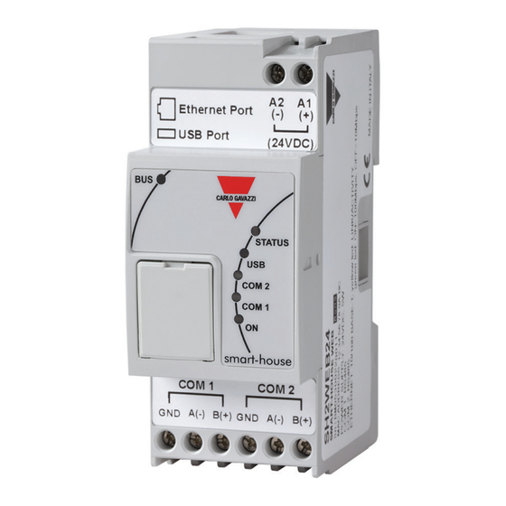
1.1 The master unit: Sx2WEB24 (SH2WEB24 or SB2WEB24) The system is based on a central CPU, the Sx2WEB24, a Linux based embedded PC that manages all the smart functions. It is programmed by means of powerful software, the Sx tool. The Sx2WEB24 has the Ethernet communication capability to be remotely controlled and monitored by smart-devices/PCs;... -
Page 6: Sx2Web24 Bus Description
The SH2UMMF124 is no longer available. RS485 port 1: This is a serial port used to connect to other third party serial devices. RS485 port 2: This is a serial port with modbus master capability used to connect to Carlo Gavazzi energy meters. - Page 7 The buses can be summarized as shown below. N.B.: All the connections described in the following paragraphs must be carried out without power supply. How to install a Sx2WEB system...
-
Page 8: Bus Generators
1.2 Bus generators The Sx2WEB24 (i.e. SH2WEB24 or SB2WEB24) is the brain of the smart-house system but it cannot work alone and it needs the Dupline® bus generators to send commands to the slave modules and collect information from them. For this reason, the Dupline® bus generators can be considered as the pulsating heart that makes all the information flow. - Page 9 Example 2: The bus generators are mounted in different cabinets. How to install a Sx2WEB system...
-
Page 10: Wiring The High Speed Bus
Example 3: The bus generators SH2MCG24 do not need to be put all together in a DIN rail, and they can be mixed with the Dupline® modules as is shown in the picture below. Sx2WEB24 SH2MCG24 SH2RE16A4 SH2RE16A4 SH2MCG24 SH2INDI424 SH2INDI424 SH2MCG24 HSBUS Also in this case there is no need to wire the RS485 for the HS speed bus since the local bus connector... -
Page 11: The Dupline® Bus
1.2.2 The Dupline® bus The Dupline® bus is a signal transmission system that reduces the need for wires, as compared to an ordinary installation. Using only 2 wires, the information can be transmitted from up to 2 km away. Many input and output modules are supplied from the same 2 wires. - Page 12 The so-called decentralised modules can be divided into the following groups: Light switches PIR sensors Temperature displays Water and smoke detectors Wind sensors Humidity sensors Light sensors Decentralised input/output modules The installation is not to be engineered around the Dupline® bus because it can be matched to the application.
-
Page 13: Cable And Installation Tips
1.2.3 Cable and installation tips 1.2.3.1 New Installation Planning When planning a new installation, a generic Bus cable can be used: it is better to use a twisted cable in order to prevent electrical noise from affecting one conductor more than the other and thereby creating an unbalanced Dupline®... - Page 14 1.2.3.2 Installation on Existing Cables If the installation uses existing cables, it is important to verify the cross section of conductors according to the above cable section table. Once the cable size is checked, it is important to ensure that there is no leakage between the two conductors and, also, no leakage from the conductors to ground or shield.
- Page 15 Connection examples: Wrong connection: Cabinet 4 Cabinet 5 Dupline modules Dupline modules (e.g. 6 SH2RE16A4) (e.g. 4 SH2RE16A4) 150 m Cabinet 2 Dupline modules (e.g. 6 SH2RE16A4) 150 m Cabinet 3 Dupline modules (e.g. 6 SH2RE16A4 Main Cabinet Sx2WEB24+SH2MCG24 This network design is not recommended because the cable resistance and the load from bus-powered modules result in an excess of voltage drop.
- Page 16 Right connection: Cabinet 4 Cabinet 5 Network 2 SH2MCG24 Dupline modules Red and Violet Cabinets + Dupline modules (e.g. 6 SH2RE16A4) (e.g. 4 SH2RE16A4) 150 m Network 1 Orange and green Cabinets Cabinet 2 Dupline modules (e.g. 6 SH2RE16A4) 150 m Cabinet 3 Dupline modules (e.g.
-
Page 17: How To Extend The Dupline ® Bus
1.2.4 How to extend the Dupline ® bus 1.2.4.1 Network design Sometimes, in new or in existing installations, there is the need to extend the length of the Dupline® network beyond the typical Dupline® operative distance. At the same time, it could be necessary to place some modules at the end of the Dupline®... - Page 18 1.2.4.2 Repeater wiring The repeater regenerates the voltage level of the Dupline® signal from the bus generator and also provides an output drive capability of up to 300mA. Since most of the Dupline slave modules are bus- powered, the SB2REP230 provides the bus power supply to the modules connected to it. Example 1 Sx2WEB24 SH2MCG24...
- Page 19 The Dupline® repeater does not create any new Dupline® network: all the Dupline® slave modules connected to the SB2REP230 are part of the same network generated by the SH2MCG24 which the repeater is connected to. Example 2 The example below shows the network topology Network Network Module...
- Page 20 1.2.4.3 Isolator feature In addition, the isolator feature contributes to the separation of the sides of the bus for maximum safety. The primary and secondary Dupline® signals are isolated, which means the primary side, made up of the modules connected to the Dupline® generator, will continue to operate in the case of a short circuit on the secondary side, made up of the modules connected to the Dupline®...
- Page 21 Example of correct wiring: The example below shows a correct network design, where the installer has placed the Dupline® DIN- rail modules in different cabinets and the distances have been calculated by considering the cable section and the voltage drop due to the bus-powered connected modules. Cabinet 3 Cabinet 4 Smart Dupline modules...
- Page 22 How to install a Sx2WEB system...
-
Page 23: How To Define The Number Of Dupline® Networks
1.2.5 How to define the number of Dupline® networks The smart-house system is based on a new protocol over the Dupline® bus that is called SmartDupline®. Smart Dupline® implements a master-slave protocol running over standard Dupline® networks. The concept of SmartDupline® is based on the SIN: it is a Specific Identification Number that is unique for each Dupline®... - Page 24 The consumption of input/output signals and current of every slave Dupline® module is given in the relevant datasheet. Current consumption: in the datasheet/instruction manual this is always given in the Dupline® Specifications of each module. Dupline® channel consumption: in the datasheet/instruction manual this is always given in the Mode of Operation section under Coding/Addressing.
-
Page 25: Dupline® Bus In The Cabinet
1.2.6 Dupline® bus in the cabinet Thanks to the local bus concept, the DIN-rail slave modules (dimmers, relays, rollerblind modules, etc…) can just be plugged into the SH2MCG24, without the need for any wiring. The decentralised modules, such as light switches, PIR sensors, temperature display, …are connected to the SH2MCG24 by the two wires coming from the terminals at the top. - Page 26 Example 2: Network Network Network Module Module Module Module SX2WEB24 SH2MCG24 SH2RE16A4 SH2RE16A4 SH2MCG24 SH2SSTRI424 SH2MCG24 SH2SSTRI424 Modules A and B are connected to the Dupline® network 1. Module C is connected to the Dupline® network 2. Module D is connected to the Dupline® network 3. Since there are no Dupline®...
- Page 27 Example 3: How to install a Sx2WEB system...
-
Page 28: The Wireless Bus Widup
Recommendations: Do not connect one SH1DUPFT to two Dupline® networks, otherwise the two buses will be short-circuited: the situation below must be avoided. This connection must be avoided otherwise two Dupline® networks will be short circuited. If this should happen, the system will not be damaged since the bus is protected, but it will not work properly. -
Page 29: How To Connect The Modem
1.4 How to connect the modem The Universal Mobile Modem SH2UMMF124 or the USB Dongle Connection Module SH2DSP24 have to be connected to the Sx2WEB24 through the auxiliary bus on the left side of the Sx2WEB24. The modem can be used to send/receive messages or to access the Internet when the LAN connection is not available. - Page 30 The table below shows the compatible USB modems: Manufacturer Model Type HUAWEI MS2131 3G modem D-LINK DWM 157 Recommendation: Place the modem where there is good signal reception: this can be checked by connecting to the Sx tool: at the bottom of the user interface there are 5 bars that indicate the field strength, as shown in the picture below.
-
Page 31: How To Connect The Universal Mobile Modem Sh2Ummf124
1.4.2 How to connect the Universal Mobile Modem SH2UMMF124 The Universal mobile modem SH2UMMF124 module is no longer available: it is mentioned here only to understand compatibility with the past. The installer has to perform the following steps to install the SH2UMMF124 modem: 1. -
Page 32: How To Connect The Energy Meters
1.5 How to connect the energy meters COM port 2 of the Sx2WEB24 is an RS-485 port with Modbus master capability. COM port 1 can be configured as Modbus master or Modbus slave. The Sx2WEB24 is a data logger that collects data from the energy meters. Up to 128 energy meters can be connected to one Sx2WEB24: ... -
Page 33: Ethernet Connection
1.6 Ethernet connection The Sx2WEB24 is configured by using the Sx tool, which has to be connected via the LAN port on the top of the Sx2WEB24. When connecting the network cable, the Ethernet port LEDS will also light up. To configure the IP address, please refer to the Sx tool software manual. -
Page 34: Micro Sd
1.7 Micro SD The IP address can be changed by using a “Micro SD” or “SDHC” memory card correctly inserted into the relevant slot (see Sx tool software manual). N.B: the maximum capacity of the Micro SD card is 16GB. 1. -
Page 35: Pen Drive Installation
1.8 Pen drive installation The IP address can be changed by using a Pen drive. N.B: the maximum capacity of the Micro SD card is 16GB. 1. Identify the USB port specifically designed for the insertion of the “Pen Drive” memory. 2. -
Page 36: Sizing Of Carlo Gavazzi Dc Power Supply
1.9 Sizing of Carlo Gavazzi DC power supply The smart-house system is powered by 24 Vdc nominal (15-30 Vdc) Since most of the Decentral Dupline® slave modules are powered by the bus, the sizing of the power supply has to be based on the DIN-rail modules, and among these only the ones powered by 15 to 30 Vdc: the power dimmers and the relay output modules that switch 230 Ac load are powered by 230Vac. -
Page 37: How To Wire The Power Supply
1.9.2 How to wire the power supply The DIN-rail modules powered by to 24 Vdc nominal (15-30 Vdc) come with in/out connections to speed up wiring: there are two A1(+) terminals that are internally short circuited, and two A2(-) terminals that are also short circuited. -
Page 38: Installing The Smart-House System
2. Define the number of necessary bus generators, following the suggestion described in paragraph How to define the number of Dupline® networks 3. Size the 24 Vdc power supply as described in paragraph Sizing of Carlo Gavazzi DC power supply 4. -
Page 39: Appendix "A" - Rs485 Network Guidelines
3 Appendix “A” – RS485 network guidelines 3.1 MODBUS via Serial line (RS-485) guidelines 3.1.1 Introduction The RS-485 is a half-duplex multidrop network: multiple transmitters and receivers may share the same line, but only one transmitter may be active at any given time. The TIA/EIA-485-A says nothing about the communication protocol to be used. -
Page 40: Rs-485 Topology
3.1.7 RS-485 topology Due to signal reflection issues, topology is not free, but only certain configurations are allowed. The only configuration which guarantees sufficient reliability is the daisy-chain. The maximum length of a derivation is 1 metre. How to install a Sx2WEB system... -
Page 41: Appendix B - Safety Recommendations
4 Appendix B - Safety recommendations This section contains important safety related information. If these recommendations are not strictly followed, serious damage may occur to devices or machinery and serious injury or death may occur to people. Please read this manual carefully before beginning any installation, maintenance or operational activity. - Page 42 The manufacturer denies any kind of direct or SAFETY RECOMMENDATIONS indirect responsibility for consequences resulting from non-observance safety recommendations from misuse equipment. ELECTRICAL COMPONENTS CONSTANTLY UNDER HIGH VOLTAGE Carefully check wiring. Incorrect wiring of the device terminals can cause irreversible damage to DANGER !!! the equipment and injury to operators.
Need help?
Do you have a question about the Sx2WEB Series and is the answer not in the manual?
Questions and answers