
Related Manuals for Simpro Multi-Tip 1600


Summary of Contents for Simpro Multi-Tip 1600
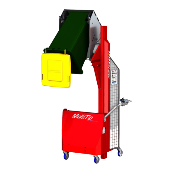
- Page 1 SERVICE MANUAL Simpro Multi-Tip © Simpro Handling Equipment Ltd | v40.0 | June 2018...
- Page 3 Copyright ©2018 Simpro Handling Equipment Limited. All rights reserved. No part of this publication may be copied or distributed in any form without permission from the copyright holder. Service Manual | Simpro Multi-Tip | v40.0 | June 2018 | Page 2...
-
Page 4: Table Of Contents
Contents 1 General Overview ......................... 5 2 Layout of Parts ..........................6 3 Troubleshooting Guide ......................... 7 4 Electrical System ........................... 8 4.1 General Description ........................8 4.2 Wiring and Circuit Diagrams ...................... 8 4.3 Battery ............................9 Removal and Refitting ....................9 Testing ........................ - Page 5 Removal and Refitting .................... 22 8.5 Tipping Guide Gate Flap ......................23 8.6 Tipping Guide Frame .......................23 Adjustment ......................23 8.7 Castor Wheels .........................23 9 Spare Parts Guide ........................24 Service Manual | Simpro Multi-Tip | v40.0 | June 2018 | Page 4...
-
Page 6: General Overview
1 General Overview The lifting power for Multi-Tip tippers comes from a hydraulic power pack, normally battery- powered but may be mains-powered (refer to separate booklet for service of mains-powered machines). When the “Raise” button is pressed, the motor runs and hydraulic oil is forced under pressure into the lift ram, causing it to extend. -
Page 7: Layout Of Parts
2 Layout of Parts Service Manual | Simpro Multi-Tip | v40.0 | June 2018 | Page 6... -
Page 8: Troubleshooting Guide
Lack of lubrication be able to move freely. Lubricate with a silicon spray or dry lubricant. Do not use grease or oil. Gas strut bent or Contact Simpro to arrange replacement. damaged Lifting chain rusty or The cradle won't Refer to section 8.4... -
Page 9: Electrical System
The Control switches are rated to IP 66 and the motor is IP55. Always keep the charging socket dry. If it gets wet, it should be dried before the lead is plugged in. 4.2 Wiring and Circuit Diagrams Service Manual | Simpro Multi-Tip | v40.0 | June 2018 | Page 8... -
Page 10: Battery
4.3 Battery Battery-powered machines normally have a sealed 21 amp-hour gel battery mounted on a bracket at the right-hand side of the main box. Depending on the amount of usage, the battery should have a life of 2 - 3 years; if used continuously or not maintained correctly, the life may be reduced. A battery with larger capacity can be fitted if required. -
Page 11: Battery Isolator
To replace, slide a new charger in, and bend the tab back up to retain it. Connect the wiring plug and socket. Powerpack enclosure • Battery charger is visible at top right. • Charger is secured by two folding tabs. Service Manual | Simpro Multi-Tip | v40.0 | June 2018 | Page 10... -
Page 12: Motor Relay
4.6 Motor Relay Testing Remove the box cover panel. The relay is mounted on top of the motor. The relay should ‘click’ when the “Raise” and “Safety” switches are pressed. If there is no click, check that there is a positive signal on the blue wire when the Raise and Safety buttons are pressed, and that the black wire has a negative connection. -
Page 13: Lowering Valve Solenoid
Replace the correct way around, refit the O-ring and nut. The nut must be tightened finger-tight only. Lowering Valve Solenoid • When open, this electromagnetic valve allows oil to flow back into the reservoir, lowering the cradle Service Manual | Simpro Multi-Tip | v40.0 | June 2018 | Page 12... -
Page 14: Control Switches
4.8 Control Switches Removal and Refitting Remove the screws holding the top cover of the handle controls. The coupling plate and contact blocks can be removed from the switch by turning the release plate. III. The individual contact blocks can also be removed if necessary, by unclipping from the coupling plate. -
Page 15: Hydraulic Powerpack
Loosen the screws holding the outer cover and remove it. III. Make note of the wiring connections to the motor and disconnect. Undo the retainer nut holding the lowering solenoid coil on and remove it. Service Manual | Simpro Multi-Tip | v40.0 | June 2018 | Page 14... -
Page 16: Lowering Valve
Undo the swivel fitting holding the hydraulic hose to the power pack. Plug or tape the fittings to prevent ingress of dirt. Undo the 2 bolts or screws holding the power pack mount bracket and lift it away. Refitting is a reversal of the above procedure, with attention to the following points: Ensure the wiring is reconnected the same as original. -
Page 17: Adjustment
It very rarely fails, but if some foreign matter gets in, it may not seal properly, allowing the cradle to come down when the Raise button is released. A special tool is needed to extract the check valve. Please contact Simpro if you think it may need to be removed. -
Page 18: Hydraulic Ram
If there is a pinhole leak in a weld, it is generally best to fit a complete replacement ram body, and return the faulty one to Simpro for repair. If this is not feasible, mark the location of the hole, and grind a groove at least 3mm deep, and 10mm each side of the... -
Page 19: Hose-Burst Valve (If Fitted)
The hose-burst valve operates if the flow out of the ram exceeds approx. 10 litres/min. If it does lock, the hose must be repaired, then the ram extended slightly before it will reset. The valve cartridge may be unscrewed from the port with a special tool available from Simpro. 6.5 Ram-end Roller Replacement Lower the cradle to the ground, then remove the upper and lower ram covers. -
Page 20: Bin Cradle
7 Bin Cradle 7.1 General Description The standard cradle is designed to hold all common 2-wheeled bins up to 240 litres. A range of catch kits can be bolted on to enable it to hold 205-litre steel and plastic drums, Brute bins, and other similar drums. -
Page 21: Cradle Jamming
Check the position of the shaft collar on the end of the main shaft. The follower roller at the top of the cradle should be held firmly against the guide, but not so tight that it causes the cradle to jam. Service Manual | Simpro Multi-Tip | v40.0 | June 2018 | Page 20... -
Page 22: General
8 General 8.1 Cradle Carrier The Cradle Carrier is a fabricated steel frame with four plastic ‘mast blocks’. The lifting chain hooks onto a bracket at the bottom, and the cradle axle bolts onto it. It also has a gas strut mounted at the top, which helps to ensure the cradle does not stick at the top. -
Page 23: Mast Blocks
Disconnect the chain from the bracket at the bottom of the cradle carrier. Re-connect the new chain, and tap the bracket with a hammer to ensure that the chain is retained tightly. Reassembly is a reversal of this process. Service Manual | Simpro Multi-Tip | v40.0 | June 2018 | Page 22... -
Page 24: Tipping Guide Gate Flap
8.5 Tipping Guide Gate Flap A gate flap is used to ‘switch’ the follower roller during the lifting and lowering cycle. The flap must move freely without sticking. A pin welded to the cradle lifts the flap when the cradle is approximately horizontal while lowering. -
Page 25: Spare Parts Guide
9 Spare Parts Guide The following table above includes only the most common parts. A full list of parts is available on request from Simpro, or may be viewed on our support site http://support.simpro.world Part Number Description 0230040001 Tip guide flap... - Page 26 Multi-Tip 1600, Stainless Steel. Many other options available. http://simpro.world/multi-tip...
Need help?
Do you have a question about the Multi-Tip 1600 and is the answer not in the manual?
Questions and answers