Table of Contents
Advertisement
Quick Links
Advertisement
Table of Contents

Subscribe to Our Youtube Channel
Related Manuals for Extech Instruments EX542


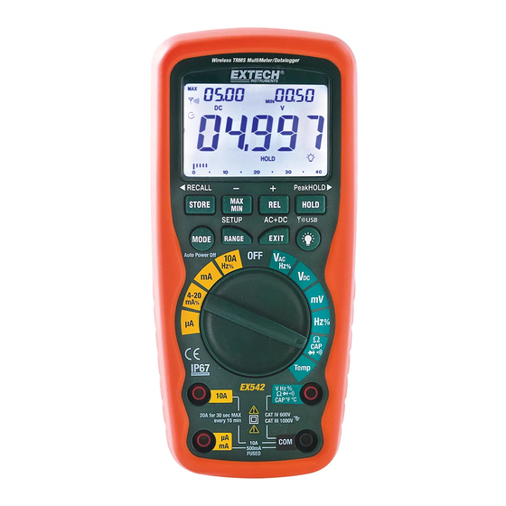
Summary of Contents for Extech Instruments EX542
- Page 1 User's Guide Wireless TRMS Multimeter Model EX542...
- Page 2 Note – Examples include switches in the fixed installation and some equipment for industrial use with permanent connection to the fixed installation. OVERVOLTAGE CATEGORY IV Equipment of OVERVOLTAGE CATEGORY IV is for use at the origin of the installation. Note – Examples include electricity meters and primary over-current protection equipment EX542-en-GB_v1.5 06/15...
-
Page 3: Safety Instructions
NEVER operate the meter unless the back cover and the battery and fuse covers are in place and fastened securely. If the equipment is used in a manner not specified by the manufacturer, the protection provided by the equipment may be impaired. EX542-en-GB_v1.5 06/15... -
Page 4: Symbols And Annunciators
Direct current HOLD Display hold ºF Degrees Fahrenheit ºC Degrees Centigrade Maximum Minimum Serial number second Set up parameter AC +DC Alternating current + Direct current TRMS Ture RMS Store Recall AUTO Auto Range Auto Power off enabled Backlight EX542-en-GB_v1.5 06/15... -
Page 5: Dc Voltage Measurements
Read the frequency in the main display. Press the MODE button again to indicate “%”. Read the % of duty cycle in the main display. With ACV in the main display, press EXIT for 2 seconds to measure AC+DC. EX542-en-GB_v1.5 06/15... -
Page 6: Mv Voltage Measurements
Touch the black test probe tip to the negative side of the circuit. Touch the red test probe tip to the positive side of the circuit. Apply power to the circuit. Read the current in the display. EX542-en-GB_v1.5 06/15... -
Page 7: Ac Current (Frequency, Duty Cycle) Measurements
Touch the test probe tips across the circuit or part under test. It is best to disconnect one side of the part under test so the rest of the circuit will not interfere with the resistance reading. Read the resistance in the display. EX542-en-GB_v1.5 06/15... -
Page 8: Continuity Check
Insert the black test lead banana plug into the negative COM jack. Insert the red test lead banana plug into the positive V jack. Press the MODE button to indicate “F” Touch the test leads to the capacitor to be tested. Read the capacitance value in the display EX542-en-GB_v1.5 06/15... -
Page 9: Temperature Measurements
Insert the black lead banana plug into the negative COM jack and the red test lead banana plug into the positive Hz jack. Touch the test probe tips to the circuit under test. Read the frequency on the display. Press the MODE button to indicate “%”. Read the % duty cycle in the display. EX542-en-GB_v1.5 06/15... -
Page 10: Autoranging/Manual Range Selection
Press the REL button to store the reading in the display and the "▲" indicator will appear on the display. The Right auxiliary display displays the initial reading (the stored value) The Left auxiliary display displays the actual currently measured value. Main display displays the Relative value (currently measured value minus the stored value). EX542-en-GB_v1.5 06/15... -
Page 11: Display Backlight
To clear the memory of all stored data, from the OFF position, hold the EXIT button and switch the function switch to any position. Release the EXIT button and the LCD will flash 3 times and a buzzer will beep three times. Memory is now clear. EX542-en-GB_v1.5 06/15... -
Page 12: Low Battery Indication
AC+DC testing. The precision is the same as in the AC measure modes. The LCD shows AC+DC icon. Press the EXIT button to exit the mode. LOW BATTERY INDICATION When the icon appears in the display, the battery should be replaced EX542-en-GB_v1.5 06/15... -
Page 13: Maintenance
You can hand over your used batteries / accumulators at collection points in your community or wherever batteries / accumulators are sold! Disposal: Follow the valid legal stipulations in respect of the disposal of the device at the end of its lifecycle EX542-en-GB_v1.5 06/15... -
Page 14: Replacing The Fuses
70-172-40], 10A/1000V fast blow for the 20A range [SIBA 50-199-06]). 7. Replace and secure the rear cover, battery and battery cover. WARNING: To avoid electric shock, do not operate your meter until the fuse cover is in place and fastened securely. EX542-en-GB_v1.5 06/15... -
Page 15: Specifications
(20A: 30 sec max with reduced accuracy) All AC voltage ranges are specified from 5% of range to 100% of range NOTE: Accuracy is stated at 18 C to 28 C (65 F to 83 F) and less than 75% RH. EX542-en-GB_v1.5 06/15... - Page 16 ±50 digits 0mA=-25%, 4mA=0%, 20mA=100%, 24mA=125% Note: Accuracy specifications consist of two elements: (% reading) – This is the accuracy of the measurement circuit. (+ digits) – This is the accuracy of the analog to digital converter. EX542-en-GB_v1.5 06/15...
- Page 17 EN61010-1 and IEC61010-1 2 Edition (2001) to Category IV 600V and Category III 1000V; Pollution Degree 2. The meter also meets UL 61010-1, 2 Edition (2004), and CAN/CSA C22.2 No. 61010-1 2 Edition (2004) Copyright © 2013‐2015 FLIR Systems, Inc. All rights reserved including the right of reproduction in whole or in part in any form ISO‐9001 Certified www.extech.com EX542-en-GB_v1.5 06/15...
Need help?
Do you have a question about the EX542 and is the answer not in the manual?
Questions and answers