Advertisement
Quick Links
Warning
CHOKING HAZARD - Small parts. This product contains choking hazards and is not suitable for children under the age of 3.
WARNING
Make sure to read these instructions carefully before assembly or use of these materials.
(Parents/Guardians: be sure to read the instructions and ensure children read them as well.)
● These materials are not designed for children under 8 years of age. Children under 8 should
only use these materials with adult supervision.
● Please see any manual or textbook included with the product for instructions on safe
assembly and use. Make sure to follow cable connection instructions to avoid damage or
injury from incorrect assembly.
● This product is not edible. Do not put any parts of this product into your mouth to prevent
accidental ingestion.
● Do not wrap cords or cables around your hands, fingers, neck, etc. Do not plug any cables
into household outlets, or you may receive an electric shock.
● To avoid injury, do not touch the rotating parts of the motors when the power is turned on.
● Should the Core Unit, motor or Battery Box become very hot, immediately turn off the
power and cease handling the device.
● Be aware that using the motor or Core Unit under certain conditions (improper handling,
excessive load, extreme temperatures) may cause it to overheat, and take care to avoid burns.
● Be sure that the motion of the included DC Motor's axle is not obstructed when the motor
is powered. Even brief obstruction may cause burning depending on the condition of the
motor.
● Some parts have sharp edges, so handle with care.
● Do not leave parts lying on the floor, as they may cause injury if stepped on.
1
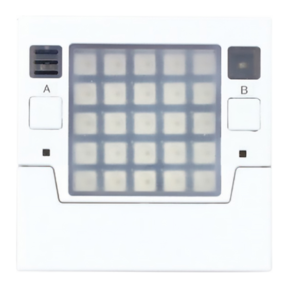
Parts of the Core Unit
The Core Unit is the part of the robot that runs programs.
(Front)
⑤
①
②
④
⑧
① Temperature Sensor
This sensor measures external temperature. ★ The internal temperature of the Core
Unit may affect the readings of the temperature sensor if it becomes heated by extend-
ed use of significant electrical power, for instance using the LED matrix.
②/③ A/B Buttons
The Core Unit detects when these buttons are pressed.
④ Power Light (Green)
This light turns on when the power is on.
⑤ 5 x 5 Full Color LED Matrix
These LEDs light up in RGB colors to display various images.
⑥ Light Sensor
This sensor uses a photo transistor that converts light into
electricity to measure the intensity of surrounding light.
⑦ Connection Light (Blue)
This light turns on when wireless communications
(through Bluetooth/Wi-Fi) are occurring.
⑧ Artec Block Connecting Cover
This cover can be attached to the edge connector.
It has studs on it that can be used to connect to Artec Blocks.
⑨ Buzzer
Transforms electrical signals into sound.
ArtecRobo
(Back)
⑥
③
⑦
⑩
● Be careful not to get fingers pinched between movable parts.
● Do not subject the product to strong impacts, set heavy objects on top of it, etc.
● For your safety, avoid using parts that have been damaged.
● When not in use, shut off all power to the product and store out of reach of small
children.
Improper battery usage may result in overheating, rupture, or leakage, so take note of the
following when using batteries:
● Do not use non-alkaline batteries. Rechargeable batteries in particular are known to
cause problems, so do not use them.
● Batteries are to be inserted with correct polarity.
● Do not mix old and new or different kinds of batteries.
● Do not attempt to short circuit, recharge, disassemble, or heat batteries. Do not insert
batteries into fire.
● If it will be out of use for an extended period of time, remove the batteries from the
battery box.
● If battery leakage occurs and any battery fluid gets into the eyes, immediately flush with
water and seek medical treatment. If fluid comes into contact with skin or clothes, wash
immediately with water.
⑨
⑩ 9-Axis Sensor
・ 3-Axis Accelerometer: Quantifies the device's motion and tilt
by measuring acceleration.
・ 3-Axis Gyroscope: Measures angular velocity to quantify
rotational motions the accelerometer can't detect.
・ 3-Axis Compass: Quantifies which way the device is facing by
measuring the Earth's magnetic field.
⑪ Edge Connector
A connector for external expansion devices.
⑫ USB Port (microB)
A port used to plug USB cables into the device to transfer
programs from a computer or supply power.
⑬ Reset Button
This button is used to restart the device.
⑭ Power Connector
A port used to plug a Battery Box into the device to supply
power.
Instructions
⑪
(Top)
⑫
⑬
⑭
1
Advertisement

Subscribe to Our Youtube Channel
Related Manuals for Artec Robo 2.0


Summary of Contents for Artec Robo 2.0
- Page 1 ・ 3-Axis Accelerometer: Quantifies the device's motion and tilt ④ Power Light (Green) by measuring acceleration. ・ 3-Axis Gyroscope: Measures angular velocity to quantify This light turns on when the power is on. rotational motions the accelerometer can't detect. ⑤ 5 x 5 Full Color LED Matrix ・ 3-Axis Compass: Quantifies which way the device is facing by These LEDs light up in RGB colors to display various images. measuring the Earth's magnetic field. ⑥ Light Sensor ⑪ Edge Connector This sensor uses a photo transistor that converts light into A connector for external expansion devices. electricity to measure the intensity of surrounding light. ⑫ USB Port (microB) ⑦ Connection Light (Blue) A port used to plug USB cables into the device to transfer This light turns on when wireless communications programs from a computer or supply power. (through Bluetooth/Wi-Fi) are occurring. ⑬ Reset Button ⑧ Artec Block Connecting Cover This button is used to restart the device. This cover can be attached to the edge connector. It has studs on it that can be used to connect to Artec Blocks. ⑭ Power Connector ⑨ Buzzer A port used to plug a Battery Box into the device to supply power. Transforms electrical signals into sound.
- Page 2 ⑪ Functions of Each Edge Connector Pin Core Unit Digital I/O Analog Communications Digital I/O I2C SDA Digital I/O I2C SCL +3v3 +3v3 +3v3 Digital I/O Digital I/O SPI MOSI Digital I/O SPI MISO Digital I/O SPI SCK Analog IN LED Matrix data Digital I/O button B Digital I/O Digital I/O UART TXD Digital I/O UART RXD Digital I/O Analog IN ICM20948-INT Digital I/O Digital I/O button A Buzzer Digital I/O Digital I/O Analog IN Analog IN ● Core Unit Specifications 60 x 60 x 25 mm (in case) Size microB...
- Page 3 Using the Battery Box The Battery Box plugs into the power connector (marked BATT) on the Core Unit. To power a DC Motor or Servomotor, power must be supplied via the power connector on the Robot Expansion Unit (see page 7). ● Uses three AA batteries. ● Batteries must be inserted with the correct polarity. ● Remove the batteries if the device will be out of use for an extended period of time. Starting the Core Unit ① Connect the power (standard start-up) (1) Plug the Battery Box or a USB cable into the Core Unit. (2) The power will automatically switch ON and the green power light will illuminate. ② Go to Program Select Mode Reset Button (1) Hold down A and press the reset button. Pressing the reset button will restart the device, so the power light will turn off briefly. (2) If the power light turns back on 3 seconds after you release A Button the reset button, then release the A button. (3) If the display shows a 0 in green LEDs, you have entered Program Select Mode. ③ Program Selection/Start-Up (1) Pressing the A button when in Program Select Mode will change the displayed number (0, 1, 2, etc.). The number can go up to 9 before returning to 0. (2) Pressing the B button when a number is displayed will run the program that has been assigned to that number. ★ On first start-up, the device will contain sample programs for testing purposes. Please test this functionality before you begin programming the device yourself. (See pages 4-5 for information on the sample programs.) ★ Downloading a new program from the software to one of the program slots will overwrite the sample program in that slot.
- Page 4 ④ Turn off the power Disconnect the Battery Box and/or USB cable from the Core Unit. The next time you conduct a standard start-up (as in ①) the program you selected in ③ will run.
- Page 5 Running the Sample Programs This section describes the sample programs the device can run in its initial state on first start-up. The following programs are included: Program Effects No program assigned. Adjustable Light All the display LEDs turn on. Pressing the A button will adjust the brightness of the lights, and pressing the B button will change their color. Night Light Covering the light sensor to create darkness will make the LEDs light up. Thermometer The current temperature will scroll across the display. Rolling Light The accelerometer will make the position of the light on the display move as you tilt the device.
- Page 6 Program Effects Turntable Spin the device around to reverse or change the speed of the song it's playing. The compass will make the Compass device display an arrow pointing north. ★ This requires the compass to be calibrated after device start-up. To calibrate, rotate the Core Unit until all the LEDs on the outer border of the display are illuminated. The buzzer will produce Current Tester different sounds depending on the electrical resistance between points GND and 0-2 on the edge connector. Grasp point 0, 1, or 2 along with GND to make a measurement. Light Game Press the A and B buttons to move a green light left and right and avoid the red lights falling from above. Wi-Fi Connection Checker The current MAC address will scroll across the display. You can confirm the Wi-Fi connection is working with the MAC address displayed on a tablet or other device's Wi-Fi selection screen.
- Page 7 5 Using Artec Blocks ● Artec Block's special shape means you'll have to keep the position of the studs in mind as you build. Read along with the Instruction Manuals to see where the studs should be. Studs ● Remove Artec Blocks from one another by pulling them straight apart. Forcing the blocks to bend may break them. Pull apart in the direction of the arrow Damage ● If you have trouble separating blocks with your hands, try using the Block Remover. So you're having trouble taking apart your blocks... And if you're still having trouble... Use your Use your ① Pl a ce t h e u p p e r p a r t of t h e re m ove r Block Remover! Block Remover! (shown by A) into the gap between the blocks. ① Use the claws to pinch the base of ② Slide the remover and pull. the block. You'll hear a pop as a ...
- Page 8 P0 P1 ⑥ I2C Communication Terminal A terminal where sensors that use I2C buses ② (Accelerometers) can be connected. ●Using Connectors ● Note on Using Separately Packaged Artec Robo Parts All of the ports in this unit are polarized. Original Artec Robo parts can All connectors used in Artec Robo 2.0 Artec Artec be connected to the unit, but have nonreversible plugs. Robo Robo 2.0 the connecting cables for Make sure the plug is facing the right way plug plug sensors and Servomotors do when you connect it. not have nonreversible plugs. Make sure to connect them so that the colors of the wires line up with the matching □ marks above the port, as shown to the left. ★ Artec Robo's 4-wire sensor connecting cable (for Accelerometers) is not compatible with this unit.
- Page 9 7 Parts Compatible with the Robot Expansion Unit ● LEDs LEDs come in four colors: white, blue, green, and red. They can be distinguished from one another by the writing on their circuit boards. They can be connected to the Robot Expansion Unit's 3-wire digital output terminals (P13/P14/P15/P16) with a 3-wire sensor connecting cable. Green White Blue ● Buzzers Buzzers can transform electric signals into sound. Buzzers are easy to confuse with IR Photoreflectors based on their appearance, so pay attention to the writing on the circuit board that labels the part. They can be connected to the Robot Expansion Unit's digital output terminals (P13/P14/P15/P16) with a 3-wire sensor connecting cable. Check the label The device can control up to four Buzzers at one time, and you'll see including the internal buzzer in the Core Unit. Buzzer written there ● Servomotors 90° Direction of Rotation Servomotors are motors that turn to precisely specified angles. They can be connected to the Robot Expansion Unit's digital output terminals (P13/P14/P15/P16). 180° 0° The default angle of a servomotor is 90° , and it can move left and right from 0-180° . The rotational direction of your Servomotor is printed in the location shown on the Default Position right.
- Page 10 ● DC Motors The speed and duration of a DC Motor's rotation can be changed by adjusting the amount of and length of time that electricity runs through it. Multiple internal gears transfer the rotations of the motor to the axis. They can be connected to the Robot Expansion Unit's DC Motor terminals (M1/M2). DC Motors require power from an external power supply even when your device is receiving power from a connected USB cable. DC Motor Slip To prevent damage to the internal gears, the motor is designed to emit clicks and begin turning freely ("slip") when excessive strain is placed on the axis. Should this occur, you will need to inspect the motor and fix any strain being placed on the gears. The wear and tear caused by continuously running a motor in this condition reduces the amount of strain required for another slip to occur. ● Touch Sensors A Touch Sensor is a physical sensor with a button on one end. The Touch Sensor reads as ON when the button is pressed and OFF when it is not. They can be connected to the Robot Expansion Unit's analog input terminals (P0/P1/P2) with a 3-wire sensor connecting cable. ● Sound Sensors Sound Sensors have a black sponge on the front end and use a condenser microphone to pick up sound: the louder the sound, the higher the value from the sensor. They can be connected to the Robot Expansion Unit's analog input terminals (P0/P1/P2) with a 3-wire sensor connecting cable. ● Light Sensors Light Sensors use an electronic device called a phototransistor that converts light into electricity to measure the intensity of surrounding light. The brighter the light, the higher the value from the sensor. Light Sensors look similar to LEDs, but you can tell them apart by the color of the circuit board (black) and the label written on them. They can be connected to the Robot Expansion Phototransistor Unit's analog input terminals (P0/P1/P2) with a 3-wire sensor connecting cable. ● Accelerometers Accelerometers convert changes in slope and movement into numerical values. It can be connected to the Robot Expansion ...
- Page 11 Check the label ● IR Photoreflectors and you'll see IR Photoreflectors can be easily confused for Buzzers. You can IR Photoreflector written there tell them apart using the text on their circuit boards. They can be connected to the Robot Expansion Unit's analog input terminals (P0/P1/P2) with a 3-wire sensor connecting cable. A Bit About IR Photoreflectors A Bit About IR Photoreflectors An IR Photoreflector emits invisible infrared light using an LED and detects the amount of light reflected back, converting it to a numeric value: the closer an object is, the higher the value. However, the sensor may not be able to detect objects that are too close. The color of an object can also affect the reflection, which in turn affects the value. ★ Natural light contains detectable infrared light. Depending on your environment, this can affect your sen- sor's values. Infrared Receiver Infrared LED ● Sensor Connecting Cables (3-wire) Used With LEDs, Buzzers, IR Photoreflectors, Touch Sensors, Light Sensors, Sound Sensors ● Sensor Connecting Cables (4-wire) Used With Accelerometers...
-
Page 12: Software Instructions
Software Instructions For instructions on how to use the software, go to the software download page at this URL: https://www.artec-kk.co.jp/artecrobo2/ 082552 K0419...
Need help?
Do you have a question about the Robo 2.0 and is the answer not in the manual?
Questions and answers