Advertisement
Quick Links
Advertisement

Related Manuals for HydroHoist HarborHoist HH-20,000 V-HULL V-FRAME


Summary of Contents for HydroHoist HarborHoist HH-20,000 V-HULL V-FRAME
- Page 1 Rev. 04072020...
- Page 2 If you have questions, contact the Technical Support Team at 1-800-825-3379. ® Lifts must be installed by an approved HydroHoist installer. Failure to comply will result in termina- tion of warranty and could cause injury to the user and damage to the lift and vessel.
- Page 3 PRE-INSTALLATION CONSIDERATIONS Due to its size, the following determinations must be made before installing a HarborHoist: • Location of lift assembly (remote or on-site) • If remote then, method of transport from assembly to launch site • Equipment required to safely build, transport, and launch the lift •...
- Page 4 Chart 1: General Specification Of The Lift Standard V Hull Series *Tank Dimensions Weight Hull Minimum ***Max Beam of # Main # Aux of lift Bunk Lift Width Boat @ Minimum Lift Lifting Size Width Length Depth Tanks Tanks (lbs.) Length Possible Lift Width...
- Page 5 Chart 2: Required Tools 5/16” Socket Wrench / Driver Drill / Impact Driver 7/16 Drill Bit (tin-coated high helix 6” cut length 7/16” Socket Wrench / Driver recommended) 9/16” Deep Socket Wrench / Driver Hammer / Rubber Mallet 3/4” Deep Socket Wrench / Driver Thread Sealant 7/16”...
-
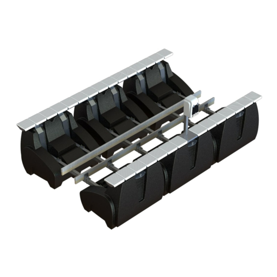
Page 6: Tank Assembly
Chart 4: PARTS LIST—20,000 HH-20,000 V-HULL V-FRAME Part Description Expected Qty TANK ASSEMBLY HH-3000 TANK- HARBORHOIST GEN 1.5 HHE-2650 KIT BOX - HARDWARE - HARBORHOIST TANK SET HH-2601 TOP PLATE - HH GEN 1 MOD- ALUMINUM HH-LPL-1024 GASKET - TOP HARBORHOIST HH-LPL-1028 GASKET - UNDERNEATH - HARBORHOIST HH-7103... - Page 7 Chart 4: PARTS LIST—20,000 Narrow HH-20,000 V-HULL V-FRAME NARROW Part Description Expected Qty TANK ASSEMBLY HH-3000 TANK- HARBORHOIST GEN 1.5 HHE-2650 KIT BOX - HARDWARE - HARBORHOIST TANK SET HH-2601 TOP PLATE - HH GEN 1 MOD- ALUMINUM HH-LPL-1024 GASKET - TOP HARBORHOIST HH-LPL-1028 GASKET - UNDERNEATH - HARBORHOIST HH-7103...
- Page 8 Chart 4: PARTS LIST—20,000 Wide HH-20,000 V-HULL V-FRAME WIDE Part Description Expected Qty TANK ASSEMBLY HH-3000 TANK- HARBORHOIST GEN 1.5 HHE-2650 KIT BOX - HARDWARE - HARBORHOIST TANK SET HH-2601 TOP PLATE - HH GEN 1 MOD- ALUMINUM HH-LPL-1024 GASKET - TOP HARBORHOIST HH-LPL-1028 GASKET - UNDERNEATH - HARBORHOIST HH-7103...
- Page 9 Chart 4: PARTS LIST— 25,000 HH-25,000 V-HULL V-FRAME Part Description Expected Qty TANK ASSEMBLY HH-3000 TANK- HARBORHOIST GEN 1.5 HHE-2650 KIT BOX - HARDWARE - HARBORHOIST TANK SET HH-2601 TOP PLATE - HH GEN 1 MOD- ALUMINUM HH-LPL-1024 GASKET - TOP HARBORHOIST HH-LPL-1028 GASKET - UNDERNEATH - HARBORHOIST HH-7103...
- Page 10 Chart 4: PARTS LIST— 25,000 Wide HH-25,000 V-HULL V-FRAME WIDE Part Description Expected Qty TANK ASSEMBLY HH-3000 TANK- HARBORHOIST GEN 1.5 HHE-2650 KIT BOX - HARDWARE - HARBORHOIST TANK SET HH-2601 TOP PLATE - HH GEN 1 MOD- ALUMINUM HH-LPL-1024 GASKET - TOP HARBORHOIST HH-LPL-1028 GASKET - UNDERNEATH - HARBORHOIST...
- Page 11 STEP 1: WALKWAY TOP PLATE ASSEMBLY Part # Parts Required (Per Tank) Part # Hardware Required Top Plate Nyloc Nut (1/4-20 SS) HH-LPL-1502 HH-2601 Hex Bolt (1/4-20 x 1.5 SS) HH-LPL-1501 Top Gasket HH-LPL-1024 2090216 Flat Washer (1/4” SS) Lock Washer 1/2” 18-8 SS HH-1916 HH-1926 Hex Nut 1/2-13 Brass...
- Page 12 STEP 2: ATTACH TOP PLATE ASSEMBLY TO STRAP PLATES Part # Parts Required (Per Tank) Part # Hardware Required Walkway Assembly HH-LPL-1503 U-Bolt 3/8-16 x 3 x 6 2090242 Flat Washer 3/8” HH-LPL-1025 Strap Plate HH-LPL-1505 Lock Washer 3/8” HH-2603 Brass Nut 3/8-16 Use Kit Box: #HHE-2650 1.
- Page 13 STEP 3: ATTACH TANK FRAME BRACKETS TO STRAP PLATES Part # Hardware Required Part # Parts Required (Per Tank) U-Bolt (3/8-16 x 3 x 5) HH-LPL-1503 Support Channel HH-7102 Flat Head Bolt (5” SS) HH-LPL-1006 Bottom Gasket HH-7103 Nylon HH Tank Bushing HH-LPL-1031 Strap Plate HH-LPL-1025...
- Page 14 STEP 4: ATTACH STRAP PLATE ASSEMBLY TO TANK Part # Hardware Required Part # Parts Required (Per Tank) HH-LPL-1508 Flat Washer (1/2 x2 OD SS) HH3000 Tank HH-2100 Brass Nyloc Nut (1/2-13) HH-LPL-1028 Gasket - Underneath Tank HH-7901 Bottom Hex Bolt (1/2 x 13 x 8) HH-LPL-1031 Nylon Bushing HH Tank HH-2603...
- Page 15 STEP 5: STUB TUBE INSTALLATION Part # Parts Required (Per Tank) Part # Hardware Required HHE-2650 Stub Tube Assembly (Kit Box) HHE-2650 Hose Clamp #24 (Kit Box) Thread Sealant Not supplied Use Kit Box: #HHE-2650 1. Reposition the tank in the upright position. 2.
- Page 16 STEP 6(a): ALIGNING THE TANKS Side Alignment 1. Align the tanks next to each other, five on each side, spacing them so the mooring rings are 68.25” apart. You may want to use the full-length hull support bracket as a straight-edge to align the tanks. The hull support bracket is used in a later step.
- Page 17 3. Perform Steps 6(b) and (c). Verify equal length diagonals as you build from tank Set 1 to tank. Set 5 as shown below to ensure they are square. 4. After confirming the lift is square and all assembly for Steps 6(b) and (c) are completed, tighten all hardware completely.
- Page 18 STEP 6(b): TANK AND WALKWAY ALIGNMENT AND ATTACHMENT Part # Hardware Required (Per Tank Set) Part # Parts Required (Per Tank Set) HH-LPL-1505 Lock Washer (3/8” SS) HH-LPL-1033 Aluminum Spacer Tube (3 X 3) HH-1975 Brass Nut (3/8-16) HH-LPL-1034 Beam - 48in Span—Alum. HH. 2090242 Flat Washer (3/8”...
- Page 19 STEP 6(c): INSTALL TANK CROSS BEAM ASSEMBLY Part # Hardware Required (Per Tank) Part # Parts Required (Per Tank) HH-1975 Brass Hex Nut3/8-16 HH-7101 Top Clamp—Receiver HH 2090242 Flat Washer 3/8” SS HH-3404 Cross Channel - 3IN. SQ. 104IN. Long AL HH-LPL-1505 Lock Washer 3/8-16 SS HHE-7107...
- Page 20 STEP 7(a): HULL PAD ALIGNMENT (V-HULL ONLY) Before installing the hull pads, it is important to determine the bunk spacing: how far apart the hull pads should be mounted on the cross beams. To calculate the proper spacing, refer to the table below. Consult your boat manufactur- er for dead rise information.
- Page 21 STEP 7(b): MOUNTING THE HULL PADS (V-HULL ONLY) Part # Hardware Required Part # Parts Required HH-2603 Nut 3/8"-16 Brass 1035066 Assy HarborHoist AL Bunk Left 22FT 2090242 Washer - Flat -3/8" SS 1035067 Assy HarborHoist AL Bunk Right 22FT HH-LPL-1505 Lock Washer 3/8"...
- Page 22 STEP 7(c): ASSEMBLY OF THE HULL PADS (V-HULL ONLY) 1. The finished hull pad is 28’. This is completed by connecting one of the 22’ angled Hull Pads and one 6’ bunk us- ing the included connection kit. 2. Using half (2 Brackets & 8 Bolts) of the connection kit, connect the short and long sections to construct 1 full Hull Pad.
- Page 23 STEP 8: INSTALLING THE CONTROL STAND Part # Parts Required Part # Hardware Required HH-1913 BOLT-CARRIAGE 1/2"-13 X 1.5 SS HH-2517 CONTROL-STAND HARBORHOIST GEN 1.5 HH-1916 WASHER-LOCK 1/2" 18-8 SS 2090208 WASHER-FLAT 1/2" SS HH-1926 NUT-HEX 1/2 -13 BRASS Use Kit Box: #HHE-2655 1.
- Page 24 STEP 10: ATTACH AUXILIARY TANKS TO LIFT Part # Parts Required Part # Hardware Required AUXILIARY TANK ASSY- HH-LPL-1504 U-BOLT .375 x 3 x 5 SS HH-4348 HARBORHOIST 48 x 96 x 36 HH-2603 NUT 3/8"-16 BRASS I-BEAM -6061 AL 3x2.5x.26/.15 x HH-7106 HH-LPL-1505 WASHER - LOCK 3/8"...
- Page 25 STEP 9: INSTALL THE CROSS CHANNEL ASSIST (25,000 ONLY) Part # Hardware Required Per Beam Part # Parts Required HH-LPL-1504 U-BOLT .375 x 3 x 6 SS CROSS CHANNEL - 3IN. SQ. V CEN- HH-4348 TER AUX ASSIST HH-2603 NUT 3/8"-16 BRASS HH-LPL-1505 LOCK WASHER 3/8"-16 SS 2090242...
- Page 26 STEP 11: INSTALL HOSE SYSTEM Part # Hardware Required 2093005 TEE-HOSE 1 1/4" BARBED NYLON 2090907 HOSE CLAMP 3072517 HOSE-RUBBER 1 1/4" id x 100FT. CUT 3072512 HOSE-RUBBER 1 1/4" id x 30FT. CUT 3072516 HOSE-RUBBER 1 1/4" id x 50FT. CUT Use Kit Box: #HHE-7119 When running hoses, as recommended in Figures 3 &...
- Page 27 Figure 3: 20,000 LB. HOSE ROUTING DIAGRAM T = Tee (NOTE: Typical hose length from Stub Tube to tee is between 36" and 38") Figure 4: 25,000 LB. HOSE ROUTING DIAGRAM T = Tee (NOTE: Typical hose length from Stub Tube to tee is between 36" and 38") Rev.
- Page 28 STEP 12: INSTALL LEVEL SENSOR The hoist comes with a sensor to keep it level when lifting and lowering. Proper placement of the sen- sor is critical. It should be mounted as close as possible to the center of gravity of the lift as illustrated below.
- Page 29 STEP 13: INSTALL WALKWAY END CAPS AND WALKWAY PADS Part # Parts Required Part # Hardware Required HH-2525 END CAP - HH WALKWAY WITH DECAL HH-1971 SCREW #12--24 HH-1428 WALKWAY PANEL - HARBORHOIST G1.5 HH-2508 WASHER LOCK 1/4" SS HH-1973 NUT #12-24 HEX HEAD 18-8 SS Use Kit Box: HHE-2655 1.
- Page 30 STEP 14: TIE-OFF MOORING (MOORING ROPES NOT INCLUDED) Tie off the lift using a method similar to mooring a boat in a slip. The goal is to restrain the lift as much as possible while leaving enough slack in the lines to allow the lift to raise and lower properly. NOTE: Use a good mooring rope with enough strength for the size of boat and lift being installed.
- Page 31 STEP 15: DETERMINE MOORING LOCATION Number of Mooring Poles Lift Capacity Calm Water Moderate to Rough Water* 20,000 25,000 Calm Water: Less than 1’ wave action and/or lower than 2mph current. Moderate to Rough Water: 1-2’ wave action and/or more than 3mph current. *If fitted with canopy, use rough water bracket configuration.
- Page 32 STEP 17: CABLE ASSEMBLY INSTALLATION Part # Hardware Required Part # Parts Required Quantity Quantity Washer Flat - 2" O.D. HarborHoist Mooring Cable with Sleeves SS Nut - Locking Bolt 1/2"-13 UNC -SS Sleeve Bearing—Oil Embedded 1. The Top Plate and Gasket are pre-drilled for the bolt assembly. In some early models, you may have to field drill them.
- Page 33 Commissioning the Lift Damage to the lift or vessel can result from improper initial setup of the system. Consult a HydroHoist® approved installer for initial setup and support. • Installation and service should be performed by a qualified service professional.
- Page 34 STEP 18: COMMISSIONING THE LIFT Perform the following steps after the lift has been installed, WITHOUT a vessel on the hoist. 1. Raise the hoist until all main tanks are bubbling air. Stop the hoist. 2. Verify the frame is out of the water and the walkways are parallel to the surface of the water. 3.
- Page 35 HydroHoist®. Re-installation, adjusting the bunks, and/or adjusting the tank beam spacing must be performed to the standards of HydroHoist®. It is the obligation of the End User to inform all equipment operators of the above conditions. Additional Owner Manuals and Safety Warning Decals are available by request.
-
Page 36: Warranty And Registration
Parts and Customer Service Contact Customer service, parts, and shipping: customerservice@boatlift.com Product Registration Verify that your HydroHoist® Dealer registered your boat lift. If it is not registered, warranty support may be limited. Visit www.boatlift.com to register your lift. Rev. 04072020... - Page 37 Appendix Rev. 04072020...
- Page 38 A1: Lifting Information 1. Verify your lifting equipment has capacity for the weight of the HarborHoist™. See Table 1 for weight of lift. 2. You will need four straps that can support the load fastened around the Cross Channels outside the Hull Pads, and then attached to a crane or fork lift.
- Page 39 Rev. 04072020...
Need help?
Do you have a question about the HarborHoist HH-20,000 V-HULL V-FRAME and is the answer not in the manual?
Questions and answers