Table of Contents
Advertisement
Advertisement
Table of Contents

Related Manuals for Kalkomat Comboboxer


Summary of Contents for Kalkomat Comboboxer
- Page 1 COMBOBOXER Punch-Force measuring machine Technical Information...
- Page 2 Index: 1. Introduction ................3 2. Usage/Purpose ................. 3 3. Technical Data ................ 4 4. Assembly/ Construction description ......... 4 5. Transport ................. 6 6. Installation ................6 7. Usage instructions ..............7 8. Maintenance check list, problem prevention and day-to-day conservation ................
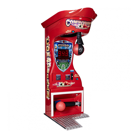
- Page 3 DOCUMENT FOR SAFE AND LONG LASTING MACHINE USAGE. 2. Usage/Purpose Comboboxer is a punch-force and kick-force measuring machine. The machine is designed to allow players to choose between two game types: boxing and kicking. This machine allows to measure punch-force (boxing power game), kick-force (kicker power game) and play a power tournament game between up to 6 players, either as a boxing game or kicking game.
- Page 4 Width [in] Height [in] Overall Mass [Lb] Power consumption [Wh] 4. Assembly/ Construction description Punch-force and kick-force measuring machine Comboboxer is built out of three main components: - base, - middle assembly, - top assembly. The key component is a mother board (electronic board) placed inside Boxer’s body (block schematics drawing #1) to which...
- Page 5 - power supply (drawing #4 and drawing #5) – consists of transformer, fuses and broadcasters that control alarm sirens & electromagnet – transforms voltage from 110 V to 12 V (connected to main board J6), - measuring mechanism – consists of sending and receiving diodes that measure blade fly speed through assembly, - verbal information mechanism –...
- Page 6 5. Transport Machine should be transported in vertical position. Machines are shipped on a wooden 41” x 53” palette, and sides are covered with special thick (~3/8”) multi-layer cardboard 93” tall (from the bottom of the pallet). The total weight of the box is approx. 491 lbs. After machine is taken out of the box, it should be transported in horizontal position with the help of two wheels.
- Page 7 7. Usage instructions a) It is recommended to use warm up punches before the maximum strength punch. b) For the first time user, please practice with several easy test punches before your maximum punch. c) Read the user instructions placed on the machine, d) Select type of game (default setting is power mode for both, the boxing and the kicking game) by pressing SELECT GAME button 2 Players...
- Page 8 Before pressing the START button player must stand in front of the Comboboxer. f) Start game (Boxer or Kicker/Soccer) by either pushing ‘Start boxing’ (for Boxer) or ‘Start Kicking’ (for Kicker/Soccer) button.
- Page 9 8. Maintenance check list, problem prevention and day-to-day conservation Every two weeks (recommended): - check the air pressure of the bag and the ball - it should be NO MORE than 2psi, no less than 1.5psi, - check if the bag is not rotating about its own axis. If it is, see point D in this section, - check the position of the arm protectors (see point H in this section),...
- Page 10 B) Sound volume regulation R362 potentiometer (see drawing #1) used to control volume is placed on the right side of the electronic board. The volume adjustment can be done by rotating the potentiometer to the left or right. C) Maintenance of mechanism and regulating spring Periodically (once a month or more often, or if the lowering speed of punching bag or kicking ball is fairly low) all moving elements should be rubbed/ sprayed with WD-40 or grease.
- Page 11 rope, take out old insert and replace it with a new rubber bladder. A special attention must be paid to the location of the bladder valve. The valve must be placed in the opening of the leather cover. F) Bulb replacement, GAME button In case of bulb failure in the GAME button one should take out micro- switch from the casing (by slight turn and then pull) and then proceed with bulb replacement [bulb spec: 12 Volt &...
- Page 12 The following two pictures illustrate an improper setup of the punching bag. NEVER leave the machine in this state. The picture on the left shows the arm protector placed too high. The second picture shows the missing arm protector. Both of these cases may result in serious injury to the user.
- Page 13 9. Quick check for potential errors Main board not functioning: Check all fuses (5A). Check the connection between main power supply and the main board. Make sure that the main processor and other connectors are well seated. All displays can be checked by turning the switch #1 to “ON” position than turning machine off and back on.
- Page 14 Sensor is not functioning: Check sensors in service mode (first press “Start Boxing” [when checking Boxer] or press “Start Kicking” [when checking Kicker/Soccer] and use switch #1 on the main board (S1) and manipulate button SW1 go to mode P07), if punching bag (while checking Boxer) or kicker arm (while checking Kicker/Soccer) is moving UP/DOWN and on the main board (depending on bag/arm position) HI –...
- Page 15 Power supply is refusing to work: Check if “car” fuse in power supply is not burned (30A). Check if transformer cable is correctly hooked up to power supply socket. Machine is not starting: Check power cable & fuse 5A. Check if ON/OFF switch (filter) is not damaged. Counter is showing Err: Check if mechanical counter did not come loose (then turn the machine OFF and ON).
- Page 16 Red diode active on main board: Usually caused by circuit being shorted at scale bulb array, check all cables for potential shortage.
- Page 17 10. Machine setup Main Board Layout (Back Side) Drawing #1...
- Page 18 List of connectors: J1 – connector for coin acceptor J2 – connector for bill acceptor J3 – connector for power supply to bill acceptor, ticket dispenser, capsule dispenser, thermal printer J4 - connector for ticket dispenser, capsule dispenser, thermal printer J5 &...
- Page 19 Dip Switch 1-8 (S1) HE RED BLACK OR BLUE SWITCH BOX WITH SWITCHES IS LOCATED ON THE LEFT SIDE OF THE MAIN CIRCUIT BOARD "ON" PROGRAM SWITCH MUST BE SET TO POSITION WHEN “ ”. MACHINE IS Switch #1 SW1 & SW2 SW1 ↑...
- Page 20 TEMPORARY COUNTER OF POINTS. 1 POINT = $.25 (25 CENTS). YOU CAN RESET IT TO 0000 BY PUSHING AND HOLDING THE "START BOXING" BUTTON FOR 3 SECONDS. COUNTER OF POINTS. THIS IS LIFE LONG - NOT ERASEABLE. ELECTRONIC COUNTER OF REVENUE (COUNTS THE QUOTERS WHILE THE MECHANICAL COUNTER IS DISCONNECTED).
- Page 21 THIS FUNCTION IS USED FOR TESTING OF THE SENSOR (DIAGNOSTIC FUNCTION). WHEN PUNCHING BAG IS IN THE VERTICAL POSITION - THE DISPLAY SHOWS - "LO", WHEN PUNCHING BAG IS IN THE HORIZONTAL POSITION - DISPLAY SHOWS "HI”. YOU CAN SET THE BEST SCORE WHICH WILL BE ON THE DISPLAY FOR POWER MODE ONLY.
- Page 22 SETS HOW MANY TICKETS WILL BE GIVEN FOR 1 CREDIT (RANGE FROM 0-5, DEFAULT SETTING 5). SETS HOW MANY TICKETS FOR THE HIGHEST SCORE (RANGE FROM 0-20, DEFAULT SETTING 5). “BREAKING POINT”- BP. SETTING THAT WOULD ENABLE THE TICKET DISPENSER TO START GIVING OUT THE TICKETS (RANGE FROM 0-990).
- Page 23 BELOW 2 EXAMPLES. ESULT ON ESULT ON ICKETS ICKETS DISPLAY DISPLAY P14 = TICKET = 0 P14 = TICKET = 600 P15 = TICKET= 0 P15 = TICKET = 10 P16 = TICKET=40 P16 = TICKET = 40 P17 = TICKET= 1 P17 = TICKET = 2...
- Page 24 YOU CAN SET 0-10 BONUS CREDITS FOR BREAKING RECORD (USE THE “START BOXING” BUTTON). DEFAULT SETTING IS 1. YOU CAN CLEAR THE CREDITS BY PUSHING THE “START BOXING” BUTTON. COUNTER OF FREE PUNCHES WHICH YOU ACTIVATE BY PUTTING DIP SWITCH # 2 TO “ON” POSITION. COUNTER OF THE BROKEN RECORDS (HIGHEST SCORES) (CAN BE RESET BY PRESSING &...
- Page 25 FREQUENCY OF WINNING - FOR PRIZE #1. THIS REPRESENTS THE NUMBER OF POINTS (QUARTERS) ACCUMULATED BEFORE THE POSSIBILITY OF WINNING THE PRIZE. REACHING THIS NUMBER DOES NOT GUARANTEE A WINNER, HOWEVER IT INCREASES THE CHANCES OF WINNING (RANGE 0-10000, DEFAULT SETTING 1200).
- Page 26 NUMBER OF FREE CREDITS AWARDED FOR PRIZE #2 CAN BE ASSIGNED USING THIS OPTION. THIS NUMBER CAN BE SET IN THE RANGE OF 0-50, DEFAULT SETTING: 1. NOT USED. NUMBER OF TICKETS GIVEN FOR PRIZE #1 CAN BE ASSIGNED USING THIS OPTION. THIS NUMBER CAN BE SET IN THE RANGE OF 0-50, DEFAULT SETTING: 5.
- Page 27 IF SET TO ‘1’ THE TICKET FROM THE THERMAL PRINTER (IF INSTALLED) WILL BE PRINTED FOR THE HIGHEST SCORE (PRIZE #4). IF SET TO ‘0’ NO TICKET FOR THE HIGHEST SCORE WILL BE PRINTED. DEFAULT SETTING: 1. FREQUENCY OF WINNING THE FIRST MAGIC NUMBER (PRIZE #5).
- Page 28 VALUE BY WHICH THE HIGHEST SCORE WILL BE LOWERED (SETTING WHICH WORKS WITH P49, RANGE 0-50, DEFAULT VALUE: 2). IF SET TO 1 ACTIVATES OPTION P52. DEFAULT SETTING: 0. SETTING OF THE HIGHEST SCORE (BREAK POINT) ABOVE WHICH SURPRISE BALL (CAPSULE) WILL BE DISPENSED (RANGE 100-900, DEFAULT SETTING: 500).
- Page 29 UPPER SCORE LIMIT FOR RANGE PRIZE #1 (RANGE 900-999, DEFAULT SETTING: 950). NOTE: Settings in P59 to P64 cannot overlap. For example if the lower limit for range prize #1 is 900, the upper limit for range prize #2 must be less than 900 and so on. IMPORTANT: THIS GAME MODE IS ACTIVATED WITH P23 = 3.
- Page 30 TIME SETTING FOR SENDING INFORMATION USING THE BOXNET FUNCTION. TIME IS GIVEN IN FOLLOWING FORMAT: HH.MM.SS, FOR EXAMPLE 05.25.00 MEANS DATA FROM MACHINE WILL BE SENT EACH 5 HOURS 25 MINUTES. P67 = 0; FUNCTION IS OFF, NO DATA IS SENT, P67 = 00.00.05...00.01.00;...
- Page 31 PRINT PRIZE #3 (1 = PRINT, 0 = DON’T PRINT). DEFAULT SETTING : 0. WORKS FOR P23=3. FACTORY SETTING. FACTORY SETTING. FACTORY SETTING. ACTIVATION OF SURPRISE BALL (CAPSULE) DISPENSER WHEN PLAYER REACHES 100, 200, 300…900 POINTS OR 111, 222, 333… 999 POINTS, AS FOLLOWS: 0 - THE FUNCTION IF OFF, 1 - THE SURPRISE BALL (CAPSULE) DISPENSER IS ON FOR MULTIPLES OF 100 SUCH AS 100, 200 …900 AND FOR...
- Page 32 RELAX – TIME FOR WHICH HALOGEN LAMP WILL BE ON (RANGE 0-5 SECONDS), JUMP 0.1 SECOND). P81=0.0 - THE FUNCTION IS OFF, HALOGEN WILL NOT SHINE. P81=0.1...5.0 - HALOGEN SHINES. - Example: when P81=0.4 it means the halogen lamp will be ON for 0.4 second.
- Page 33 ACTIVATION OF THE FUNCTION ASSISTING IN WINNING THE SURPRISE BALL (CAPSULE) SET IN P77. THE SETTING DEFINES THE RANGE OF POINTS, 0 TO 10, WHICH ARE BEING USED TO ACHIEVE THE WINNING NUMBER. WHEN SET TO 0 THE FUNCTION IS OFF. DEFAULT VALUE: 0 – NO HELP SCORING PRIZES.
- Page 34 SETTING SIREN FOR RECORD BREAKING. THIS SETS THE DURATION TIME OF SIREN SIGNAL. 0 - THE FUNCTION IS OFF. 1..20 - SECONDS FOR WHICH SIREN WILL BE ON (1 SECOND SKIP). SETTING SIREN FOR BREAKING POINT. THIS SETS THE DURATION TIME OF SIREN SIGNAL. 0 - THE FUNCTION IS OFF.
- Page 35 Switch #2 WHEN “ON” MACHINE IS SET FOR FREE PUNCH/ KICK. Switch #3 IF ON “DEMO” WILL PLAY EVERY 2 MINUTES, WHEN THE MACHINE IS NOT USED. IF “OFF” THE SOUND IS TURNED OFF. Switch #4 WHEN “ON” THE HIGHEST SCORE FOR EACH GAME WILL BE RESET AFTER YOU PUSH THE “START BOXING”...
- Page 36 Sensitivity switch (S2). THE SENSITIVITY CAN BE CHANGED BY ROTATING SWITCH S2. AFTER THE SWITCH IS ROTATED THE SENSITIVITY LEVEL WILL BE SHOWN ON THE CREDIT DISPLAY. LOWER LEVEL NUMBERS CORRESPOND TO GREATER DIFFICULTY.
- Page 37 Main Board Layout (Front) Drawing #2 Drawing #3...
- Page 38 Boxer Power Supply Layout: Drawing #4 Kicker Power Supply Layout: Drawing #5...
- Page 39 Main Power Supply Layout: Front view Drawing #6 Mechanical counter 2 – wire from mechanical counter 1 – wire from mechanical counter Drawing #7...
- Page 40 Sensor 1- Emitter 2- Cathode 3- Anode 4- Collector Drawing #8...
- Page 41 Speaker 1 - speaker 2 - speaker 3 - unused 4 - unused Drawing #9 Buttons Start Boxing & Game 1 & 2 – START game (Boxer) 3 & 4 – GAME selection 5 & 6 – bulbs lighting button Start 7 &...
- Page 42 Ticket dispenser 2 - red (+12V) 6 - green (signal) 3 - black (-12V) Drawing #10 Hopper Motor Hopper Drawing #11 Thermal printer Thermal printer Hopper Main board Drawing #12...
- Page 43 1 – tournament (-) 2 – tournament (+) 3 – 100 (-) 4 – 100 (+) 5 – 300 (-) 6 – 300 (+) 7 – 500 (-) 8 – 500 (+) 9 – 700 (-) 10 –700 (+) 11 – 900 (-) 12 –...
- Page 44 Paper Money Depositor 1 – Credit relay (Common) normally purple. Pin#8 at the ICT connector 2 – +12V (Power) normally red. Pin#5 at the ICT connector 3 – GND (Power) normally orange. Pin# 9 at the ICT connector 4 – Credit relay (N.O) normally blue. Pin# 7 at the ICT connector 11.
- Page 45 14. Step by step setup and maintenance instructions HOW TO ACCESS QUICKLY RESETABLE (P01) AND NOT RESETABLE (P02) MONEY COUNTERS P01 and P02 counters can be checked (at the same time) without going into service program, by pressing switch SW1 ↑. The SW1 switch is located in the lower left part of the main board, right above ribbon cable connecting main board with side power supply (small board).
- Page 46 main display P01 will appear. At that time bills and coins can be inserted for a test. After inserting every single coin (bill) testing time will be extend for another 15 seconds. If the testing mode is not used for 15 seconds, machine will switch to regular working mode. HOW TO SET-UP PRICE OF THE GAME PLAY.
- Page 47 Press the SW1 button repeatedly on the main board until the main display reads ‘P 4’. If you get too far on this menu you can always get back with the SW2 button. Now you can modify the setting to set-up the price of the game play ( If one game credit is to cost $1 the setting would then be 4 -1, meaning that 4 quarters equals one punch).
- Page 48 HOW TO SET UP BONUS POINTS Enter the settings mode by powering up the machine and switching DIP switch #1 to ON position. DIP switch #1 The main display should now indicate the settings mode with ‘P 1’ as shown. Press the SW1 button repeatedly on the main board until the main display reads ‘P 5’.
- Page 49 This setting corresponds to the number of credits given when a set dollar amount is put in the machine. For example: you want to set 8 credits (punches) for $5 (5*4=20 quarters), you should adjust this setting to indicate 20-8 as shown. The values can be set using START and GAME buttons.
- Page 50 HOW TO SET UP MAGIC NUMBER The magic number can be any 3 digit combination. The magic number as well as the frequency of hitting that number must be set. Enter the settings mode by powering up the machine and switching DIP switch #1 to ON position.
- Page 51 Press the SW1 button repeatedly on the main board until the main display reads ‘P43’. If you get too far on this menu you can always get back with the SW2 button. Use the START BOXING and GAME buttons to adjust the value of the magic number as desired.
- Page 52 To leave the settings mode simply turn the DIP switch #1 to off (left) position. The machine should reset and be ready to go. HOW TO RESET HIGH SCORES MANUALLY If you feel the score on the game reached an unbeatable number you can reset this score to the default value (see setting P30).
- Page 53 HOW TO RESET HIGH SCORES AUTOMATICALLY If you want the machine to automatically reset the highest score (of Power Mode) so that it does not get too high, follow the instructions below. The highest score will be reset to the value programmed in setting P30 (see setting P30).
- Page 54 Press the SW1 button repeatedly on the main board until the main display reads ‘P86’. If you get too far on this menu you can always get back with the SW2 button. Using START BOXING button on the front of the machine set number of hours (counted from the last resetting) after which the highest score should be reset automatically, eg.
- Page 55 machine is in idle state for more than 15 minutes the highest score will be reset. HOW TO ERASE CREDITS Erasing the game’s credits can be done with the following procedure. Enter the settings mode by powering up the machine and switching DIP switch #1 to ON position.
- Page 56 Press the SW1 button repeatedly on the main board until the main display reads ‘P20’. If you get too far on this menu you can always get back with the SW2 button. Press the START BOXING button located in the front of the game. When finished don’t forget to set DIP switch #1 back to OFF position.
- Page 57 Tension nut Counter lock nut To install a new bag first make sure that the tension nut is taken off and the second nut is screwed all the way on the bolt. Otherwise the second bolt will prevent the bag from properly tightening of the assembly.
- Page 58 If it is secured tight enough, then finish by unscrewing the second nut until it tightens on the metal arm. HOW TO RELEASE THE PUNCHING BAG MANUALLY Sometimes it is necessary to release the punching bag when the machine has no power. This can still be done manually. You must reach over the bag and find the mechanical hammer holding the entire arm in position.
- Page 59 HOW TO CHECK THE SOLENOID Proper operation of either of solenoids can be verified by releasing the punching bag (when checking Boxer) or kicker/soccer arm (when checking Kicker/Soccer) electronically. This can be done by first pressing by pushing a release button located on the side power supply (not the main board).
- Page 60 Solenoid Wires Check resistance on these two terminals with a multi-meter. The resistance should be very low around 0.5 Ω. If your meter shows overload or infinite resistance the solenoid coil may be damaged. In that case replacing the solenoid is necessary. The solenoid can be evaluated in another way if for example you do not have a multi-meter handy.
- Page 61 MAIN BOARD SETTINGS...
- Page 62 MAIN BOARD SETTINGS...
- Page 63 Date of Service Punching bag condition Punching bag pressure Arm protector condition Arm protector position Legibility of disclaimer Legibility of instruction Level of machine Grease on mechanism Bulbs Buttons Bill and coin validators Safe condition (Yes/No) If not working or condition not safe for use what was replaced...
- Page 64 Date of Service Punching bag condition Punching bag pressure Arm protector condition Arm protector position Legibility of disclaimer Legibility of instruction Level of machine Grease on mechanism Bulbs Buttons Bill and coin validators Safe condition (Yes/No) If not working or condition not safe for use what was replaced...
Need help?
Do you have a question about the Comboboxer and is the answer not in the manual?
Questions and answers
The combo boxer screen keeps saying hlp after every play flashing on the screen. What does it mean and how do we get it to go away