
Related Manuals for Kalkomat BOXER


Summary of Contents for Kalkomat BOXER
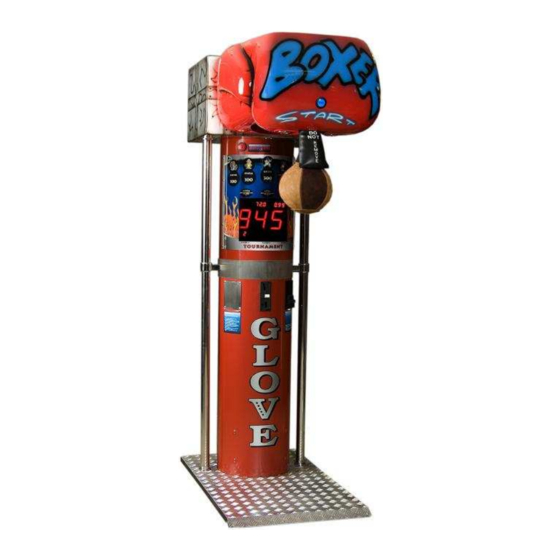
- Page 1 _______________________________________________ KALKOMAT _______________________________________________ BOXER Punch-Force measuring machine Technical Information BOX 2...
-
Page 2: Table Of Contents
Index: 1. Introduction ................... 3 2. Usage/Purpose ................3 3. Technical Data................4 4. Assembly/ Construction description ..........4 5. Transport..................6 6. Installation ..................6 7. Usage instructions ................7 8. Maintenance check list, problem prevention and day-to-day conservation ................8 9. -
Page 3: Introduction
1. Introduction Main purpose of this Technical Information is to: - familiarize user with machine construction, - provide proper setup parameters, installation and power line hookup, - familiarize user with proper and safe usage procedures, exploitation and conservation. WARNING! USER MUST FOLLOW ALL GUIDELINES INCLUDED IN THIS DOCUMENT FOR SAFE AND LONG LASTING MACHINE USAGE. -
Page 4: Technical Data
3. Technical Data Model Depth [in] Width [in] Height [in] Overall Mass [Lb] Power consumption [Wh] 4. Assembly/ Construction description Punch-force measuring machine Boxer is built out of three main components: - base, - middle assembly, - top assembly. - Page 5 The key component is a mother board (electronic board) placed inside Boxer’s body to which mechanical elements and user interface components are connected. Electric/ electronic part contains following: - power supply – consists of transformer, fuses and broadcasters that control...
-
Page 6: Transport
- coin acceptor – used to deposit coins (can be reprogrammed to tokens or other currencies), - bill acceptor – used to deposit bills, - mother board. 5. Transport Machine should be transported in vertical position. Machines are shipped on a wooden 41” x 53” palette, and sides are covered with special thick (~3/8”) multi-layer cardboard 93”... -
Page 7: Usage Instructions
Make sure that there is enough clearance on the sides and in front of the machine, so the player will not hit any objects or person after punching the bag. Recommended safety radial distance if 5 feet from the point where the bag drops to the lower position. -
Page 8: Maintenance Check List, Problem Prevention And Day-To-Day Conservation
Before pressing the START button player must stand in front of the Boxer. c) After pressing the START button player has to wait in front of the machine for the punching bag to be released from the upper position. - Page 9 - check the position of the arm protector (see point H in this section), - check all of the connections on the main board, - check the level/ balance of the machine (if needed, use adjusting legs under the machine to bring the machine to level), - check if the usage instructions and disclaimers are readable.
- Page 10 adjustment can be done by rotating the potentiometer to the left or right. C) Maintenance of mechanism and regulating spring Periodically (once a month or more often, or if the lowering speed of punching bag is fairly low) all moving elements should be rubbed/ sprayed with WD-40 or grease.
- Page 11 The valve must be placed in the opening of the leather cover. F) Bulb replacement, GAME button In case of bulb failure in the GAME button one should take out micro-switch from the casing (by slight turn and then pull) and then proceed with bulb replacement [bulb spec: 12 Volt &...
- Page 12 The following two pictures illustrate an improper setup of the punching bag. NEVER leave the machine in this state. The picture on the left shows the arm protector placed too high. The second picture shows the missing arm protector. Both of these cases may result in serious injury to the user.
-
Page 13: Quick Check For Potential Errors
9. Quick check for potential errors Main board not functioning: Check all fuses (5A). Check the connection between power supply and the main board. Make sure that the main processor and other connectors are well seated. The main display can be checked by turning the switch #1 to “ON”... - Page 14 Coin Acceptor is not functioning: Check if it is not clogged up. Check for dust and dirt. Check strip connecting the main board with the acceptor. Mechanism is not functioning: Using just power supply check if it is possible to lower punching bag (using manual switch, black button above the 12V connector).
- Page 15 2. TWO PUSH BUTTONS (S2) AND (S3). THEY ARE LOCATED IN THE LOWER LEFT PART OF THE MAIN CIRCUIT BOARD. DURING REGULAR USAGE OF THE BOXER ALL THE SWITCHES MUST BE IN “OFF” POSITION EXCEPT SWITCH #4 FUNCTION OF SWITCHES (S1): SWITCH #1 WHEN “ON”...
- Page 16 PROGRAM P01-P07. DESCRIPTIONS FOR EACH PROGRAM ARE LISTED BELOW. SERVICE KEY – YOU CAN BROWSE THROUGH P01-P07 BY PRESSING S2 OR S3 YOU WILL SEE P01-P07 ON THE MAIN DISPLAY (FRONT OF BOXER). REMEMBER FOR SOME SETINGS YOU WILL HAVE TO USE “START” OR “THE GAME”...
- Page 17 FOR DIAGNOSTIC ON THE POWER SUPLLY CIRCUIT BOARD (THE LOWER ONE) YOU WILL FIND THE SMALL, BLACK PUSH BUTTON (UPPER LEFT SIDE) - IT IS USED TO RELEASE THE PUNCHING BAG FROM THE UP POSITION WITHOUT USING THE MAIN CIRCUIT BORD - THE POWER GOES STRAIGHT TO ELECTROMAGNET AND THE BAG IS RELEASED.
Need help?
Do you have a question about the BOXER and is the answer not in the manual?
Questions and answers