Table of Contents
Advertisement
Advertisement
Table of Contents

Related Manuals for Serpent SRX4 Gen3


Summary of Contents for Serpent SRX4 Gen3
-
Page 2: Table Of Contents
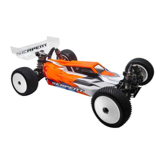
REaD ThIS fIRST! The Serpent SRX4 Gen3 is a state of the art 1/10 scale 4wd buggy. which will give you the true Serpent - This is a highly technical hobby product, intended to be used in a safe racing environment. This car racing experience. - Page 3 hOW TO USE ThE maNUal lINES DESCRIpTION ICONS DESCRIpTION Each step contains a variety of numbers, lines, and symbols. The numbers represent the order in Each step contains a variety of symbols described below. which the parts should be assembled. The lines are described below. Step number;...
-
Page 4: Rear Diff Assembly
REaR DIff aSSEmbly STEp 1 STEp 2 STEp 3 DIff bag RR 1.5x8 Add just enough oil to cover the large gear before assembling the small satellite gears and cross pins. Use the silicone oil supplied in the kit. For the correct cst value please check the default setup-sheet. - Page 5 STEp 4 STEp 5 Fit the o-ring before Fill the differential to the brim with silicone oil , do NOT overfill. M2x10 finishing the filling of the differential. Use the silicone oil supplied in the kit. For the correct cst value please check the default setupsheet.
-
Page 6: Front Diff Assembly
fRONT DIff aSSEmbly STEp 6 STEp 7 STEp 8 DIff bag fR 1.5x8 Add just enough oil to cover the large gear before assembling the small satellite gears and cross pins. Use the silicone oil supplied in the kit. For the correct cst value please check the default setup-sheet. - Page 7 STEp 9 STEp 1O Fit the o-ring before Fill the differential to the brim with silicone oil , do 1O.1 1O.2 M2x10 finishing the filling of NOT overfill. the differential. Use the silicone oil supplied in the kit. For the correct Apply some CA glue to fix cst value please check the default setupsheet.
-
Page 8: Center Chassis Assembly
CENTER aSSEmbly STEp 11 STEp 12 bag 1 M3x8 M3x8 M3x8 SUSPENSION INSERTS M3x18 M3x8 M3x8 Please find qty. 2 Centered Inserts. These 0 inserts are the default setup and should be M3x8 installed into this RR FR Toe block. Additional information can be found on page 21, for how you can use the inserts to adjust toe-in, anti-squat, and pivot width. - Page 9 STEp 13 13.1 13.2 SUSPENSION INSERTS Please find qty. 2 Centered Inserts. These 0 inserts are the default setup and should be installed into this FR RR Toe block. Additional information can be found on page 28, for how you can use the inserts to adjust toe-in, anti-squat, and pivot width. M3x8 M3x8 M3x8...
- Page 10 STEp 14 STEp 15 Please notice that there are two types 14.1 14.2 of plastic guide mounts, low and high. HIGH 3x12 3x5x0.3 HIGH 3x6x2.5 3x5x0.3 3x6x2.5 3x5x0.3 M3x6 M3x6 M3x6 M3x6 M3x6 3x6x2.5 3x5x0.3 M3x6 M3x6...
-
Page 11: Transmission Assembly
TRaNSmISSION aSSEmbly STEp 17 STEp 16 bag 2 17.1 5x10x4 5x10x4 5x13x4 M3x14 17.2 M2.3x4 M3x14 M2.3x4 5x10x4 5x13x4... - Page 12 STEp 18 STEp 19 19.1 5x8x2.5 Nylock Nut M3 19.2 M3x12 3.2x7x0.5 1.5x8 SLIPPER INITIAL SETTING 1.5 - 2 mm Please notice the orientation of plate. 1.5x8 Nylock Nut M3 M3x12 3.2x7x0.5 5x8x2.5...
- Page 13 STEp 2O STEp 21 M3x8 M3x8 M3x8 M3x8 M3x8...
- Page 14 STEp 22 STEp 23 bag 3 DIFF INSERTS CHART M3x25 HIGH HIGH 10x15x4 M3x10 10x15x4 M3x25 REAR SHOCKS DEFAULT POSITION M3x25 M3x10 M3x25 M3x25 10x15x4...
- Page 15 STEp 24 STEp 25 2x12 2x12 M3x25 5x13x4 M3x8 2x12 M3x8 M3x25 5x13x4...
- Page 16 STEp 26 STEp 27 bag 4 Assembly order: 1- Install the belt onto the LSD slipper pulley. 2- Roll the belt onto the 36t pulley. 3- Install the flange. 4- Assemble the circlip. M3x8 M3x10 M3x8 M3x10...
- Page 17 STEp 28 STEp 29 M3x16 DIFF INSERTS CHART HIGH HIGH Assembly order: 1- Install the front belt onto center 21t layshaft pulley. 10x15x4 2- Install ballbearings and diff inserts onto the front diff. 3- Loop onto the front differential. 4- Slide Front differential with inserts into final bulkhead position. 10x15x4 5- Install transmission case top and sway bar mount.
- Page 18 STEp 3O STEp 31 M3x8 M3x20 M3x28 Flanged M3x10 M3x12 FRONT SHOCKS DEFAULT POSITION M3x8 M3x20 M3x10 M3x12...
-
Page 19: Rear Assembly
REaR aSSEmbly STEp 32 bag 5 REAR AXLE HEIGHT AND OFFSET INSERTS Wide Offset Narrow 10x15x4 0.5mm 0.5mm 5x13x4 1.5mm 1.5mm 2x10 2x10 M2x5 2.5mm 2.5mm REAR WHEEL-AXLE PIN FOR DRIVESHAFT POSITION 1) The axle height adjustment will give you the ability to adjust the roll Mount pin in middle hole by default The axle has 3 pivoting center for various traction conditions. - Page 20 STEp 33 STEp 34 Notice, the uprights are symmetrical, but the 3x6x1 camber link mount has to have the proper orientation for Left and Right. Please check below the proper orientation. 3x6x0.5 FRONT LEFT RIGHT 3x6x1 3x6x0.5 REAR 3x33 M3x12 M2.3x4 REAR UPRINGHT SHIMS AND OFFSET...
- Page 21 STEp 35 bag 6 REAR SUSPENSION INSERTS Below is a diagram of every possible orientation of the compete 7 inserts system. You are able to move 0.5 or 1 degree in any direction from center. We also have 2 special inserts to fill 0.5° left and right offset, by 1°...
- Page 22 STEp 36 STEp 37 36.1 M3x3 4x7x2.5 Flanged M3x14 M3x3 1.3mm 4x7x2.5 Flanged 36.2 M3x3 BALLSTUD LENGTH M3x3 M3x14 4x7x2.5 Flanged...
- Page 23 STEp 38 38.1 18.65mm 38.2 BALLSTUD LENGTH 14.65mm 18.65mm 14.65mm 3x6x1 3x6x0.5 FRONT CAMBERLINK LENGTH 27.5 mm CAMBERLINK INNER & OUTER DEFAULT POSITION 3x6x0.5 3x6x1...
- Page 24 STEp 39 M3x12 M3x22 M3x12 M3x22...
-
Page 25: Front Assembly
fRONT aSSEmbly STEp 4O STEp 41 bag 7 M3x8 5x8x2.5 5x8x2.5 M3x10 M3x10 M3x8 M3x10 5x8x2.5... - Page 26 STEp 41 M3x6 42.1 42.2 STEERING LINK LENGTH The length may differ slightly per 1- Check how many teeth your servo servo-brand. M3x12 M3x6 spline has (23 or 25) and then install the correct lever. 2- Make sure to put the servo in neutral 3x5x1 before mounting the lever.
- Page 27 STEp 43 bag 8 1- Place the caster shims in the bushings 43.1 43.3 STEERING ARM 2- Place the bushings and shims onto the casterblock. CHART 3- Slide the steering block assembly onto the caster- block and fix with the M3x12 screws. ACKERMANN ACKERMANN M3x12...
- Page 28 STEp 45 bag 9 FRONT SUSPENSION INSERTS Below is a diagram of every possible orientation of the complete 7 insert system. You are able to move 0.5 to 1 degree in any direction from center. We also have two special inserts to fill 0.5° left and right offset,by 1°...
- Page 29 STEp 46 STEp 47 46.1 47.1 FRONT CAMBERLINK STEERING TRACKRODS LENGTH LENGTH 27.9 mm 27.5 mm 46.2 47.2 18.65mm 16.65mm Nylock Nut M3 Flanged 3x6x1 3x6x0.5 3x6x1 14.65mm BALLSTUD LENGTH Nut M3 BALLSTUD LENGTH 16.65mm 18.65mm 16.65mm 16.65mm 14.65mm 3x6x1 Nylock Nut M3 3x6x1 Nut M3...
- Page 30 STEp 48 STEp 49 M3x3 M3x3 M3x3 1.2mm M3x3 M2.5x6 BALLSTUD LENGTH M2.5x6 VIEW DETAIL 2.5mm M3x3 M3x3 M2.5x6...
-
Page 31: Shocks Assembly
ShOCkS aSSEmbly STEp 5O STEp 51 bag 1O fR ShOCkS / bag 11 RR ShOCkS 5O.1 51.1 2.5x6x0.5 Note the correct orientation of the Use some silicone oil shock spacers . during the assembly. For the correct piston holes and size Nut M2 please check the default setupsheet. - Page 32 STEp 52 STEp 53 52.1 52.2 SHOCKS LENGTH: Measure the Assemble the spring and spring- shock length fully extended. cup (align correctly) to complete 1-Bleed: push the shock- 1- Fill up with sillicone oil FRONT REAR the shock. rod all the way in slowly, fully using the silicone to allow excessive oil to oil supplied in the kit.
- Page 33 STEp 54 STEp 55 bag 12 M3 Plastic M3 Plastic Do not overtighten and Do not overtighten and smash bushing with the smash bushing with the Nut Flanged Nut Flanged nut and note orientation of nut and note orientation of the lower shock pivot ball.
-
Page 34: Final Assembly
fINal aSSEmbly STEp 56 STEp 57 Use double sided tape to mount the ESC and RX to the chassis. M3x8 3.2x7x0.5 M3x8 Pinion is not included in the kit. Assemble the proper pinion for your set-up. M3x8 3.2x7x0.5... - Page 35 STEp 58 STEp 59 ANGLED WING M3x12 M3x8 SPACERS CHART 0º 2º M3x8 4º 6º 8º FRONT REAR M3x8 M3x12...
- Page 36 STEp 6O 1- Rims included in the kit. 2- Rubber tyres not included in the kit. 3- Be sure to glue your rubber tyres to the wheels using Cyanoacrylate glue. Nut M4 Flanged Nut M4 Flanged...
-
Page 37: Exploded Views
ShCOkS EXplODED VIEW aNTI-ROll baRS EXplODED VIEW CENTER ChaSSIS aSSEmbly EXplODED VIEW mID-fRONT TRaNSmISSION EXplODED VIEW STEERINg SERVO aSSEmbly EXplODED VIEW REaR TRaNSmISSION EXplODED VIEW fRONT SUSpENSION EXplODED VIEW REaR SUSpENSION EXpODED VIEW fINal aSSEmbly EXplODED VIEW TEam SERpENT NETWORk... - Page 38 fRONT aND REaR DIffERENTIal EXplODED VIEW 500790 Geardiff set 51T SRX2 Gen3 500780 500253 500248 500481 500781 opt 500257 110220 500793 opt 500247 500248 500794 opt 500253 110220 500249 500758 opt 500290 500246 500290 500246 500249 500758 opt 500246 110188 411069 Differential balls steel 1/8”...
- Page 39 ShOCkS EXplODED VIEW 500136 500183 500199 opt 500183 500184 110153 500174 FRONT 500175 REAR 500222 opt 500176 500178 500223 opt 500487 500179 500224 opt 500177 500180 opt 500225 opt 500487 500226 opt 500227 opt 500228 opt 500229 FRONT 500230 opt 500231 opt 500232 opt 500233 opt...
- Page 40 500755 Camberlink mount rr alu SRX2 Gen3 500456 Antiroll bar fr 1.3 SRX4 500745 Antiroll bar 1.2 rr SRX2 Gen3 500852 Anti-Roll Bar 1.6mm fr SRX4 Gen3 500457 Antiroll bar fr 1.4 SRX4 500746 Antiroll bar 1.4 rr SRX2 Gen3...
- Page 41 110408 401124 110408 500839 110201 110408 401124 500839 500837 110408 500828 401124 500848 opt 110408 500718 110201 500839 500810 110184 110122 110159 110104 110159 110122 110104 110122 110104 500739 motor weight rr SRX2 Gen3 500848 Battery Support ALU SRX4 Gen3...
- Page 42 mID-fRONT TRaNSmISSION EXplODED VIEW 110124 110124 500826 110170 500815 110142 500805 500136 500137 500830 110302 110104 500830 500814 500820 110215 500816 110183 500829 110229 500841 500827 500817 110501 110501 110127 500484 110215 110503 500729 110104 500840 500829 500729 110302 110503 500827 110183 110104...
- Page 43 500867 opt 500811 500162 500850 opt 500695 500694 110104 500803 110449 110407 500847 Bellcrank L&R ALU SRX4 Gen3 500867 Servo lever 25T alu SRX4 Gen3 500850 Suspension bracket fr-rr L+R brass SRX4 Gen3 500866 Servo lever 23T alu SRX4 Gen3...
- Page 44 500702 500213 Spur gear 70T SRX2 500217 Spur gear 80T SRX2 500272 Wingmount-set SRX2 MM 500856 Slipper Set 24T FT SRX4 Gen3 500214 Spur gear 72T SRX2 500218 Spur gear 82T SRX2 500282 Wingmoung low SRX2 mm 500857 Slipper Pulley 24T FT SRX4 Gen3...
- Page 45 110124 110153 500443 Driveshaft FR 82mm (2) SRX4 Gen3 500858 DJC wheelaxle set fr 76mm (2) SRX4 Gen3 500862 DJC wheelaxle fr (2) SRX4 Gen 3 500822 Steering lever opt 0 (2) SRX4 Gen3 500859 DJC driveshaft fr 76mm (2) SRX4 Gen3...
- Page 46 500751 Suspension bracket wide RR-RR SRX2 Gen3 500539 Wishbone rr L+R SRX2 MM V2 hard 500777 Short offset upright (2) SRX Gen3 500752 Suspension bracket narrow RR-FR brass SRX2 Gen3 500540 Wishbone rr L+R long SRX2 MM 500854 Wheelhexagon 0mm (2) SRX4 Gen3...
- Page 47 500375 Rear wing 7” (2) SRX 500734 Front bulkhead insert alu SRX2 Gen3 500189 Rear wing 6.5” SRX2 500868 Body lightweight SRX4 Gen3 500492 Wing washer alu srx (2) 500252 Rear wing 7.0” SRX2 500622 1/10 buggy rim 4wd FR yellow SDX (2)
-
Page 48: Team Serpent Network
TEam SERpENT NETWORk SPYDER SRX4 GEN3 SPARE PARTS www.serpent.com/500015/spares/ SPYDER SRX4 GEN3 OPTIONALS PARTS www.serpent.com/500015/Optionals/ SERPENT TOOLS www.serpent.com/product/Tools/ SERPENT MERCHANDISING www.serpent.com/product/Merchandising/... - Page 49 SERPENT WEBSITE AND BLOG www.serpent.com www.teamserpent.com www.dragon-rc.com SERPENT PROMO PAGES http://promo.serpent.com SERPENT FACEBOOK GROUPS http://promo.serpent.com/indexfb.htm SERPENT ADVANCED MANUALS http://promo.serpent.com/sam/ SERPENT SOCIAL MEDIA www.facebook.com/SerpentMRC www.youtube.com/user/SerpentMRC www.twitter.com/SerpentMRC www.plus.google.com/+SerpentModelcars/posts www.weibo.com/teamserpent...
- Page 50 Manual SRX4 Gen3 # 89742-1...
Need help?
Do you have a question about the SRX4 Gen3 and is the answer not in the manual?
Questions and answers