Advertisement
Quick Links
Advertisement

Related Manuals for Serpent Cobra SRX8e


Summary of Contents for Serpent Cobra SRX8e
-
Page 2: Table Of Contents
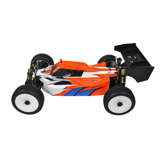
REaD ThIS fIRST! The Serpent Cobra SRX8e is a state of the art 1/8 scale electric 4wd buggy which will give you the true - This is a highly technical hobby product, intended to be used in a safe racing environment. This car Serpent racing experience. - Page 3 hOW TO USE ThE maNUal lINES DESCRIpTION ICONS DESCRIpTION Each step contains a variety of numbers, lines, and symbols. The numbers represent the order in Each step contains a variety of symbols described below. which the parts should be assembled. The lines are described below. Step number;...
-
Page 4: Center Diff Assembly
CENTER DIff aSSEmbly STEp 1 STEp 2 CENTER DIff bag Note the correct M3x4 pin location. 2.5x12 VOLUME COMPENSATORS 6x11.75x0.2 When the differential gets hotter, the foam inserts will absorb the pressure of the expansion of the oil. 1- The supplied foam tube must be cut to size as indicated here below. - Page 5 STEp 3 STEp 4 STEp 5 Fill the differential with silicone oil 1 mm above the crosspin, do NOT M3x14 overfill. Use the silicone oil supplied in the kit. For the correct cst value please check the default setupsheet. 3.5x7x0.1 OIL LEVEL 3.5x7x0.1 AMOUNT OF OIL IN...
-
Page 6: Fr/Rr Diff Assembly
fR/RR DIff aSSEmbly STEp 6 STEp 7 fR/RR DIff bag M3x4 Note the correct pin location. 2.5x12 VOLUME COMPENSATORS 6x11.75x0.2 When the differential gets hotter, the foam inserts will absorb the pressure of the expansion of the oil. 1- The supplied foam tube must be cut to size as indicated here below. - Page 7 STEp 8 STEp 9 STEp 10 Fill the differential with silicone oil 1 mm above the crosspin, do NOT M3x14 overfill. Use the silicone oil supplied in the kit. For the correct cst value please check the default setupsheet. 3.5x7x0.1 OIL LEVEL 3.5x7x0.1 AMOUNT OF OIL IN...
-
Page 8: Rear Assembly
REaR aSSEmbly STEp 11 STEp 12 bag 1 M5x4 5x13x4 8x16x5 M3x14 M3x12 After building the differential with new gears, new differential case and bearings, the Flanged diff may feel a little tight. The connected parts need at least an hour run-time to create a perfect match. - Page 9 STEp 13 STEp 14 13.1 After 1 or 2 hours of running the car, re-check the gear- mesh between the ring gear and the pinion. All parts should have run-in properly. 13x16x0.1 You may add or remove 13x16x0.1 shims as needed. 13x16x0.1 13.2 M3X16...
- Page 10 STEp 15 STEp 16 bag 2 Tighten anti-roll bar cap until 15.1 there is no play, and it moves freely. ANTIROLL BAR ROD LENGTH 34 mm 15.2 M2.5X6 M3X16 REAR TOE IN INSERTS CHART REAR ANTISQUAT INSERTS CHART M2.5X6 M2.5x6 M3x16...
- Page 11 STEp 17 STEp 18 M3X3 M3X3 Make correct holes in the mudguards as required. 5X8X2.5 Flanged M3X8 REAR ANTIROLL BAR ASSEMBLY M3X8 M3x3 M3x8 5X8X2.5 Flanged...
- Page 12 STEp 19 bag 3 19.1 2.5x13 Apply shims size 8x11x0.1 REAR UPRIGHT ROLL and/or 8x11x0.2mm as 13x19x4 CENTER INSERTS CHART needed to remove play. 8x16x5 3x17 MID LOW MID HIGH M5x4 HIGH Note the correct coupler assemby. M3x6 19.2 REAR DEFAULT REAR UPRIGHT WHEELBASE SHIMS POSITION Nylock Nut M3...
- Page 13 STEp 20 bag 4 20.1 REAR CAMBERLINK LENGTH 17.7 mm 20.2 Nylock Nut M3 Flanged REAR CAMBERLINK DEFAULT POSITION M3X20 3.2x7x0.5 M3X20 Nylock Nut M3 Nylock Nut M3 M3x20 Nylock Nut M3 M3x20 3.5x7x0.5 Flanged...
- Page 14 STEp 21 M3X16 Nylock Nut M3X25 Nylock Nut M3 M3x25 M3x16...
- Page 15 STEp 22 M4x20 M4x12 M4x20 M4x12...
-
Page 16: Front Assembly
fRONT aSSEmbly STEp 23 STEp 24 bag 5 24.1 M5x4 13x16x0.1 After 1 or 2 hours 5x13x4 8x16x5 of running the car, re-check the gear- mesh between the ring gear and the pinion. All parts should have run-in properly. You may add or remove 13x16x0.1 13x16x0.1 shims as needed. - Page 17 STEp 25 STEp 26 bag 6 26.1 26.2 Tighten anti-roll bar cap until there is no play, and it moves freely. M2.5X6 ANTIROLL BAR 34 mm ROD LENGTH M3x16 M2.5X6 M2.5x6 M3x16...
- Page 18 STEp 27 STEp 28 M3x3 M3x3 5X8X2.5 Flanged M3x16 FRONT SUSPENSION KICKUP INSERTS FRONT REAR FRONT ANTIROLL BAR ASSEMBLY INSERTS M3x3 M3x16 5X8X2.5 Flanged...
- Page 19 STEp 29 bag 7 29.1 STEERING ARMS Steering arm 2 is Apply shims size 8x11x0.1 and/ included in the kit. or 8x11x0.2mm as needed to 2.5x13 remove play. M3x10 8x16x5 3x17 Note the correct 13x19x4 M5x4 coupler assemby. 34.3 29.2 Align the flat spot on the shaft with the 2.5x5x0.4 grubscrew.
- Page 20 STEp 35 bag 8 35.1 FRONT CAMBERLINK LENGTH 16.7 mm 35.2 Nylock Nut M3 Flanged FRONT CAMBERLINK DEFAULT POSITION M3x20 3.2x7x0.5 M3x20 Nylock Nut M3 Nylock Nut M3 M3x20 Nylock Nut M3 M3x20 3.5x7x0.5 Flanged...
- Page 21 STEp 36 M4x20 M4x12 M4x20 M4x12...
- Page 22 CENTRal aSSEmbly STEp 37 Put thread lock in all the M3x6 screws that fix the sideguards to the chassis. Nylock Nut M3 Nylock Nut M3 M3x6 M3x6 M3x6 M3x10 M3x10 Nylock Nut M3 M3x6 M3x10...
- Page 23 STEp 38 bag 9 Put thread lock in all SHORTY BATTERY CONFIGURATION the M3x10 screws With the SRX8e saddle configuration it is possible to use 2S STANDARD LIPOS, and that fix the battery 2S SHORTY LIPOS in forward and rearward position to change the weight distribution. holder to the chassis.
- Page 24 STEp 39 STEp 40 40.1 M4x10 M4x12 M4x10 M4x12...
- Page 25 40.2 M3x10 M4x10 M3x10 M4x10...
- Page 26 STEp 41 M3x14 M4x30 M3x14 M4x30...
-
Page 27: Steering Assembly
STEERINg aSSEmbly STEp 42 STEp 43 bag 10 43.1 43.2 M3x12 M3x12 3x6x0.5 3x6x0.5 M4x10 Nylock Nut M3 The servo saver spring should preloaded 4.5mm. Also notice the correct orientation of the collar. M4x8 4.5 mm M2x10 M2x10 M3x12 3x6x0.5 Nylock Nut M3 M4x10 M4x8... - Page 28 STEp 44 STEp 45 44.1 M3x20 Note correct orientation of the outer steering balljoints. Note correct position of the conical shim. 6x10x3 11 mm STEERING TRACKROD LENGTH M3x20 44.2 Nylock Nut M3 3x7.5x1 Conical 3x7.5x1 Nylock Nut M3 Flanged 3x7.5x1 3x7.5x1 Conical Conical Note correct position of the...
- Page 29 STEp 46 STEp 47 bag 11 Nylock Nut M3 M4x12 M4x10 M3x14 M3x12 M4x16 M3x10 M3x12 M3x10 M3x14 Nylock Nut M3 M4x10 M4x12...
- Page 30 STEp 48 48.1 48.3 Nut M3 M3x16 Flanged Use enough servo spacers so both servos are flush with the bottom of the radiotray posts. This will Check how many teeth your prevent the servo to touch the servo spline has (23, 24 or 25) and use the right lever.
- Page 31 STEp 49 bag 12 M3x10 M3x10 M3x3 M3x8 M3x3 M3x8 M3x10...
- Page 32 STEp 50 STEp 51 50.1 Pinion is not included in the kit. Assemble the proper pinion for your set-up. M4x10 50.2 M4x10 SADDLE BATTERY PACK M4x10...
-
Page 33: Shock Assembly
ShOCKS aSSEmbly STEp 52 STEp 53 bag 13 fR ShOCKS / bag 14 RR ShOCKS 52.1 53.1 2.5x6x0.5 Note the correct position of the Nylock Nut M2.5 Insert the o-ring o-ring . inside the spring collar. 52.2 Note the correct Use some silicone oil orientation of the during the assembly. - Page 34 STEp 54 STEp 55 54.1 55.3 SHOCKS LENGTH: Measure the Assemble the spring and spring- cup (align correctly) to complete shock length fully extended. Push the membrane 1-Bleed: push the shock. into the shock cap. shockrod all the way FRONT REAR in slowly, to allow excessive oil to escape.
- Page 35 STEp 56 STEp 57 bag 15 M3x25 M3x25 M3x6 M3x6 M3x6 Nylock Nut Nylock Nut M3 Flanged M3x6 M3 Flanged REAR SHOCKS FRONT SHOCKS DEFAULT POSITION DEFAULT POSITION M3x6 M3x6 Nylock Nut M3 Nylock Nut M3 M3x25 M3x25 Flanged Flanged...
-
Page 36: Final Assembly
fINal aSSEmbly STEp 58 M3x18 ANGLED WING SPACERS CHART 2º 4º 6º REAR FRONT M3x18... - Page 37 STEp 59...
- Page 38 2- Before painting the body, apply the precut masking sheet elements to the inside of the body. Follow the cleaning & painting instructions supplied by the polycarbonate paint supplier you choose. M3x5 3- Apply the Serpent and Cobra logo-decals on the body and wing. M3x5 Body Clip...
- Page 39 EXplODED VIEWS INDEX DIffERENTIalS EXplODED VIEW REaR EXplODED VIEW fRONT EXplODED VIEW CENTER EXplODED VIEW STEERINg EXplODED VIEW ShOCKS EXplODED VIEW fINal 1 EXplODED VIEW fINal 2 EXplODED VIEW...
- Page 40 DIffERENTIal EXplODED VIEW 600727 110429 600147 600934 600726 110111 110207 600376 600421 600376 110115 600831 1396 600200 600200 110429 1396 600209 110454 600283 opt 600728 600421 110207 600727 600283 Diff pin 10T alu (2) 600893 Overdrive diff pinion 13T SRX8 600868 Diff set 44T front / rear SRX8 600894 Overdrive diff gear 43T SRX8 600869 Diff set 46T center SRX8...
- Page 41 REaR EXplODED VIEW 600338 opt 600339 opt 600237 110402 600770 600434 opt 110142 600238 opt 600239 opt 110141 600684 opt 600192 110107 600622 opt 110116 600735 600730 opt 600847 600823 600733 110401 600795 600192 110193 600102 600828 600622 opt 600795 600185 110116 600781...
- Page 42 fRONT EXplODED VIEW 600794 110441 600336 opt 600788 opt 600731 opt 600337 opt 600789 600846 110148 600240 600790 opt 600737 600241 opt 600791 opt 600936 110109 600795 600242 opt 600792 opt 600828 600881 opt 600795 600723 110110 600185 110107 1340 110402 110193 110116...
- Page 43 CENTRal INSTRUCTIONS 110109 600932 110112 110124 110109 110109 600937 110112 110402 600421 600929 110402 600947 600957 opt 110108 600948 600930 600421 600958 opt 110183 110402 110127 600929 110102 110127 110108 110183 110102 110102 600957 Driveshaft center rr alu saddle layout SRX8E 600958 Driveshaft center fr alu saddle layout SRX8E...
- Page 44 STEERINg EXplODED VIEW 110102 600943 1606 110105 110109 110184 600939 110112 600754 110116 110124 110127 600941 600830 110125 1321 600939 600180 600751 110146 600764 110402 110152 1321 110407 110402 600827 600227 600170 600939 600941 600178 110402 600764 600178 600751 600764 600940 600827 110159...
- Page 45 ShOCKS EXplODED VIEW 600347 600850 opt 600111 600875 opt 600854 opt 600855 opt 600798 FRONT 600856 FRONT 600158 600799 REAR 600857 opt 600858 opt 600113 600859 opt 600861 opt 600862 opt 600803 600863 REAR 600864 opt 600865 opt 600802 600866 opt 110456 110438 600804...
- Page 46 fINal 1 EXplODED VIEW 600452 opt 600453 opt 600960 600454 opt 600455 opt 600456 opt 600457 opt 110441 600835 600282 opt 110118 600768 110151 600931 110151 600769 600685 110194 600779 600824 600769 600768 600835 600282 opt 110194 110441 600779 600824 110137 600824 600779...
- Page 47 fINal 2 EXplODED VIEW 110159 600263 600833 600301 opt 600825 600143 opt 600277 opt 600439 opt 600222 600440 opt 600297 opt 600826 opt 600840 opt 600872 opt 600942 600771 110157 600772 600222 600297 opt 1601 1601 600222 600297 opt 600620 opt 600621 opt 600297 Wheel-nut 17mm flanged/light (4) 600439 Wing white low 811...
-
Page 48: Team Serpent Network
TEam SERpENT NETWORK SRX8e SPARE PARTS www.serpent.com/600018/spares/ SRX8e OPTIONALS PARTS www.serpent.com/600018/Optionals/ SERPENT TOOLS www.serpent.com/product/Tools/ SERPENT MERCHANDISING www.serpent.com/product/Merchandising/... - Page 49 SERPENT WEBSITE AND BLOG www.serpent.com www.teamserpent.com www.dragon-rc.com SERPENT SOCIAL MEDIA www.facebook.com/SerpentMRC www.youtube.com/user/SerpentMRC www.twitter.com/SerpentMRC www.plus.google.com/+SerpentModelcars/posts www.weibo.com/teamserpent SERPENT PROMO PAGES http://promo.serpent.com SERPENT FACEBOOK GROUPS http://promo.serpent.com/indexfb.htm SERPENT ADVANCED MANUALS http://promo.serpent.com/sam/...
- Page 50 Manual Cobra SRX8e #82925-1...
Need help?
Do you have a question about the Cobra SRX8e and is the answer not in the manual?
Questions and answers