Table of Contents
Advertisement
Advertisement
Table of Contents

Related Manuals for Serpent Cobra SRX8 GTE


Summary of Contents for Serpent Cobra SRX8 GTE
- Page 1 INSTRUCTION MANUAL Instruction Manual...
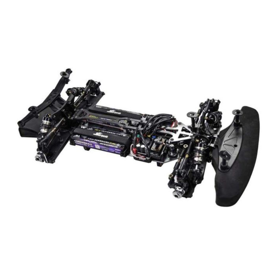
- Page 2 READ THIS FIRST! The Serpent Cobra SRX8 GTE is a state of the art 1/8 scale 4wd GT which will give you the true Serpent racing - This is a highly technical hobby product, intended to be used in a safe racing environment. This car experience.
- Page 3 HOW TO USE THE MANUAL LINES DESCRIPTION ICONS DESCRIPTION Each step contains a variety of numbers, lines, and symbols. The numbers represent the order in Each step contains a variety of symbols described below. which the parts should be assembled. The lines are described below. Step number;...
- Page 4 R/RR DIFF ASSEMBLY STEP 1 STEP 2 FR/RR DIFF BAG M3x4 Note the correct pin location. 2.5x12 VOLUME COMPENSATORS 6x11.75x0.2 When the differential gets hotter, the foam inserts will absorb the pressure of the expansion of the oil. 1- The supplied foam tube must be cut to size as indicated here below.
- Page 5 STEP 3 STEP 4 STEP 5 Fill the differential with silicone oil 1 mm above the crosspin, do NOT M3x14 please check the default setupsheet. 3.5x7x0.1 OIL LEVEL 3.5x7x0.1 AMOUNT OF OIL IN THE DIFFS Use a digital scale to measure the exact amount of oil in the diff.
- Page 6 CENTER SOLID AXLE ASSEMBLY STEP 6 SOLID AXLE BAG Use grease to hold the 8x16x5 o-rings in position. M3x5 8x16x5 M3x3 M3x3 M3x5 8x16x5...
- Page 7 REAR ASSEMBLY STEP 7 STEP 8 BAG 1 REAR ANTISQUAT Tighten anti-roll bar cap until INSERTS CHART there is no play, and it moves freely. ANTIROLL BAR ROD LENGTH 34 mm M2.5X6 M4x12 REAR TOE IN INSERTS CHART M4x12 M2.5X6 M2.5x6 M4x12...
- Page 8 STEP 9 STEP 10 BAG 2 After building the differential with new gears, new differential case and bearings, the diff may feel a little tight. M5x4 The connected parts need at least an hour 10.1 run-time to create a perfect match. Attention: 5x13x4 When you assemble the diff with too much initial play, the gears will not run-in properly...
- Page 9 STEP 11 STEP 12 11.1 5x8x2.5 12.1 flanged M3x3 11.2 M3x3 12.2 M3x18 M3x3 M4x20 DIFF INSERTS CHART M3x25 HIGH HIGH M3x3 M3x25 M3x18 M4x20...
- Page 10 STEP 13 BAG 3 13.1 2.5x13 Note the correct 13x19x4 coupler assemby. 13.2 8x16x5 3x17 8x11x0.1 M5x4 REAR DEFAULT REAR UPRIGHT ROLL WHEELBASE SHIMS CENTER INSERTS CHART NARROW WIDE Nylock Nut M3 2.5x13 3x17 M5x4 Nylock Nut M3 8x11x0.1 8x11x0.2 8x16x5 13x19x4...
- Page 11 STEP 14 14.1 REAR CAMBERLINK LENGTH 16.3 mm 14.2 REAR CAMBERLINK DEFAULT POSITION Nylock nut M3 3.2x7x0.5 M3x14 M3x20 M3x14 M3x20 Nylock Nut M3 3.5x7x0.5...
-
Page 12: Front Assembly
FRONT ASSEMBLY STEP 15 STEP 16 BAG 4 16.1 16.2 Tighten anti-roll bar cap until there is no play, and it moves freely. M2.5X6 M4x12 FRONT REAR ANTIROLL BAR INSERTS ROD LENGTH 34 mm M2.5X6 M2.5x6 M4x12... - Page 13 After building the differential with STEP 17 STEP 18 STEP 19 BAG 5 new gears, new differential case and bearings, the diff may feel a little tight. The connected parts need at least an hour 19.1 run-time to create a perfect match. Attention: When you assemble the diff with too much M5x4 initial play, the gears will not run-in properly...
- Page 14 STEP 20 STEP 21 20.1 5x8x2.5 flanged M3x3 20.2 M3x3 M3x3 M3x12 M3x18 M4x20 DIFF INSERTS CHART HIGH HIGH M3x3 M3x12 M3x18 M4x20...
- Page 15 STEP 22 BAG 6 22.1 STEERING ARMS 2.5x13 M3x10 Steering arm 4 is included in the kit. 8x16x5 3x17 Note the correct coupler assemby. 13x19x4 M5x4 8x11x0.1 22.3 22.2 2.5x5x0.4 M4x6 on the shaft with the grubscrew. M2.5X6 M3x3 M4x6 Nylock Nut M3 2.5x13 3x17...
- Page 16 STEP 23 23.1 FRONT CAMBERLINK LENGTH 18.2 mm 23.2 FRONT CAMBERLINK DEFAULT POSITION M3x20 M3x14 Nylock 3.2x7x0.5 Nut M3 M3x14 Nylock Nut M3 M3x20 3.5x7x0.5...
- Page 17 CENTAL ASSEMBLY STEP 24 BAG 7 24.1 24.2 24.3 M4x10 M4x10 M4x10...
- Page 18 STEP 25 M3x6 M3x12 M3x10 M3x6 M3x10 M3x12...
-
Page 19: Steering Assembly
STEERING ASSEMBLY STEP 26 STEP 27 BAG 8 26.1 26.2 27.1 M3x12 M3x12 3x6x0.5 STEERING TRACKROD LENGTH 16 mm 3x6x0.5 27.2 M3x20 M3x20 Nylock Nut M3 The servo saver spring should preloaded 4.5mm. Also notice the correct orientation of the collar. - Page 20 STEP 28 STEP 29 STEP 30 BAG 9 Note correct position of the conical shim. Note correct orientation of the outer steering balljoints. M3x20 M4x10 6x10x3 M3x12 3x7.5x1 M3x20 Conical 3x7.5x1 3x7.5x1 Nylock Nut Conical M3 Flanged 6x10x3 M2.5x5 3x7.5x1 M2.5x5 M4x10 Nylock Nut...
- Page 21 STEP 31 31.1 M3x8 M3x12 flanged M3x12 M3x16 flanged 31.3 3x5x1 Nut M3 31.2 M3x14 M3x10 M3x8 M3x8 M3x16 3x5x1 Nut M3 M3x14 M3x10 M3x12 flanged M3x8...
- Page 22 STEP 50 STEP 32 STEP 33 32.1 Pinion is not included in the kit. Assemble the proper pinion for your set-up. M4x10 32.2 M4x10 M3x10 M3x10 M3x10 M4x10...
-
Page 23: Shocks Assembly
SHOCKS ASSEMBLY STEP 34 STEP 35 STEP 36 SHOCK BAG 3x6x0.5 1- Fill up with sillicone oil fully using the silicone 34.1 oil supplied in the kit. For the correct cst value Insert the o-ring please check the default setupsheet. inside the spring collar. - Page 24 STEP 37 STEP 38 STEP 39 1-Bleed: push the shock-rod all the way in 37.1 slowly, to allow excessive oil to escape. 2- With shockrod fully in, close fullu the shock cap. Push the membrane into the shock cap. Assemble the spring and spring- cup (align correctly) to complete the shock.
- Page 25 STEP 40 STEP 41 M3x25 Nylock nut M3 flanged M4x16 M4x18 M4x16 M4x18 M3x10 FRONT SHOCKS DEFAULT POSITION M3x10 Nylock Nut M3 M4x16 M3x10 M3x25 M4x18 Flanged...
- Page 26 STEP 42 STEP 43 M3x25 M3x25 Nylock Nut M3 Flanged M4x16 M4x18 M4x16 M4x18 REAR SHOCKS M3x12 DEFAULT POSITION M3x12 M4x16 M3x25 M4x18 Nylock Nut M3 M3x12 Flanged...
-
Page 27: Final Assembly
FINAL ASSEMBLY STEP 44 STEP 45 BAG 10 Nylock Nut M3 M3x8 Nylock Nut M3 M3x12 M3x12 M3x10 M3x8 Nylock Nut M3 M3x10 M3x12 Nylock Nut M3... - Page 28 STEP 46 STEP 47 F B AG 11 2x14 2x14 M2x10 M3x18 2x14 flanged M3x18 M2x10 flanged M3x10 Nylock nut M3 M2x10 M3x10 2x14 M2x10 Nylock Nut M3 M3x10 M3x10 M3x18 flanged...
- Page 29 STEP 48 2x14 M2x10 2x14 M2x10 2x14 M2x10...
-
Page 30: Differential Exploded View
DIFFERENTIAL EXPLODED VIEW 600727 110429 600147 600726 600894opt 110111 110207 600421 110115 600831 110502 600200 600200 110429 110502 600209 110454 600283 opt 600728 600421 110207 600727 600894 Overdrive diff gear 43T SRX8 600868 Diff set 44T front / rear SRX8 600283 Diff pin 10T alu (2) - Page 31 SOLID AXLE EXPLODED VIEW 110128 600112 600376 600934 110502 600210 600962 110502 600376 600112 600210 110116...
-
Page 32: Rear Exploded View
REAR EXPLODED VIEW 601027 110144 600300 opt 110142 110144 601027 110142 110178 600237 opt 600795 110401 600238 opt 600828 600239 601015 600338 opt 601048 opt 600794 600339 opt 600185 600434 opt 903343 600795 600684 opt 600484 opt 600733 1312 600969 opt 110402 110140 600970 opt... -
Page 33: Front Exploded View
FRONT EXPLODED VIEW 601016 600794 601049 opt 110112 110401 110178 600240 opt 601008 600241 110116 600242 opt 1312 110144 600336 opt 903343 903343 600337 opt 110129 600484 opt 600881 opt 110116 600965 opt 1312 600966 opt 601008 601006 600967 opt 110129 600968 opt 601011... - Page 34 CENTRAL AND STEERING EXPLODED VIEW 110112 600999 600180 1321 110102 110125 110112 600751 600764 6001079 110125 6001083 opt 600827 600941 600170 600751 110108 601022 600764 601080 601081 601024 600178 601084 opt 110402 600941 110439 600679 110183 600625 opt 601077 600930 600330 600930 600812...
- Page 35 SHOCKS EXPLODED VIEW 600159 600850 opt 600111 600357 opt 600875 opt 600591 600113 600159 600234 600235 600926 600145 600112 600349 opt 600350 opt 600351 opt 600488 opt 600601 600180 600602 600597 opt 600592 600118 600598 opt 600599 opt 600600 opt 600184 110407 600925...
- Page 36 RADIO EXPLODED VIEW 110152 110407 600184 600940 600952 opt 1606 110187 600953 opt 600227 600954 opt 110409 601040 600178 600452 opt 110184 600453 opt 110145 600454 opt 600455 opt 600456 600457 opt 110151 600931 411308 600835 904136 600282 opt 600768 600769 110118 401687...
- Page 37 BUMPER AND BODYMOUNT EXPLODED VIEW 110219 601027 601027 110219 110219 601029 601029 110188 110219 110402 110402 110167 110114 601029 110188 110219 600581 110188 110188 601028 601026 600614 110109 110167 110183 110402 601029 600263 110127 110183 601050 Bumperplate carbon set SRX8 GT 601051 Bodypost brace carbon fr/rr SRX8 GT...
- Page 38 TEAM SERPENT NETWORK SRX8 GTE SPARE PARTS www.serpent.com/600058/spares/ SRX8 GTE OPTIONALS PARTS www.serpent.com/600058/Optionals/ SERPENT TOOLS www.serpent.com/product/Tools/ SERPENT MERCHANDISING www.serpent.com/product/Merchandising/...
- Page 39 SERPENT WEBSITE AND BLOG www.serpent.com www.teamserpent.com www.dragon-rc.com SERPENT PROMO PAGES http://promo.serpent.com SERPENT FACEBOOK GROUPS http://promo.serpent.com/indexfb.htm SERPENT ADVANCED MANUALS http://promo.serpent.com/sam/ SERPENT SOCIAL MEDIA www.facebook.com/SerpentMRC www.youtube.com/user/SerpentMRC www.twitter.com/SerpentMRC www.plus.google.com/+SerpentModelcars/posts www.weibo.com/teamserpent...
- Page 40 INSTRUCTION MANUAL Instruction Manual Manual SRX8 GTE #831911...
Need help?
Do you have a question about the Cobra SRX8 GTE and is the answer not in the manual?
Questions and answers