Table of Contents
Advertisement
Quick Links
Advertisement
Table of Contents

Subscribe to Our Youtube Channel
Related Manuals for Meatest 9010


Summary of Contents for Meatest 9010
- Page 1 EN, rev. 17 9010 Multifunction Calibrator user manual...
-
Page 3: Table Of Contents
Calibration point adjustment ............................46 List of calibration points .................................47 Maintenance ..............................51 Fuse replacement ..................................51 External surface cleaning ..............................51 Firmware update ..................................51 Error messages.................................... 52 Specifications ............................... 53 Voltage ......................................54 Current ......................................56 Meatest 9010 User Manual... - Page 4 Figure 17 Voltage SETUP screen ................................21 Figure 18 Ammeter calibration ................................22 Figure 19 Current SETUP screen ................................23 Figure 20 Two-wire resistance calibration ............................24 Figure 21 Four-wire resistance calibration ............................25 Figure 22 High resistance calibration ..............................26 Meatest 9010 User Manual...
- Page 5 Figure 40 Meter limits function................................38 Figure 41 Password entry ..................................... 45 Figure 42 Calibration menu with out-of-date calibration data ..................45 Figure 43 Calibration point adjustment – direct ........................... 46 Figure 44 Calibration point adjustment – indirect ........................46 Meatest 9010 User Manual...
-
Page 6: Introduction
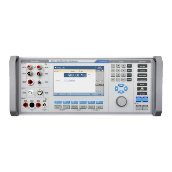
Advancing from previous M14x calibrator series, 9010 can now calibrate even 400 MHz scopes, 1.5 kV insulation testers and 1 MW power meters. On the other hand we kept all the popular functions including complete transducer and external sensor calibration (strain gauge, pressure, torsion, force, etc.) using... -
Page 7: Figure 2 Input/Output Terminals
9000-60 adapter is used for measurement of RTDs and 4W resistance in METER function (option MER), 91 adapter is used for cold junction compensation of thermocouples. Adapter terminals are described on the adapters themselves. Meatest 9010 User Manual... -
Page 8: Figure 3 Display
8. Input status. Indicates meter status (grey means disconnected, green means measuring) and shows diagram of active input terminals. 9. Meter reading. Meter function can be changed using FUNC button in METER group. Meatest 9010 User Manual... -
Page 9: Figure 4 Softkeys And Menu Buttons
Values can be edited with cursor keys and rotary knob as well. Use ⊳ and buttons to shift through digits and buttons to increment or decrement that digit. Knob rotation works as either or ⊳ / buttons, knob push toggles between the two modes. Meatest 9010 User Manual... -
Page 10: Rear Panel Overview
- ISO17025 calibration certificate - 3, 4 or 5-year extended warranty 9010 Multifunction calibrator can be ordered with integrated options as listed in Table 1. Integrated options can be fitted only by manufacturer and certified service providers. Meatest 9010 User Manual... -
Page 11: Remote Control
LAN communication uses Telnet protocol. Default log-in for Telnet client is “9010_SNxxxxxx 23”, where “xxxxxx” stands for serial number and 23 is default communication port. 1.4.2. SCPI commands and protocol See 9010 SCPI manual for complete SCPI reference, more details on communication setup and troubleshooting. Meatest 9010 User Manual... -
Page 12: Getting Started
- Use test leads rated for at least 1000 V and 20 A in all core functions and at least 2000 V in HVR high voltage resistance function. - Keep hands away from all Product terminals and exposed metal cable parts during operation. High voltage on those may be cause death or serious injury. Meatest 9010 User Manual... -
Page 13: Power On And Warm-Up
By default the Startup preset is set to VDC function, 10 V with output switched off. Warm-up Specified parameters are guaranteed 30 minutes after switching the calibrator on and stabilizing it in reference conditions. Figure 8 Factory default screen Meatest 9010 User Manual... -
Page 14: Function Setup
With MER option installed you can also take advantage of integrated multimeter and its measurement capabilities. Meter input can be activated and deactivated by pushing FUNC button. Similarly to calibrator output, meter input state is indicated by LED light in FUNC button and green rectangle next to Meter label. Meatest 9010 User Manual... -
Page 15: Menu Reference
- Current date to last calibration date plus calibration interval, see menu - Device status item Calibration for more details. - Testing tools Display and keyboard diagnostics - Modules List of internal electronic modules and their status Meatest 9010 User Manual... -
Page 16: Device Menu
> Subnet mask IPv4 format; locked with DHCP On 255.255.255.000 > Default gateway IPv4 format; locked with DHCP On 255.255.255.255 > Port number 0 – 9999 > Host name 14 alphanumeric characters; locked with DHCP Off M160_SN710011 Meatest 9010 User Manual... -
Page 17: Calibration Menu
Calibration menu Calibration menu contains internal calibration constants and other tools for device adjustment and is therefore password protected. See chapter 6 for more details on 9010 adjustment. Calibration menu has following items: 1. Data. Contains current calibration data. Structure of this menu is described in chapter 6.1. -
Page 18: Calibration Examples
- Triangle symmetrical - Ramp Up - Ramp Down - Harmonic adjustable harmonic products To select requested waveform push the soft key SHAPE, highlight requested item using softkeys cursor keys or rotary button and confirm with ENTER. Meatest 9010 User Manual... -
Page 19: Figure 14 Harmonic Products Setting
Push the soft key Bar to display relative level of harmonic products setting in frequency domain. Fundamental component is displayed in yellow, higher harmonics in red colour. Push the soft key PREWIEV to see the signal waveform in time domain. Figure 15 Signal preview Meatest 9010 User Manual... -
Page 20: Figure 16 List Of Preset Waveforms
See specification for detailed differences. Push SELECT key until field Output mode is not activated. Change setting from Active to Passive using soft key arrow keys, soft key List or rotary knob. Meatest 9010 User Manual... -
Page 21: Figure 17 Voltage Setup Screen
(available for Power line / BNC / External Master) - Voltage range Auto/20mV/200mV/2V/100V/280V/1000V In AUTO setting internal ranges are automatically switched to offer the lowest uncertainty. Any internal range 20 mV to 1000 V can be fixed. Meatest 9010 User Manual... -
Page 22: Ac/Dc Current
- Triangle symmetrical - Ramp Up - Ramp Down - Harmonic adjustable harmonic products To select requested waveform push the soft key SHAPE, highlight requested item using softkeys cursor keys or rotary button and confirm with ENTER. Meatest 9010 User Manual... -
Page 23: Figure 19 Current Setup Screen
External Master rear panel BNC Master connector synchronization - Current range Auto/200µA/2mA/20mA/200mA/2A/20A In AUTO setting internal ranges are automatically switched to offer the lowest uncertainty. Any internal range 200 µA to 30 A can be fixed. Meatest 9010 User Manual... -
Page 24: Resistance
20V PK SCOPE 10V PK 1 00V PK 2 V PK OPER STBY METER METER FUNC NULL 25V PK 10V PK 50V PK MAX 50 V PK MAX SELECT SETUP SYSTEM Figure 20 Two-wire resistance calibration Meatest 9010 User Manual... -
Page 25: Figure 21 Four-Wire Resistance Calibration
Selection of individual fix value positions can be done using softkeys , or cursor keys or using rotary button. Numerical keypad is not active in this mode. Calibration value is displayed on the display. Meatest 9010 User Manual... -
Page 26: Figure 22 High Resistance Calibration
Figure 22 High resistance calibration 4.3.4. Resistance SETUP Resistance SETUP can be activated using SETUP SOURCE key. Following parameters are available: - Terminal ground On/Off LO output terminals is internally connected to PE wire when parameter is set to ON. Meatest 9010 User Manual... -
Page 27: Capacitance
Numerical keypad is not active in this mode. 4.4.3. Capacitance SETUP Capacitance SETUP can be activated using SETUP SOURCE key. Following parameters are available: - Terminal ground LO output terminals is internally connected to PE wire when parameter is set to ON. Meatest 9010 User Manual... -
Page 28: Electric Power Meters, Analyzers And Energy Meters
20V PK SCOPE 10V PK 1 00V PK 2 V PK OPER STBY METER METER FUNC NULL 10V PK 25V PK 50V PK MAX 50 V PK MAX SELECT SETUP SYSTEM Figure 25 Power meter calibration Meatest 9010 User Manual... -
Page 29: Figure 26 Harmonic Mode
Figure 27 Energy mode Set requested time for which output signals should be connected to the output terminals. Use SELECT soft key to move active window. Both SIN and Harmonic mode can be applied in Energy mode. Meatest 9010 User Manual... -
Page 30: Figure 28 Power/Energy Soft Keys
+I/-I instead of current Current mode Normal: +I/-I terminals are used directly for current output Voltage from current: +I/-I terminals are used as second voltage output Coil: +I/-I terminals are used for external current coil connection Meatest 9010 User Manual... -
Page 31: Sco Scope Extension
Table 2 Scope option modes Select SCOPE function using SCOPE key, following screen will appear: Figure 30 Scope option Push the SCOPE key repeatedly to swap between Voltage – SINE – PWM – Time marker mode. Meatest 9010 User Manual... - Page 32 Push the OPER key to connect signal to the output terminals. Indicated pulse width is calculated by formula Δ = 1/f * R/100 [s], where f is frequency of output signal and R is duty cycle ratio in %. Meatest 9010 User Manual...
-
Page 33: Figure 31 Sco Option Device/Setup Menu
SOURCE on the display using labels „LOW Z“ and „50 Ω“. Amplitude unit Last item in the SETUP menu is selection of displayed units. Change of unit can be performed also in individual subfunctions using soft key Ampl. Unit. Meatest 9010 User Manual... -
Page 34: Temperature Sensor Simulation
Coefficients of „PT User“ scale. RTD calculation formula is = R0 * (1 + T*(A + T*(B + T*C(T-100.0)))) , where T is temperature in °C and R0 is nominal resistance of temperature sensor at 0 °C. Meatest 9010 User Manual... -
Page 35: Figure 33 Tc Temperature Sensor Simulation
SOURCE SETUP. It contains following items: - Temperature unit selection, °C, °F or K - Terminal ground, enables internally LO output terminal grounding - Output mode either passive (more accurate) or active (higher current available) Meatest 9010 User Manual... -
Page 36: Mer Multimeter Extension
Adapter 91 as follows: Figure 36 Thermocouple output through 91 Adapter 2. Select requested function. Use SELECT arrows key and rotary button or cursor keys. 3. Multimeter starts measuring of the input signal. Meatest 9010 User Manual... -
Page 37: Figure 37 Multimeter Softkeys
- Custom unit and Custom unit label. Custom unit with length up to 4 alphanumerical characters can be defined. Use navigation buttons or rotary knob to enter requested letters, switch between uppercase and lowercase using A ↔ a softkey and enable this feature by turning Custom unit ON. Meatest 9010 User Manual... -
Page 38: Figure 39 Meter Statistics Function
Indication of reading versus limits is displayed in METER field using LIMT label with arrows showing if the reading is below, inside or up. The LIMITS function is applicable in all multimeter functions. Figure 40 Meter limits function Meatest 9010 User Manual... -
Page 39: Table 3 Multimeter Setup
Statistics and Limits. The mathematic functions which have been switch on have indication with yellow bar in soft key description in the bottom line. label is simultaneously displayed in METER field showing that mathematic function has been applied. Meatest 9010 User Manual... -
Page 40: Performance Verification
1. Place the calibrator to the standard condition and let it switched on for at least one hour in a laboratory in reference conditions 22 °C to 24 °C. 2. Set Terminal ground item in 9010’s SOURCE SETUP menu to ON in order to suppress mains noise during measurement. -
Page 41: Test Points
19.0059 89.972 90.027 199.928 200.072 1000 749.63 750.37 99.93 100.07 µA 0.99962 1.00038 1.89936 1.90063 9.9979 10.0021 18.9965 19.0034 DC Current 99.979 100.021 8½ digit DMM 189.965 190.034 0.99967 1.00033 1.89949 1.90051 9.9955 10.0045 18.9932 19.0067 Meatest 9010 User Manual... - Page 42 Variable 8½ digit DMM Resistance LVR 99.9897 100.0103 kΩ 299.967 300.033 kΩ 0.99984 1.00015 MΩ 2.99952 3.00048 MΩ 9.9979 10.002 MΩ 29.9697 30.0303 MΩ 99.7997 100.2003 MΩ 299.099 300.9 MΩ 1000 1000 992.999 1007.001 MΩ Meatest 9010 User Manual...
-
Page 43: Table 4 List Of Main Test Points
-0.035nF +0.035nF 1 kHz Capacitance -0.25nF +0.25nF (min and max LCR meter relative to -0.0025µF +0.0025µF µF calibration 300 Hz -0.035µF +0.035µF µF values) -0.8µF +0.8µF µF 120 Hz Table 4 List of main test points Meatest 9010 User Manual... -
Page 44: Table 5 List Of Options' Test Points
COM/I- terminals. Current 19.9962 20.0038 Set source to Voltage AC, 1 V, 1 kHz. Connect Hi to V and Lo to COM terminals on 9010. Frequency 0.99995 1.00005 Use standard counter to measure frequency at Hi/Lo terminals. -
Page 45: Adjustment
6. Adjustment Adjustment is done through MENU > Calibration > Data. This menu item is password protected, default factory set calibration code is “9010”. Figure 41 Password entry Calibration menu structure Calibration data are sorted in a tree structure with following hierarchy: 1. -
Page 46: Calibration Point Adjustment
Calibration point adjustment Two different approaches to calibration value adjustment are applied in 9010: - Values denoted in % or without any unit (mostly used in source functions with continuous ranges like V function in fig. -
Page 47: List Of Calibration Points
-190.000 mA 0.000 00 A 0.000 00 A +1.900 00 A -1.900 00 A 20 A 0.000 0 A 0.000 0 A +19.000 0 A -19.000 0 A Table 6 Calibration points – DC voltage and current Meatest 9010 User Manual... -
Page 48: Table 7 Calibration Points - Ac Voltage And Current
190 µA 1.9 mA 20 mA 1.9 mA 19 mA Current Harmonic 200 mA 19 mA 190 mA 190 mA 1.9 A 20 A 1.9 A 19 A Table 7 Calibration points – AC voltage and current Meatest 9010 User Manual... -
Page 49: Table 8 Calibration Points - Resistance
11 mF 90 mF Measured at 1 kHz up to 33 nF, at 120 Hz between 100 nF and 100 µF. Values from 1 mF up are measured using ramp method. Table 9 Calibration points – Capacitance Meatest 9010 User Manual... -
Page 50: Table 10 Calibration Points - Hvr Option
1.000 00 kΩ Resistance 20 kΩ 0.000 0 kΩ 10.000 0 kΩ Frequency 1 kHz 1.000 00 kHz 1100 V (R<1MΩ) 900 V HVR option meter 1500 V (R>1MΩ) 900 V Table 12 Calibration points – MER option Meatest 9010 User Manual... -
Page 51: Maintenance
Fuse replacement 9010 calibrator has 2 user-replaceable fuses, both located on rear panel. Replace the fuses as follows: 1. Switch the calibrator off and disconnect power cord from it 2. Locate the fuse to be replaced: Mains fuse is in fuse/voltage selector case next to mains connector, current output fuse is in the middle of the rear panel. -
Page 52: Error Messages
Service Center. 7021: Source function is unavailable. Ask Meatest for possible upgrades. 7022: Meter function is unavailable. Ask Meatest for MER option upgrade. 7100-7999 Protective element has been triggered and output/input has been shut off in order to prevent calibrator damage. -
Page 53: Specifications
Safety class I according to IEC 61010 ed. 2 ESD class I according to EN 61326 Overvoltage CAT II Pollution Degree 2 Dimensions (W x H x D): 435 x 175 x 620 mm Weight: 24 kg (basic version) Meatest 9010 User Manual... -
Page 54: Voltage
+ 12 mV + 50 mV + 50 mV 280.000 – 1050.000 V + 85 mV + 85 mV Frequency is limited to 15 – 10000 Hz above 200 V. Frequency is limited to 20 – 1000 Hz. Meatest 9010 User Manual... - Page 55 THD 13.45 %, harmonics Current range: 1.00000 mV – 200.0000 V Frequency range: 15.000 – 1000.00 Hz Peak value uncertainty: 0.3 % of range + 50 µV Meatest 9010 User Manual...
-
Page 56: Current
+ 100 µA + 140 µA + 140 µA 1800 2000 0.200000 – 2.00000 A + 200 µA + 200 µA + 500 µA + 500 µA 1000 2.00000 – 20.00000 A + 6 mA + 6 mA Meatest 9010 User Manual... - Page 57 500 + 1 mV 220 Ω 8.2.2. Current coil (option 140-50) Applicable multiplier: 2 – 200 Max. simulated current: multiplier ∙ 20 A (1000 A with 140-50 Current Coil) Frequency range: 45 – 65 Hz Additional uncertainty: 0.25 % Meatest 9010 User Manual...
-
Page 58: Resistance
6200 + 1 kΩ 7000 + 1 kΩ 4 – 20 nA Range boundaries are based on calibration values of fixed resistance mode standards and as such may deviate from nominal values by up to 5%. Meatest 9010 User Manual... - Page 59 0.5 % + 5 V 1.0000 – 1.9999 GΩ 1500 V 1 % + 5 V 2.000 – 10.000 GΩ 1500 V 1 % + 5 V 100 GΩ 1500 V 1.5 % + 5 V Meatest 9010 User Manual...
-
Page 60: Capacitance
1000 Hz 10.00000 nF 0.35 % 1000 Hz 100.0000 nF 0.25 % 500 Hz 1.000000 µF 0.25 % 300 Hz 10.00000 µF 0.35 % 300 Hz 100 mA 100.0000 µF 0.8 % 300 Hz 100 mA Meatest 9010 User Manual... -
Page 61: Power And Energy
= [1 – sin (φ + dφ) / sin (φ)] ∙ 100 for reactive power dPF = 0 for apparent power where: - ϕ is set phase shift between voltage and current - dϕ is uncertainty of set phase shift Meatest 9010 User Manual... - Page 62 - dt = 0.01 % + 0.3 s = 0.11 % of 5 minute period AC energy uncertainty is then calculated as dE = √ ( 0.035 + 0.08 + 0.0003 + 0.11 + 0.03 ) = 0.14 % Meatest 9010 User Manual...
-
Page 63: Harmonics
: 200 Ω Pt385 0.04 0.04 0.05 0.08 0.12 0.15 : 500 Ω Pt385 0.03 0.04 0.05 0.09 0.11 0.14 : 1000 Ω Type -80 – 0 0 – 100 100 – 260 Ni 120 0.05 0.08 0.14 Meatest 9010 User Manual... - Page 64 0 – 100 100 – 280 280 – 1830 1830 – 2315 uncertainty 0.45 0.37 0.34 0.47 range 100 – 200 200 – 430 430 – 2080 2080 – 2315 uncertainty 0.72 0.49 0.35 0.39 Meatest 9010 User Manual...
-
Page 65: Sco 400 Mhz Scope Option
25 ppm Amplitude range: 0.000 mV – 200.00 V Square wave: 1.000 mV – 200.00 V Amplitude uncertainty: as per DCV specifications Square wave: 0.3 % + 50 µV Max. load current: as per ACV specifications Meatest 9010 User Manual... - Page 66 PWM square wave above 400 ns Time period range: 2.50000 ns – 10.000 s Time period uncertainty: 2.5 ppm Amplitudes: 50, 100, 500 and 1000 mV / 50 Ω Jitter: < 2 ns Rise time: < 1 ns Meatest 9010 User Manual...
-
Page 67: Mer Integrated Multimeter Option
: 200 Ω Pt385 0.08 0.08 0.10 0.16 0.24 0.30 : 500 Ω Pt385 0.08 0.08 0.10 0.18 0.22 0.28 : 1000 Ω Type -80 – 0 0 – 100 100 – 260 Ni 120 0.15 0.24 0.42 Meatest 9010 User Manual... - Page 68 0 – 100 100 – 280 280 – 1830 1830 – 2315 uncertainty 0.46 0.38 0.63 0.94 range 100 – 200 200 – 430 430 – 2080 2080 – 2315 uncertainty 1.00 0.67 0.46 0.51 Meatest 9010 User Manual...
-
Page 69: Certificate Of Conformity
Certificate of conformity MEATEST, spol. s r. o., manufacturer of 9010 Multifunction Calibrator, based in Železná 3, 619 00 Brno, Czech Republic, declares that its product conforms to following specifications: Safety requirements - EN 61010-1 ed. 2:2011 + A1:2019 Electromagnetic compatibility - EN 61000 part 3-2 ed.
Need help?
Do you have a question about the 9010 and is the answer not in the manual?
Questions and answers