Table of Contents
Advertisement
Quick Links
Advertisement
Table of Contents

Related Manuals for Meatest M-140


Summary of Contents for Meatest M-140
- Page 1 M-140 Multifunction Calibrator Operation manual...
-
Page 3: Table Of Contents
MEATEST M-140 Multifunction Calibrator Content Operation manual ........................1 Basic Information ........................3 Preparation for operation ......................4 Inspecting package contents, selecting the installation location .............5 Power-on ..............................5 Warm-up time .............................5 Replacement of fuse ..........................6 Safety precautions..........................6 Description of controls ......................7 Front panel ............................7... - Page 4 M-140 Multifunction Calibrator MEATEST Tester ............................45 Basic menu ............................45 Execution of test program ....................... 45 Programming the test ........................46 Setting the type of signals and the number of steps ..................47 Setting the numeric values of the test ......................47 Setting the relays............................
-
Page 5: Operation Manual
It generates fixed non-harmonic signals to allow calibration of measuring instruments using signals with non-zero harmonic distortion. Frequency, amplitude and duty cycle of output signal can be adjusted. M-140 Multifunction Calibrator is also suitable for basic calibration of oscilloscopes. - Page 6 M-140 Multifunction Calibrator MEATEST ATTENTION ! The calibrator generates life-threatening high voltage. The calibrator can only be used in line with this Manual. Operation manual v46...
-
Page 7: Preparation For Operation
MEATEST M-140 Multifunction Calibrator Preparation for operation Inspecting package contents, selecting the installation location Basic package includes the following items: • Multifunction calibrator • Power cord • Spare fuse T4L250/T, T8L250/T • Operation manual. • Test report • Test cable 1000V/20 A 2 pcs •... -
Page 8: Replacement Of Fuse
M-140 Multifunction Calibrator MEATEST Replacement of fuse The calibrator includes a fuse located in the mains connector at the rear panel. Replace the fuse as follows: • Switch off the calibrator • Remove the end of power cord from the mains connector at the rear panel. -
Page 9: Description Of Controls
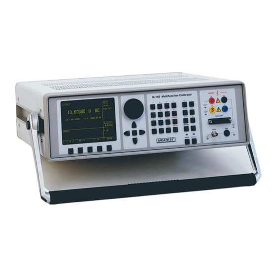
MEATEST M-140 Multifunction Calibrator Description of controls Front panel The front panel of the calibrator includes a flat luminiscent display, control buttons and output terminals. The following picture shows the control part of the front panel. Display buttons There are five buttons below the display, whose meaning changes depending on the contents of the display. These buttons usually call-up the MENU, allow range change, step, logging of values etc. - Page 10 M-140 Multifunction Calibrator MEATEST The function of the potentiometer can usually be performed by the cursor buttons. The central button is used to confirm the selection (ENTER). Numeric keyboard The keyboard allows the entry of numeric values on the display. The central button is used to confirm the selection (ENTER).
- Page 11 MEATEST M-140 Multifunction Calibrator Output / input terminals buttons OUTPUT button is used to connect the output signal of the calibrator to the output terminals. The connection is confirmed by red LED and a symbol at the display. METER button can be used to connect the input terminals to the internal multimeter. The connection is confirmed by green LED.
- Page 12 M-140 Multifunction Calibrator MEATEST Label Signal Limitation 0V5MER common terminal of multimetr power supply source ground (protection earth) SIMLI RC simulator output, current terminal Li Umax.= 10Vpp, Imax.=40mA SIMLU RC simulator output, voltage terminal Lu Umax.= 10Vpp, Imax.=40mA ground (protection earth)
- Page 13 MEATEST M-140 Multifunction Calibrator Display 1a 1b 1c 1d 1e 2a 2b 1g 1f The display is divided to three horizontal sections: OUTPUT section This section displays the set-up values of generated signals and the data related to the calibrator status. The...
- Page 14 M-140 Multifunction Calibrator MEATEST • cold junction temperature of TC sensors and the selected type of TC sensor • value of amplitude and shape type for frequency function Information section The information section located in the right part of the display displays additional information related to the selected function: •...
-
Page 15: Rear Panel
MEATEST M-140 Multifunction Calibrator Rear panel The rear panel of the calibrator includes ventilation holes, power cord socket with fuse, mains voltage selector, mains switch, IEEE 488 connectors for connection to GPIB bus and type plate with serial number. air inlet - forced ventilation... -
Page 16: Control Of The Calibrator
M-140 Multifunction Calibrator MEATEST Control of the calibrator Selection of function After the power is switched on and the initial checks complete, the calibrator resets to its reference status, i.e. DC voltage output with set value of 10 V and output terminals disconnected. Internal multimeter is switched off. The... - Page 17 MEATEST M-140 Multifunction Calibrator Entry of the value using cursor buttons • press , , or button. The display now includes cursor marks which point to the active digit. • and buttons can be used to change the active digit. , buttons can be used to change the position of the cursor marks •...
-
Page 18: Setting Relative Deviation
M-140 Multifunction Calibrator MEATEST Setting relative deviation All function modes of the calibrator except frequency mode allow a relative deviation of output value from the main data to be set using a separate display. Relative deviation is displayed in the “minor data” section of the display and is designated with „... -
Page 19: Change Of Value By Factor Of Ten
MEATEST M-140 Multifunction Calibrator Setting relative deviation using potentiometer • keep pressing the center cursor button until [ _ _ _ _ _ _ _ ] symbols appear under the relative deviation value in the “minor data” section of the display •... -
Page 20: Setting The Frequency
M-140 Multifunction Calibrator MEATEST If voltage over 100 V is set in the voltage mode, special algorithm must be followed to connect the output terminals. The algorithm is described in the „Generation of calibrated voltage“ chapter of this Manual. Setting the frequency Frequency can only be selected in AC voltage (ACV) mode, AC current (ACI) mode , power (P-E) mode and frequency (f) mode. -
Page 21: Generation Of Calibrated Voltage
MEATEST M-140 Multifunction Calibrator If frequency larger or smaller than the calibrator’s range is entered, the calibrator displays an error message: „Value is too large (small)“. Generation of calibrated voltage The multifunction calibrator provides calibrated DC and AC voltage. Output terminals for voltage ranges are labeled “... - Page 22 M-140 Multifunction Calibrator MEATEST Control sequence when output voltage over 100 V is selected When output voltage over 100 V is selected, the information section of the display shows the symbol which informs that a life-threatening voltage will be present at the output terminals. If the output terminals are currently connected, they will be disconnected when output voltage over 100 V is selected.
-
Page 23: Generation Of Calibrated Current
MEATEST M-140 Multifunction Calibrator Generation of calibrated current The multifunction calibrator provides calibrated DC and AC current. Output terminals for voltage ranges are labeled “ +I “ and “ -I “ at the front panel. The terminals can carry high current and are the only terminals to which the calibrated object can be connected. -
Page 24: Generation Of Non-Harmonic Shapes
M-140 Multifunction Calibrator MEATEST Overloading the terminals When external circuit connected to current output terminals is disconnected or there is higher voltage at the load than permitted, the calibrator disconnects the output terminals and displays „Overload I output“ message. The same message can be displayed when 50-turn coil is used for AC current output at frequencies above 80 Hz. -
Page 25: Simulation Of Resistance And Capacitance
MEATEST M-140 Multifunction Calibrator • below the main data, an information about the shape type „Shape xxxxx“ is displayed. • below the main data, calculated effective value of the output signal is displayed. • for squarewave signals, set value of duty cycle „PWM= xx %“ is displayed. - Page 26 M-140 Multifunction Calibrator MEATEST • Set desired value of resistance (capacitance) or relative deviation. The value can be set using numeric keyboard, potentiometer or cursor buttons. Simulated resistance (capacitance) is not yet connected to the output terminals. The information section of the display shows the symbol which...
- Page 27 MEATEST M-140 Multifunction Calibrator Frequency dependence of resistance and capacitance Electronic simulator of resistance can be used with DC and AC test signal. Electronic simulator of capacitance can be used in AC range from 20 Hz to 1000 Hz. Operation manual v46...
-
Page 28: Generation Of Electric Power And Energy
M-140 Multifunction Calibrator MEATEST Generation of electric power and energy The multifunction calibrator can generate exact value of electric power and energy. P-E function provides output voltage at Hi - Lo terminals and output current at +I - -I terminals. Lo and -I terminals are electrically connected. - Page 29 MEATEST M-140 Multifunction Calibrator The calibrator can display AC power in one of three ways: • apparent power in VA • active power in W • reactive power in VAr Keep pressing MODE display button to change the function mode. Along with mode change, the power display (depending on set power factor) and unit of measurement change as well.
- Page 30 M-140 Multifunction Calibrator MEATEST Setting the voltage • The main power value can be changed by changing the voltage. • Select P-E mode and then keep pressing the center cursor button until [ _ _ _ _ _ _ _ ] symbols appear under the voltage (U = xxx.xxxx V).
- Page 31 MEATEST M-140 Multifunction Calibrator Setting the power factor (AC power only) • If W or Var is indicated, the main power value can be changed by changing the power factor. Change of power factor does not change the output apparent power.
- Page 32 When calibrating the power and energy meters with separate voltage and current circuits, it is advisable to select GND U ON and GND I ON (both grounding methods on) on the M-140 calibrator. This setting will ground both the current and voltage output of the calibrator.
-
Page 33: Generation Of Frequency
MEATEST M-140 Multifunction Calibrator Uncertainty of set power displayed on the Accuracy line of the display is calculated according to the following formula: d P = ( dU for active power + dI + dPF + 0.03 ) [%] d P = ... - Page 34 M-140 Multifunction Calibrator MEATEST • Set the frequency using numeric keyboard, cursor buttons or potentiometer. Output signal is not yet connected to the output terminals. The information section of the display shows the symbol which informs about the disconnection of output terminals...
- Page 35 MEATEST M-140 Multifunction Calibrator Setting the attenuation Signal attenuation in dB can only be set in HF mode. Attenuation can be set in steps of (0, -10, -20, -30) dB. • Select the frequency mode and keep pressing the center cursor button until [ _ _ _ _ _ _ _ ] symbols appear under the attenuation value (a = x.xxx dB).
-
Page 36: Simulation Of Temperature Sensors
M-140 Multifunction Calibrator MEATEST Setting the duty cycle Duty cycle can only be set in PWM mode. • Select the frequency mode and keep pressing the center cursor button until [ _ _ _ _ _ _ _ ] symbols appear under the duty cycle value (PWM = xx %). - Page 37 MEATEST M-140 Multifunction Calibrator resistance temperature sensors: Pt 1.385, Pt 1.392, Ni resistance at 0 C labeled R0 (resistance temperature sensors only) cold junction temperature of thermocouple sensors labeled RJ set value of relate deviation in %, labeled T = xxxx.x °C (K)
- Page 38 M-140 Multifunction Calibrator MEATEST Entry of R0 coefficient for resistance temperature sensors C labeled R0 can be set. The range is 20 to 2k for all types For resistance temperature sensors, resistance at 0 of resistance temperature sensors. •...
- Page 39 MEATEST M-140 Multifunction Calibrator Automatic compensation of cold junction temperature Automatic cold junction TC sensors compensation can be performed, when cable adapter Option 140-01 is used for simulating. Ambient temperature measured by in cable adapter mounted Pt1000 sensor is taken as temperature of cold junction.
-
Page 40: Multimeter
M-140 Multifunction Calibrator MEATEST Multimeter The calibrator includes a built-in multimeter which can measure many electrical and non-electrical values. Besides DC voltage and current, it can measure frequency, temperature and when external strain gauge sensors is connected, even other non-electrical values can be measured. The multimeter can only be connected through AUXILIARY connector. -
Page 41: Function Selection
MEATEST M-140 Multifunction Calibrator When the multimeter is being set-up, measurement cannot be initiated. Measurement can only be initiated after the menu is left using the INPUT button. Function selection • Press METER direct control button and select FUNCTION option from the menu using cursor buttons. -
Page 42: Use Of Calculation Formula
M-140 Multifunction Calibrator MEATEST • Press the knob of the potentiometer to complete the setting. • After the unit of measurement is selected, use or cursor buttons to move onto the next menu option. The same can be achieved using the potentiometer after pressing the knob. Press EXIT display button the close the range selection menu and to return to the basic display. -
Page 43: Setting Function Parameters
MEATEST M-140 Multifunction Calibrator • After setting the coefficients, use or cursor buttons to switch to the previous or next menu option. The same can be achieved using the potentiometer after pressing the knob. Press EXIT display button the close the range selection menu and to return to the basic display. -
Page 44: Start Of Measurement
M-140 Multifunction Calibrator MEATEST Start of measurement To start a measurement: • Press INPUT direct control button in the basic state of the calibrator. • INPUT field on the display shows the measured value. The measurement is indicated by a green LED above the INPUT button. - Page 45 MEATEST M-140 Multifunction Calibrator Zeroing function can be used e.g. to compensate the voltage drops at the cables, to suppress any remanent value of the signal etc. Overloading can damage the multimeter. Notes: The current inputs of the multimeter are protected from current overloading by a fuse located in 140-41 cable adapter.
-
Page 46: Simultaneous Functions
M-140 Multifunction Calibrator MEATEST Simultaneous functions The multifunction calibrator allows simultaneous generation of calibrated signal along with measurement of another signal using the built-in multimeter. To use both parts of the calibrator simultaneously, cable adapters supplied by the manufacturer are necessary. -
Page 47: Tester
MEATEST M-140 Multifunction Calibrator Tester The calibrator includes an application SW, which facilitates automated testing of regulators and transducers. Tester function combines the use of the calibrator as the source of precision signal with automatic change of output signal, while the response of the unit being tested is measured by the calibrator’s built-in multimeter. The calibrator is capable of subsequent processing of measured values, providing PASS/FAIL indication. -
Page 48: Programming The Test
M-140 Multifunction Calibrator MEATEST After the test program concludes, the calibrator displays a table showing the results. The table includes the sequence number of each step, set output value of the calibrator, the value measured by the multimeter and the result of the respective test step (PASS/FAIL). -
Page 49: Setting The Type Of Signals And The Number Of Steps
MEATEST M-140 Multifunction Calibrator Setting the type of signals and the number of steps Type of output signal can be set using OUTPUT display button. Press the button repeatedly to select the signal which will be generated at the output terminals after the test program is executed. The following options are available: VDC –... -
Page 50: Setting The Relays
M-140 Multifunction Calibrator MEATEST • Select the value to be changed by cursor buttons or the knob of the potentiometer. • Enter the numeric value using the units of measurement displayed in the header of the table. • Confirm the entry by pressing ENTER. New entry is copied to the respective position. -
Page 51: Setup Menu
MEATEST M-140 Multifunction Calibrator Setup menu The multifunction calibrator allows many other, less frequently used parameters to be set. Setup menu is used to set these parameters. Setup menu is opened by pressing SETUP display button. If output terminals are connected, they will be disconnected and the following display appears: Use ... - Page 52 M-140 Multifunction Calibrator MEATEST If neither the calibrator’s output, nor the meter’s inputs are grounded, signal/noise ratio can arise at the calibrator’s output. Temp.scale ..xx ITS90/PTS68 This parameter allows the temperature scale for platinum resistance temperature sensors to be selected. Pressing the display buttons allows to switch between ITS90 and PTS68 temperature scales.
- Page 53 MEATEST M-140 Multifunction Calibrator 13. Keyb.beep ..xx ON/OFF This parameter allows the acoustic indication of pressed buttons to be switched off or on. ON and OFF display buttons can be used to switch the indication off or on. ON is set by the manufacturer.
- Page 54 M-140 Multifunction Calibrator MEATEST The purpose of the calibration code is to prevent unauthorized users from changing the calibration of the instrument. Note It is advisable to write down actual calibration code if changed. If you forget the calibration code, you have to send the calibrator to the manufacturer.
-
Page 55: Calibration Mode
MEATEST M-140 Multifunction Calibrator Calibration mode The multifunction calibrator includes a calibration procedure, which allows calibration of the calibrator. Zero point and slope of the characteristics of individual generation and measurement ranges are set during the calibration in predefined order. The calibration can only be controlled using the buttons and menu on the calibrator. - Page 56 M-140 Multifunction Calibrator MEATEST the squarewave output signal depends on the frequency accuracy and cannot be calibrated, it can only be checked. The respective check is not included in the calibration procedure. Multimeter is calibrated on voltage ranges 20mV, 200mV, 2 V and 10 VDC voltage ranges, current range 20 mADC and on resistance range 2000 .
- Page 57 MEATEST M-140 Multifunction Calibrator • Use and cursor buttons to move the cursor through the list: VOLTAGE DC All DC voltage ranges calibration VOLTAGE AC All AC voltage ranges calibration CURRENT DC All DC current ranges calibration CURRENT AC...
- Page 58 M-140 Multifunction Calibrator MEATEST Display buttons have the following meaning: WRITE new calibration value is entered into the memory, old value is irreversibly lost SKIP current calibration step is skipped, old value is retained in the memory EXIT current calibration is terminated. After this button is pressed, the calibration memory hold all data (old or new entered) and the calibrator returns to the calibration menu.
- Page 59 MEATEST M-140 Multifunction Calibrator Press “EXIT” display button to terminate the calibration. After the button is pressed, the calibration date is saved internally and the calibrator returns to the state it was in before the calibration has been started. Calibration points Each function of the calibrator has assigned fixed calibration points which have to be set during the calibration.
- Page 60 M-140 Multifunction Calibrator MEATEST VOLTAGE DC function nominal value [V] set limits [V] range [V] note 20 m zero calibration -20 m zero calibration 19 m 20 m slope calibration -19 m -20 m slope calibration 200 m zero calibration...
- Page 61 MEATEST M-140 Multifunction Calibrator CURRENT DC function nominal value [A] set limits [A] range [A] note 200 u zero calibration -200 u zero calibration 190 u 200 u slope calibration 190 u -200 u slope calibration 20 n zero calibration...
- Page 62 M-140 Multifunction Calibrator MEATEST POWER DC function DC current calibration nominal value [A] set limits [A] range [A] note 400 n 20 m zero calibration 400 n -20 m zero calibration 19 m 20 m slope calibration -19m -20 m...
- Page 63 MEATEST M-140 Multifunction Calibrator RESISTANCE function nominal value [ set limits [ range [ 10 – 50 0.01 10 – 50 0.005 10 – 50 0.005 0.005 50 - 100 0.005 50 - 100 0.01 50 - 100 100 –...
- Page 64 M-140 Multifunction Calibrator MEATEST CAPACITANCE function nominal value [F] set limits [F] range [F] 900 p – 2.5 n 900 p – 2.5 n 900 p 900 p – 2.5 n 2.5 n 5 n - 10 n 2.5 n...
-
Page 65: Calibration Procedure
Select VOLTAGE DC from the calibration menu and confirm by pressing SELECT button. Switch M-140 output terminals ON. Follow the instructions provided on the calibrator’s display and the DCV table to adjust the calibrator’s output in the calibration points. - Page 66 M-140 Multifunction Calibrator MEATEST To adjust the calibrator’s output in the calibration points, press SELECT button and use , , , cursor buttons or potentiometer to adjust the output voltage. Confirm correctly set value by pressing WRITE display button. If you want to skip the calibration point whose calibration you have already entered, press SKIP display button.
- Page 67 MEATEST M-140 Multifunction Calibrator Follow the instructions provided on the calibrator’s display and the POWER DC table to adjust the calibrator’s output in the calibration points. To adjust the calibrator’s output in the calibration points, press SELECT button and use , , , ...
- Page 68 M-140 Multifunction Calibrator MEATEST Capacitance ranges calibration Capacitance ranges calibration is performed by both calibration methods, i.e. setting the checked value and measuring this value with the standard instrument, as well as setting the nominal value of the calibrator’s measurement range on the external multimeter by adjusting the calibrator’s output. If the entry of measured value to the calibrator is required, VALUE METER is displayed at the respective calibration point.
- Page 69 MEATEST M-140 Multifunction Calibrator Amplitude calibration in frequency mode Select FREQUENCY in the calibration menu. Connect the external multimeter with DC voltage measurement range selected to calibrator’s Hi - Lo output terminals. Follow the instructions provided on the calibrator’s display and the F table to adjust the calibrator’s output in the calibration points.
- Page 70 M-140 Multifunction Calibrator MEATEST • Leave input terminals of Option 40 adapter OPEN. • Make short on calibrator output terminals +I - -I. • Press SELECT display button to select the first calibration point, 0 mA. • After the value stabilizes, press WRITE display button to write new calibration zero value.
- Page 71 MEATEST M-140 Multifunction Calibrator • After the value stabilizes, write calibration value of resistance standard to the lower line and confirm by pressing WRITE. 20 mV voltage range calibration • Make short of test wires of Option 60 adapter. •...
- Page 72 M-140 Multifunction Calibrator MEATEST • Set such output voltage on the calibrator, that standard multimeter indicates 1900.0 mV • After the value stabilizes, press WRITE display button to write new calibration value. Terminals of the calibrator will switch OFF automatically.
-
Page 73: Error Messages
MEATEST M-140 Multifunction Calibrator Error messages If an error occurs during the calibrator’s operation or control, error message is displayed on the display. Errors can be caused by: • incorrect control using the front panel, i.e. attempts to force a prohibited mode, e.g. setting an out-of-range value, overloading of output terminals etc.,... - Page 74 M-140 Multifunction Calibrator MEATEST label description troubleshooting error Overload 2V ! 2V range overloaded Output current is too high. Increase load resistance. Overload 20V ! 20 V range overloaded Output current is too high. Increase load resistance. Overload 200V ! 200, 1000 V ranges Output current is too high.
-
Page 75: Functional Description Of The Calibrator
MEATEST M-140 Multifunction Calibrator Functional description of the calibrator Basic blocks Basic functional blocks are: • front panel keyboard • LCD display • output terminals • output voltage amplifier 200 V • output voltage amplifier 20 A • main board •... - Page 76 M-140 Multifunction Calibrator MEATEST Operation manual v46...
- Page 77 MEATEST M-140 Multifunction Calibrator 2, 20 V DC voltage ranges The functional scheme is shown in the picture below: There is a DC reference voltage source integrated within the 22bit measurement converter. Its output is fed to the output stage for 2 and 20 V range. Output voltage present at Hi and Lo terminals is sensed by sensing wires.
- Page 78 M-140 Multifunction Calibrator MEATEST The calibrator’s built-in generator generates a sine wave with voltage-controlled amplitude. The frequency is derived from microprocessor control circuit’s crystal oscillator. The signal is fed to 20 V or 200 V amplifier and then to output terminals. Feedback circuits sense the voltage present at the output terminals, normalize its value and detects it.
- Page 79 MEATEST M-140 Multifunction Calibrator Current converter The current converter and current amplifier form a separate design block based on a transconductivity converter with 10 S nominal conversion ratio. A six-range switched current amplifier connects to the output of the current converter.
- Page 80 M-140 Multifunction Calibrator MEATEST Frequency synthesizer Frequency synthesis circuitry allows fine setting of frequency in the whole calibrator’s range. Frequency synthesis uses DSP circuits with basic frequency 20 MHz. Power and energy mode In the power/energy mode, the calibrator supplies the set voltage to Hi-Lo terminals and the set current through +I –...
-
Page 81: Calibrator's Maintenance
MEATEST M-140 Multifunction Calibrator Calibrator’s maintenance The multifunction calibrator is electronic instrument with microprocessor control. All blocks which are heavily loaded during the operation are cooled by a fan. Rules for correct operation Especially the following rules should be adhered to guarantee correct operation of the calibrator: •... - Page 82 M-140 Multifunction Calibrator MEATEST • Replace the fuse holder, reconnect the power cord and switch on the calibrator. If the problem persists, contact the manufacturer. If an obvious fault is evidenced, e.g. a measurement range or an operating mode is not functional, the user cannot correct the fault.
-
Page 83: Verification Test
MEATEST M-140 Multifunction Calibrator Verification test Procedure recommended for verifying parameters of the calibrator is described in this chapter. During tests it is not necessary access to the interior of the instrument. Required equipment Following instruments are required for performance verification test: •... - Page 84 M-140 Multifunction Calibrator MEATEST Basic steps of the performance verification test Verification procedure consists of following steps: • 20 V DC voltage test with linearity check • DC voltage internal ranges 20 mV, 200 mV, 2 V, 240 V, 1000 V test •...
- Page 85 MEATEST M-140 Multifunction Calibrator 10. Perform AC/DC high current test on range 20 A according to the table VIII. Deviation should not exceed specified limit. 11. Connect standard powermeter to the appropriate output and current terminals of the calibrator. 12. Perform AC/DC power test according to the table IX. Deviations should not exceed specified limits.
- Page 86 M-140 Multifunction Calibrator MEATEST 29. Disconnect cable adapter Option 60 and connect distortion meter to the voltage output terminals of the calibrator. Set output voltage 10 VAC, frequency 1000 Hz and sin waveform. 30. Check harmonic distortion of output signal. It should not exceed 0.05%.
- Page 87 MEATEST M-140 Multifunction Calibrator Tables of limits 20 V DC Basic range with linearity test Function Range Value (V) Frequency (Hz) Deviation allowed(%value) V-DC 20.0 0.008 V-DC 20.0 0.006 V-DC 20.0 0.005 V-DC 20.0 0.004 V-DC 20.0 10.0 0.004 V-DC 20.0...
- Page 88 M-140 Multifunction Calibrator MEATEST AC voltage test Function Range Value (V) Frequency (Hz) Deviation allowed(%value) V-AC 20 mV 0.019 1000 0.358 V-AC 200 mV 0.19 1000 0.142 V-AC 1000 0.030 V-AC 20.0 19.0 0.030 V-AC 20.0 19.0 0.030 V-AC 20.0 19.0...
- Page 89 MEATEST M-140 Multifunction Calibrator AC current test Function Range Value (A) Frequency (Hz) Deviation allowed(%value) A-AC 200.0 uA 0.00019 0.161 A-AC 2.0 mA 0.0019 0.081 A-AC 20.0 mA 0.019 0.055 A-AC 20.0 mA 0.019 0.055 A-AC 20.0 mA 0.019 1000 0.055...
- Page 90 M-140 Multifunction Calibrator MEATEST Frequency test Function Range Value (Hz) Frequency (Hz) Deviation allowed(%value) FREQ 1 kHz 1000.0 0.005 Table XII Multimeter test Function Range Value (Hz) Frequency (Hz) Deviation allowed(%value) FREQ 1 kHz 1000.0 Hz 0.005 V-DC 10 V 10.0 V...
-
Page 91: System Control
MEATEST M-140 Multifunction Calibrator System control The calibrator includes standardized IEEE-488 bus and RS232 serial line. System connectors are located at the rear panel. For the remote control to work properly, bus parameters must be set in the system menu. For IEEE-488 bus, address is important (0 to 30 setting range). - Page 92 M-140 Multifunction Calibrator MEATEST All commands listed in this chapter are explained in two columns: KEYWORD and PARAMETERS. KEYWORD column includes the name of the command. Each command includes one or more keywords. If a keyword is in brackets ( [ ] ), it is not mandatory. Non-mandatory commands are used only to achieve compatibility with language standard SCPI.
- Page 93 MEATEST M-140 Multifunction Calibrator OUTP :ISEL (?) <CPD> { HIGH | HI50 } This command activates or deactivates the 1000A current range (using a 50-turn coil). • HIGH - deactivates the 50-turn coil • HI50 - activates the 50-turn coil (up to 1000A range) If query is sent, M140 returns HIGH if the 50-turn coil is deactivated or HI50 if it is activated.
- Page 94 M-140 Multifunction Calibrator MEATEST : AUXiliary (?) <CPD> { ON | OFF | 0 | 1 } : ADAPter (?) : FREQuency [: CW ] (?) <DNPD> : DUTY (?) <DNPD> : VOLT (?) <DNPD> : ATTE (?) <DNPD> : TEMPerature : UNITs (?) <CPD>...
- Page 95 MEATEST M-140 Multifunction Calibrator [SOUR] :VOLT [:LEVE] [:IMM] [:AMPL] (?) <DNPD> This command activates the generation of DC or AC voltage (depending on the DC or SIN parameter of the FUNC command). <DNPD> Represents the value of DC or AC voltage expressed in Volts. Negative value is accepted for DC voltage.
- Page 96 M-140 Multifunction Calibrator MEATEST <DNPD> Represents the phase shift between the output voltage and current in degrees (DEG setting), or specified as a value of the power factor (COS setting). “Technical Data” chapter lists the acceptable ranges. ,{LEAD|LAG} This parameter is entered only when specifying the value of the power factor. If the value is omitted, LAG is used.
- Page 97 MEATEST M-140 Multifunction Calibrator [SOUR] :AUX (?) <CPD> { ON | OFF | 0 | 1 } This command connects or disconnects the output signals to AUXILIARY connector. • ON or 1 - output signals are connected to AUXILIARY connector, front panel terminals are disconnected.
- Page 98 M-140 Multifunction Calibrator MEATEST [SOUR] :FREQ :VOLT (?) <DNPD> This command sets the amplitude of PWMP, PWMS, PWMN signals. Examples: To set the amplitude of PWMP digital frequency signal: FUNC :PWMP ; FREQ :VOLT <DNPD> <cr> <DNPD> Represents the voltage in Volts. 0.000 to 10.000 V can be set.
- Page 99 MEATEST M-140 Multifunction Calibrator [SOUR] :TEMP :THER :RJUN (?) <DNPD> This command sets the temperature of cold end of thermocouple. <DNPD> Represents the temperature expressed in the units set by the ‘UNIT’ command. “Technical Data” chapter lists the acceptable ranges.
- Page 100 M-140 Multifunction Calibrator MEATEST MEASure : CONFigure : VOLTage : CURRent : MVOLTage : RESistance : FREQuency : TEMPerature : RTD : TYPE (?) <CPD> { PT385 | PT392 } : NRESistance (?) <DNPD> : THERmocouple : TYPE (?) <CPD> { B | E | J | K | N | R | S | T } : RJUNction (?) <DNPD>...
- Page 101 MEATEST M-140 Multifunction Calibrator MEAS :CONF :RES This command selects the function RES (range 0 .. 2000) of internal multimeter and switches it on. Example: to set the multimeter to resistance measurement mode: MEAS :CONF :RES <cr> MEAS :CONF :FREQ This command selects the function FREQ of internal multimeter and switches it on.
- Page 102 M-140 Multifunction Calibrator MEATEST Example: to set the temperature of cold end of thermocouple to 25C: MEAS :CONF :TEMP :THER :RJUN 25 <cr> If query is sent, M140 returns the set temperature using standard exponential format. Example: 20.5C is returned as 2.050000e+001.
- Page 103 MEATEST M-140 Multifunction Calibrator *IDN? This command returns the identification of the manufacturer, model, serial number and firmware revision. The reply is formatted as follows: MEATEST,M-140,412341,4.6 Operation complete *OPC <cr> This command sets the OPC bit in the ESR (Event Status Register) when all pending operations are complete.
-
Page 104: Remote Control
M-140 Multifunction Calibrator MEATEST This command sets condition of the Service Request Enable register. Since bit 6 is not used, the maximum entry is 191. Service Request Enable reading (IEEE488 only) *SRE? <cr> This query returns the Service Request Enable Register. - Page 105 MEATEST M-140 Multifunction Calibrator This command locks out the local control; the calibrator cannot be returned to local control by pressing LOCAL button. Return to local control can only be performed by a command sent through the bus, or by switching the calibrator off and on.
-
Page 106: Standard Status Data Structures
M-140 Multifunction Calibrator MEATEST Standard Status Data Structures All status registers are defined by the IEEE-488.2 standard. The programmer has access to Status Register, Enable Register and Output Queue in the M140 Calibrator. Status data structure of M140 Calibrator contains following registers: STB –... - Page 107 MEATEST M-140 Multifunction Calibrator Request Service, bit 6. The RQS bit is set to 1 whenever bits ESB or MAV change from 0 to 1 and are enabled (1) in the SRE. When RQS is 1, the M140 asserts the SRQ control line on the IEEE-488 interface.
- Page 108 M-140 Multifunction Calibrator MEATEST ESE Event Status Enable Register The Event Status Enable Register allows one or more events in the Event Status Register to be reflected in the ESB summary-message bit. This register is defined for 8 bits, each corresponding to the bits in the Event Status Register.
-
Page 109: Examples Of Use
MEATEST M-140 Multifunction Calibrator Examples of use Calibration of measurement instruments The calibrator can be used for direct calibration of various instruments which measure electrical values. Opt. 140- 01 cable adapter is recommended. The cable adapter includes a temperature sensor which allows the measurement of external temperature. - Page 110 M-140 Multifunction Calibrator MEATEST Connection of a multimeter to be calibrated (voltage range) to the terminals of 140-01 cable adapter Current ranges All DC and AC current ranges are connected to calibrator’s +I/-I terminals. If current is drawn from calibrator’s +I and –I output terminals, +I and –I output terminals located at 140-41 cable adapter must not be connected simultaneously! When using the current output under heavy load (10 to 20 A), the runtime is limited to 0 to 60 s.
-
Page 111: Powermeters
MEATEST M-140 Multifunction Calibrator Connection of a multimeter to be calibrated (current range) to calibrator’s output terminals Optional current coil can extend the calibrator’s current range to 1000 A. The coil can be used for calibration of both DC and AC ammeters. The clamps of the ammeter must be positioned in angle 90 to the coil. - Page 112 M-140 Multifunction Calibrator MEATEST Basic connection of a powermeter to the calibrator Possible methods of grounding of the measurement circuit To prevent the creation of ground loops and to ensure the guaranteed precision of the calibrator, the powermeter to be calibrated as well as the calibrator must be properly grounded.
-
Page 113: Counters And Oscilloscopes
MEATEST M-140 Multifunction Calibrator Counters and oscilloscopes The calibrator can be used for basic calibration of the frequency ranges of multimeters and simple counters. The calibrator provides the following functions: • calibration of frequency functions up to 20 MHz using squarewave signal. The function is activated by pressing F direct mode button and selecting HF mode. -
Page 114: Measurement
M-140 Multifunction Calibrator MEATEST +TC -TC Measurement Thanks to built-in multimeter, the calibrator can be used for basic calibration of some sources of electrical signals. The table lists the type of adapter which is necessary for a particular measurement. Applications and desired options DC voltage to 12 V Opt. -
Page 115: Measurement Of Resistance Or Temperature Using Resistance Temperature Sensors
MEATEST M-140 Multifunction Calibrator The multimeter allows the measurement of small DC voltages in the range of 0 to 2 V. 140-41 cable adapter is required. The signal to be measured connects to Hu/+mV and Lu/-mV terminals. Lu/-mV is the common terminal of the multimeter. -
Page 116: Measurement Of Temperature Using Thermocouples
M-140 Multifunction Calibrator MEATEST Pt100 Measurement of temperature using thermocouples The built-in multimeter allows the measurement of temperature using external thermocouple. 140-41 is required. The thermocouple connects to Hu/+mV and Lu/-mV terminals. Temperature of cold junction must be set manually. - Page 117 MEATEST M-140 Multifunction Calibrator 140-41 cable adapter fitted with separate 7pin connector labeled SENSOR is required. The picture shows the connection of the sensor to the calibrator. SGS sensor Connection of the sensor to SENSOR connector SENSOR connector SGS sensor...
-
Page 118: Testing Of Regulation And Measurement Sets And Evaluation Units
M-140 Multifunction Calibrator MEATEST Testing of regulation and measurement sets and evaluation units The calibrator can be used for calibration and testing of various instruments and regulators which must be fed by precise signal and whose response (electrical signal) is to be measured. -
Page 119: Use Of Option 40 And Option 60 Cable Adapter
MEATEST M-140 Multifunction Calibrator If Option 140-41 cable adapter is used for simultaneous calibration and OUTPUT 140-41 option is set to PANEL, the following generation/measurement ranges can be set: Source 0 – 1000 V DC/AC V 0 – 20 A DC/ AC I 0 –... - Page 120 M-140 Multifunction Calibrator MEATEST INPUT OUTPUT Pt100 Function setup: Calibrator T RTD function OUTPUT 140-41 ON Multimeter DCV or DCI depending on the output signal type of the unit being tested Adapter Opt. 140-41 2. Calibration of industrial thermometers with thermocouple sensor and frequency output:...
-
Page 121: Testing
MEATEST M-140 Multifunction Calibrator Testing When the calibrator is used as a tester, the results of the tests (PASS/FAIL) can be used to sort the products etc. Contacts of the relay are connected to 140-41 cable adapter’s front panel using black terminals 4mm. Basic definition of the status of the relay is performed using SETUP MENU and is valid for all test programs. -
Page 122: Specification
M-140 Multifunction Calibrator MEATEST Specification Uncertainties include long-term stability, temperature coefficient, linearity, load and line regulation and the traceability of factory and National calibration standards. Specified accuracy is valid after one hour warm up in temperature range 23 ± 2 C. - Page 123 MEATEST M-140 Multifunction Calibrator valid for frequencies to 10 kHz Function Shape voltage range: 1 mV to 200 V wave form: square, positive, negative, symmetrical, ramp A, ramp B, triangle truncated sin with THD 13,45 % peak value uncertainty: 0.3 % + 50 uV...
- Page 124 M-140 Multifunction Calibrator MEATEST Function Shape current range: 100 uA to 2 A wave form: square, positive, negative, symmetrical, ramp A, ramp B, triangle truncated sin with THD 13,45 % peak value uncertainty: 0.3 % + 500 nA displayed values: peak, effective Minimum frequency for squarewave signals is 0.1 Hz, for all others 20 Hz.
- Page 125 MEATEST M-140 Multifunction Calibrator DCI uncertainty range % value + % range max. voltage [V] 2.00000 mA – 20.00000 mA 0.05 + 0.010 20.0001 mA – 200.0000 mA 0.05 + 0.005 0.200001 mA – 2.000000 A 0.05 + 0.005 2.00001 A – 10.00000 A 0.05 + 0.010...
- Page 126 M-140 Multifunction Calibrator MEATEST Example: U = 100 V, I = 10 A, cos = 0.5, f = 50 Hz, displayed value of active power in W Set parameters: Output voltage uncertainty: dU = 0.025 % value + 0.010 % range = 0.045 % Output current uncertainty: dI = 0.05 % value + 0.01 % range = 0.06 %...
- Page 127 MEATEST M-140 Multifunction Calibrator Temperature sensors simulation temperature scale: ITS 90, PTS 68 types of sensors: RTD, TC A. RTD (resistance) sensors types: Pt 1.385, Pt 1.392, Ni 20 to 2 k range of R0 setting: temperature range: -200 to +850 temperature uncertainty: 0.04...
- Page 128 M-140 Multifunction Calibrator MEATEST Multimeter Measuring: DC voltage DC current resistance, temperature strain gauge sensors Ranges and uncertainties function total range uncertainty (%) resolution / range 0.01 % + 300 V DC voltage - DCV 0 to +/-12.0000 V 100V / 10V 0.02 % + 7 V...
-
Page 129: Accessories
MEATEST M-140 Multifunction Calibrator General data Warm up time: 60 minutes 23 ± 10 º Operating temperatures: C, relative humidity < 75% Temperature coefficient Temperature coefficient for temperature outside of Tcal ° ° ° ±2°C from +13 C to +33 C is 0.1x specified accuracy /... -
Page 130: Operation Manual Supplement
M-140 Multifunction Calibrator MEATEST Operation Manual Supplement Manual Title: M140 Issue date: 3/2016 Supplement issue: This supplement contains information necessary to ensure the accuracy of the above manual. Change 1 On page 123 the original text under the table “Resistance uncertainty” has been replaced with the following: Maximal allowed voltage on output terminals is 8 V .
Need help?
Do you have a question about the M-140 and is the answer not in the manual?
Questions and answers