
Subscribe to Our Youtube Channel
Related Manuals for Meatest 9010+


Summary of Contents for Meatest 9010+
- Page 6 Multifunction calibrator 9010+ is designed as universal calibration tool for electrical calibration laboratories, covering most of their workload like multimeters, clamp meters, ohm meters, power meters and power analysers, energy meters, transducers, insulation testers, process meters, scopes and many others. High load capacity of voltage output (up to 50 mA) allows for calibration of high-consumption analogue meters.
- Page 7 All input and output terminals are located on left side of front panel. Labels between terminals show overall maximum voltage ratings in standby. Maximum voltage ratings during operation are usually lower and exceeding them might cause damage to the calibrator! See Specifications for detailed ratings. 1.
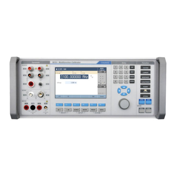
- Page 8 Display is divided into several sections with following meaning: 1. Selected function. Symbol on the left indicates system status ( standby, settling in, ► running). There may be additional Warning symbols on the right: Warm-up in progress. Calibrator is fully operational but it may be outside specifications.
- Page 9 There are 3 button groups in total on the front panel. Softkeys and menu buttons under the display, function buttons on the right and numeric entry buttons with rotary knob and cursor buttons in between. 1. SELECT. Selects previous/next parameter on display. Selected parameter can be edited and relevant tooltip is shown (if enabled).
- Page 10 5. RS-232 connector 6. External signal synchronization input 7. External signal synchronization output 8. MSI connectors (2x) for control or synchronization with other Meatest devices 9. Fan outlet cover Every 9010+ Multifunction Calibrator delivery includes following items: - USB stick with user manual...
- Page 11 When controlled remotely, maximum ratings of calibrator’s output signals as well as all other specifications are the same as in manual mode. Meatest software package WinQbase + Caliber is recommended for best automation results. This system is designed for automated and semi automated calibrations of digital and analogue meters including uncertainty calculation, result evaluation and certificate printing according to ISO 17025 standard.
- Page 12 See 9010 SCPI manual for complete SCPI reference, more details on communication setup and troubleshooting.
- Page 13 Inspect package contents when unboxing the calibrator for the first time. See chapter 1.3 for complete list of accessories. Place the instrument on a level surface before powering on and let it stabilize for at least one hour if the instrument has been stored outside of reference temperatures beforehand.
- Page 14 The calibrator must be powered by 230/115 V – 50/60 Hz mains. Before connecting the instrument to the mains, check the position of the mains voltage selector located on the rear panel. Set appropriate voltage selector position either 115 V or 230 V. Plug one end of the power cord into connector on the rear panel and connect the other end of the power cord into a wall outlet.
- Page 15 Calibrator output (source) function can be set using FUNCTION buttons. Push any FUNCTION button to change function or push the button repeatedly to scroll through function modes if available (for example DC and AC in voltage function). Once a function is selected, you can change the main value as well as auxiliary output parameters like frequency in AC modes or phase shift in AC power function.
- Page 16 If an obvious failure occurs during the operation (e.g. the display is not lit, the fan is not turning), the calibrator must be switched off immediately. First, check the fuse located in the power cord receptacle. Procedure is following: - Remove the end of power cord from the mains connector at the rear panel. - Insert the blade of a flat screwdriver into the opening cut in the mains voltage selector and pry out the fuse holder.
- Page 17 Four buttons on the front panel give access to main menu sections: - Source. Shortcut to section of Menu > Device related to currently selected source function. - Meter. Shortcut to Menu > Device > Meter - Preset. Save or recall predefined calibrator configurations. See chapter 3.6 for more details. - Menu.
- Page 18 Sections of currently used functions can be accessed directly using SOURCE and METER shortcut buttons on front panel. Picture below shows DC power section as an example of device menu. System menu contains general, user-accessible device settings: - Language Language version of user interface [0 –...
- Page 19 Calibration menu contains internal calibration constants and other tools for device adjustment and is therefore password protected. See chapter 6 for more details on 9010+ adjustment. Calibration menu has following items: 1. Data. Contains current calibration data. Structure of this menu is described in chapter 6.1. 2.
- Page 20 1. Connect the voltmeter to the calibrator as shown on the figure below. 2. Select appropriate function and range on the voltmeter 3. Push VOLTAGE function key on the calibrator. DC mode is automatically set. Push VOLTAGE key once more if AC voltage is requested. 9010 Multifunction Calibrator Terminals Entry...
- Page 21 Calibrator has unique feature of creation by customer defined output AC signal. Definition on the signal is based on setting of amplitude and phase shift of harmonic products related to basic, fundamental frequency. Number of harmonic products is limited to 50 but maximum frequency of harmonic product cannot exceed 5 kHz.
- Page 22 Harmonic preset feature works similarly as normal preset feature. Harmonic preset allows you to save and recall one of up to 22 configurations. First preset is 00 Sine and it can’t be changed or saved. If the preset is being edited and not saved, an * appears in front of the name on the main panel. Harmonic preset is selected either from the main screen of the VAC, IAC, PAC functions from "Harmonic"...
- Page 23 Voltage function SETUP can be activated using SETUP SOURCE key. Following screen will appear: SETUP offers additional voltage function settings. Use keys and EDIT soft key to change following items:...
- Page 24 1. Connect the ammeter to the calibrator as shown on the figure below. 2. Select appropriate function and range on the ammeter (multimeter) 3. Push CURRENT function key on the calibrator. DC mode is automatically set. Push CURRENT key once more if AC current is requested. 9010 Multifunction Calibrator Terminals Entry...
- Page 25 Current function SETUP can be activated using SETUP SOURCE key. Following screen will appear: SETUP offers additional current function settings. Use keys and EDIT key to change the following:...
- Page 26 Basic version of the calibrator offers continuously adjustable resistance decade LVR, based on resistance simulation using electronic circuits. The function is designed for calibration of standard resistance function of various multimeters which use low level signals. The mode is signed VARIABLE. FIXED mode offers set of fixed decadic resistors with higher accuracy.
- Page 27 9010 Multifunction Calibrator Terminals Entry Function SOURCE 1100V 1V PK 1500V 20V PK SCOPE 10V PK 1 00V PK 2V PK OPER STBY METER METER FUNC NULL 25V PK 10V PK 50V PK MAX 50 V PK MAX SELECT SETUP SYSTEM Fixed mode offers high accuracy of sourced resistance however range of resistance is limited to fix decadic values.
- Page 28 High resistance decade offers fully programmable series connected resistance with maximum working voltage 1500 V. The decade is applicable on DC voltage. Do not use AC test signal. High resistance decade is available only in two-wire configuration. Push MODE soft key to display list of modes. Select High resistance item and confirm with ENTER. 1.
- Page 29 Low resistance mode is available in two- terminal connection only with maximum test from 2 to 5 V depending on set value. See specification for test voltage and test current limitations. Push MODE soft key to display list of modes. Select Variable and confirm with ENTER. 1.
- Page 30 Only output voltage and current can be set in DC mode. In AC mode frequency of the output signal and phase shift between voltage and current can set as well. 1. Connect power meter to the calibrator as shown on the figure below. 2.
- Page 31 In Harmonic mode any distortion represented with amplitude and phase shift can be set in output signal. Harmonic content of output voltage can be set independently. Select Power mode using POWER key. Push Harmonic soft key. Following screen will appear: See chapter 4.1.3 for individual harmonic component editing, previewing, saving, and loading.
- Page 32 Except main power value parameter, softkeys below the display can directly edit auxiliary parameters: Harmonic softkey enables setting of non-sinusoidal waveform with harmonic distortion. Move active line to position Harmonic using SELECT keys. Soft keys meaning is changed enabling setting of higher harmonic content.
- Page 33 Following items can be modified:...
- Page 34 The function enables to source output voltage from current terminals. Two synchronous voltage outputs are practically available in this mode. Simple resistance converter is used for transformation inside the calibrator. Range of output voltage is 5 mV to 5 V, AC or DC. Using setting of equivalent coefficient appropriate range of simulated current can be set.
- Page 35 - Negative square Negative square wave signal with adjustable duty cycle ratio and frequency - Symmetric square Symmetric square wave signal with adjustable duty cycle ratio and frequency Voltage mode has two submodes Low and High. In Low mode output signal is connected to the front panel coaxial connector.
- Page 36 Push the OPER key to connect signal to the output terminals (N connector). Oscilloscope input impedance can be measured by scope option itself. Press R-meter softkey in any scope option function mode to activate impedance measurement function: Impedance is measured at HF terminal (N connector). 50Ω oscilloscope inputs shall be measured in 100Ω...
- Page 37 Scope option has two impedance configurations of HF coaxial output connector, 50 Ω and Low Z output impedance. Requested setting can be selected in Scope SETUP, item Impedance. In Low Z mode output impedance is close to zero Ω, typ. < 1Ω, in 50 Ω mode is output impedance set to 50 Ω ± 2 %. Setting of output impedance is indicated in the field SOURCE on the display using labels „LOW Z“...
- Page 38 - Terminal ground, enables internally LO output terminal grounding Coefficients of „PT User“ scale. RTD calculation formula is = R0 * (1 + T*(A + T*(B + T*C(T-100.0)))) , where T is temperature in °C and R0 is nominal resistance of temperature sensor at 0 °C. In TEMPERATURE TC function calibrator simulates thermocouple temperature sensor by sourcing such DC voltage to the output terminals which corresponds set temperature and selected type of sensor.
- Page 39 TEMPERATURE TC function has related SETUP function. The SETUP can be opened by pushing the key SOURCE SETUP. It contains following items: - Temperature unit selection, °C, °F or K - Terminal ground, enables internally LO output terminal grounding - Output mode either passive (more accurate) or active (higher current available) The calibrator is equipped with built-in process multimeter.
- Page 40 To measure external signal: 1. Connect source of signal to the input terminals: o Use A and COM terminals for current measurement. o Use 9000-60 adapter connected to R terminal to measure resistance and RTD temperature sensors. o Use V and COM terminals for all other meter functions. When measuring thermocouples with auto cold junction compensation, connect Adapter 91 as follows: 2.
- Page 41 Multimeter function has direct access to several subfunctions. Push SELECT key until active window Meter is selected. Meaning of soft keys beneath the display is changed. Soft keys enables fast access to following functions: - Smoothing Smoothing filter activation - Scaling Allow to scale measurements relative to a reference value - Statistics Statistical data can be displayed...
- Page 42 Reading of the multimeter are statistically evaluated when STATISTICS function is switch on. Use Statistics soft key to display statistic parameters. Symbol MATH is displayed in METER information field. Following data are displayed: - Min Minimum reading - Max Maximum reading - Span Max-Min difference - Average...
- Page 43 The multimeter has related SETUP menu offering selection of parameters shown in table below. Push METER SETUP key to display SETUP screen. Direct access to the mathematic parameters is also using soft keys beneath display: Smoothing, Scaling, Statistics and Limits. The mathematic functions which have been switch on have indication with yellow bar in soft key description in the bottom line.
- Page 44 9010+ supports connection of external options through two MSI bus connectors. Multiple devices can be daisy chained in one connector. Press OPTION for Function menu and then press OPTIONS soft key to search for external options. List of all externally connected options that are supported will show up: Status –...
- Page 45 If you don’t have the necessary equipment or can’t do the calibration on your own, please ask local Meatest representative to help you calibrate this device. Following instruments are required for performance verification test: - 8½...
- Page 52 Adjustment is done through MENU > Calibration > Data. This menu item is password protected, default factory set calibration code is “9010”. Calibration data are sorted in a tree structure with following hierarchy: 1. Function groups (source and measurement) 2. Functions (f.e. Voltage DC) 3.
- Page 53 Once range level of the tree structure is reached, calibration points are displayed in following format: Upper part shows selected function and range on the left, selected calibration point on the left and remote control command used to access this specific point in tooltip bar on top. Lower part of the display shows: - Nominal value - Requested accuracy of used calibration standard - Last calibration date of this point...
- Page 54 In both cases the procedure starts by connecting required standard to relevant terminals as shown on the right side of display. Meter functions measure all the time, source functions have to be switched on first using OPER key. Then adjust the main value accordingly and confirm with SAVE softkey. HISTORY softkey allows you to check all previous values of this specific calibration point, PREVIOUS and NEXT softkeys navigate through other calibration points in selected range.
- Page 56 0 Ω, 0.1 Ω, 1 Ω, 10 Ω, 100 Ω, 1 kΩ, 10 kΩ, 100 kΩ, Fixed resistance nominals: 1 MΩ, 10 MΩ, 100 MΩ, 1 GΩ 1 nF, 10 nF, 100 nF, 1 µF, 10 µF, 100 µF Fixed capacitance nominals:...
- Page 59 (.upl) for your device. If your device is not listed, contact Meatest support and ask for firmware update file for your device. 2. Check if the update file version is greater than yours, installed FW version can be found in MENU >...
- Page 60 The following table lists an overview of error codes that you might come across when operating the calibrator manually. Complete list of errors is available in SCPI manual.
- Page 61 All absolute uncertainty specifications in this document are defined at a confidence interval of 95%, extension coefficient k = 2. Uncertainties include 12 months long-term stability, temperature coefficient, linearity, load and line regulation and the traceability of factory and National calibration standards. Recommended recalibration interval is 1 year.
- Page 62 0.00000 mV – 1050.000 V DCV range summary: – 1050.000 V ACV range summary: 1.00000 mV Voltage ranges: auto, 20 mV, 200 mV, 2 V, 20 V, 100 V, 280 V, 1050 V 150 – 1050 V for 1050V range, 5 – 100 % of range otherwise Range limits: Available AC units: RMS, peak, peak-peak, average...
- Page 63 Waveforms: symmetrical square, ramp up, ramp down, triangle, truncated sinus with THD 13.45 %, harmonics – 200.0000 V Voltage range: 1.00000 mV (282 V max.) 15.000 – 1000.00 Hz Frequency range: 0.21 % of range + 70 µV Peak value uncertainty:...
- Page 64 0.0000 A – 30.00000 A DCI range summary: 10.0000 A – 30.00000 A ACI range summary: auto, 200 µA, 2 mA, 20 mA, 200 mA, 2 A, 20.5 A, 30 A Current ranges: 5 – 100 % of range Range limits: Available AC units: RMS, peak, peak-peak, average 15.000 Hz –...
- Page 65 Waveforms: symmetrical square, ramp up, ramp down, triangle, truncated sinus with THD 13.45 %, harmonics 100.0000 µA – 2.000000 A Current range: (2.82 A max.) 15.000 – 1000.00 Hz Frequency range: Peak value uncertainty: 0.21 % of range + 700 nA 0.00000 mV –...
- Page 66 Measurement modes: 4W, 2W 0.0000 Ω – 1.000000 MΩ in 4W mode Resistance range summary: 0.0000 Ω – 1.100000 GΩ in 2W mode 0.0 – 1000.0 mΩ 2W compensation:...
- Page 67 0.0000 Ω – 100.0000 kΩ in 4W mode Resistance range summary: 0.0000 Ω – 1.000000 GΩ in 2W mode 100.00 kΩ – 10.000 GΩ continuous, 100 GΩ fixed standard Resistance range summary: 0.0 – 1500.0 V Test voltage measurement:...
- Page 68 Measurement modes: 0.800000 nF – 120.0000 mF Range summary: Maximum load: or 150 mA , whichever comes first 1.000000 nF – 100.0000 µF Range summary: Maximum load: 25 V or 150 mA , whichever comes first ± 10 % Tolerance from nominal:...
- Page 69 0.200000 V – 1050.0000 V Voltage range summary: 0.200000 mA – 30.00000 A Current range summary: 0.04000 mW – 30.0000 kW Electric power range: DC, 15.000 Hz – 1000.00 Hz Frequency range: 2.000 s – 3600.000 s Energy period range: 0.00°...
- Page 70 This example is based on following parameters: - Function: AC active power - Set value: 500 W (100 V, 10 A, 60° phase shift), 50 Hz Individual items in formula are then calculated like this: - dU = 0.025 % + 0.010 % of range = 0.045 % of 100 V value - dI = 0.05 % + 0.01 % of range = 0.06 % of 10 A value - dPF = [1 –...
- Page 71 Harmonic products may be added in all AC functions of the calibrator (voltage, current, power, energy). Max. peak amplitude of single √ 2 × full range fundamental harmonic: Amplitude uncertainty: 0.2 % of fundamental harmonic range Max. frequency: 1 kHz Min.
- Page 72 Sensor types: RTDs, thermocouples -200.00 °C – 800.00 °C Temperature range summary: Temperature scales: Pt 3850 IPTS68, Pt 3851 ITS90, Pt 3916, Pt 3926, Ni 120, custom 20 – 2000 Ω Range of R0 setting:...
- Page 73 -250.00 – 2315.00 °C (by sensor type) Temperature range summary: Thermocouple types: B, C, D, E, G2, J, K, M, N, R, S, T Cold junction comp. modes: off, manual, automatic Sensor type: Pt100 0.1 °C with calibration constants saved in 9010+, Temperature uncertainty: 0.3 °C otherwise <...
- Page 74 Waveform: positive square wave / 50 Ω Amplitude: > 1 V Division ratio: off, 1, 10, 100 Rise time: < 1 ns Output terminal: coaxial N connector Waveforms: DC (positive, negative), square wave (symmetrical, positive, negative) 0.100000 Hz – 100.0000 kHz Frequency range: Frequency uncertainty: 25 ppm...
- Page 75 Output terminal: coaxial N connector Waveform: sinusoidal 15.00000 Hz – 400.00 MHz Frequency range: Frequency uncertainty: 2.5 ppm – 1.5000 V Amplitude range: 1.400 mV Output terminal: coaxial N connector Waveform: positive square wave 0.100000 Hz – 400.000 MHz Frequency range: Frequency uncertainty: 2.5 ppm 2.5 ns –...
- Page 76 Output terminal: coaxial N connector Waveform: sinusoidal 15.00000 Hz – 1 100.00 MHz Frequency range: Frequency uncertainty: 0.1 ppm – 1.5000 V Amplitude range: 1.400 mV (above 1 GHz 1.0000 V Output terminal: coaxial N connector 0.1 Hz – 400 MHz positive square wave Waveform: 400 MHz –...
- Page 77 Input terminal: coaxial N connector 100 Ω, 2 MΩ Ranges: in 10 % – 100 % of range Measurement uncertainty: 0.1 % of value Functions: DCV, DCI, frequency, resistance, TC, RTD Terminal ratings: 25 V between V and COM 10 V between A and COM 50 V between COM and PE...
- Page 78 -250.00 – 1820.00 °C Temperature range: Cold junction comp. modes: Manual...
- Page 79 According to EN ISO/IEC 17050-1:2010 standard as well as 2014/30/EU and 2014/35/EU directives of European Parliament and European Council, MEATEST, spol. s r. o., manufacturer of 9010+ Multifunction Calibrator, based in Železná 3, 619 00 Brno, Czech Republic, declares that its product conforms to following specifications: - EN 61010-1 ed.
Need help?
Do you have a question about the 9010+ and is the answer not in the manual?
Questions and answers